
Evd drain in head of a cranisotosis patient how to keep below head level
EVD external ventricular drain positioning below head level craniosynostosis ICP management
https://pmc.ncbi.nlm.nih.gov/articles/PMC4450504
EVD Drain Positioning: Keeping the Collection Chamber Below Head Level
Why "Below Head Level" Matters
Step-by-Step Setup
1. Identify the Zero Reference Point
- The Foramen of Monro is the anatomical zero reference.
- Externally, this corresponds to the external auditory meatus (tragus/ear canal opening) when the patient is supine.
- In the lateral decubitus position, the reference shifts to the mid-sagittal line (midpoint between the eyebrows).
2. Zero (Level) the Transducer
- The pressure transducer on the EVD system must be aligned exactly at the level of the tragus.
- Use a carpenter's level or a laser leveling device - visual estimation alone is inaccurate and should not be relied upon.
3. Set the Drip Chamber Height
- Once zeroed, the drip chamber (collection chamber) is positioned below the transducer/tragus by the prescribed number of centimeters.
- Standard settings are typically 10-15 cm H₂O below the foramen of Monro reference, but this is physician-prescribed and varies by:
- Target ICP
- Clinical condition (raised ICP vs. normal)
- Volume of drainage needed
At this set height: CSF drains whenever intraventricular pressure exceeds the height of the collection system. Flow stops when pressures equalize.
4. Practical Positioning Tips
- Mark the reference level on the IV pole or bedside stand so nurses can quickly re-check alignment.
- Re-level the system every time the patient's head position changes (turning, repositioning, raising/lowering HOB). Failure to re-level is a common nursing error.
- Clamp the drain during patient transport, transfer, or any significant movement to prevent sudden over- or under-drainage.
- Keep the drip chamber upright - horizontal positioning of an unemptied chamber can wet the filter and cause obstruction.
Special Considerations in Craniosynostosis
-
Distorted skull anatomy: Premature suture fusion alters the relationship between external landmarks and internal structures. The external auditory meatus is still the best available surface landmark for the Foramen of Monro, but be aware that skull shape abnormalities (e.g., turricephaly, scaphocephaly) can subtly shift relationships.
-
Pre-existing elevated ICP: Many craniosynostosis patients have chronically raised ICP. The target drainage height may be set more aggressively (lower) than usual. This must be confirmed with the neurosurgeon.
-
Small/compressed ventricles: In syndromic craniosynostosis, ventricles may be small. Tight ventricles increase the risk of catheter obstruction - if CSF stops flowing, briefly lowering the entire system confirms whether it is positional or a fixed obstruction.
-
Post-operative state: If the EVD is placed after cranial vault remodeling, head bandaging may obscure the tragus. Identify the reference point clearly before dressing is applied, and mark it externally.
-
Hydrocephalus: If craniosynostosis is complicated by hydrocephalus (10-15% of cases), drainage goals and target ICP are set by the neurosurgeon based on imaging and clinical status.
Summary Table
| Parameter | Standard Practice |
|---|---|
| Zero reference (supine) | External auditory meatus (tragus) |
| Zero reference (lateral) | Mid-sagittal line |
| Typical drainage height | 10-15 cm H₂O below zero reference |
| Leveling tool | Carpenter's/laser level (not visual) |
| When to re-level | Every position change |
| When to clamp | Transport, transfer, significant movement |
Key Rule
Give me a photo of evd in a child of craniostosis
external ventricular drain EVD child craniosynostosis hydrocephalus
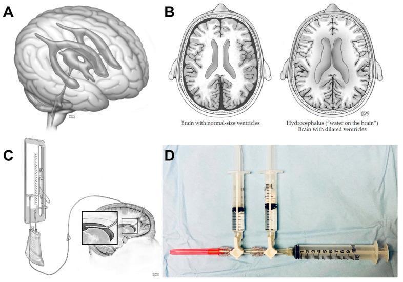
Educational medical composite illustrating hydrocephalus anatomy and external ventricular drain (EVD) management. (A) 3D anatomical diagram of the human brain showing the ventricular system, including lateral, third, and fourth ventricles. (B) Side-by-side axial illustrations comparing normal brain anatomy with hydrocephalus; the latter displays significant ventricular dilation and subsequent compression of surrounding brain parenchyma. (C) Medical illustration of an EVD Becker drainage system, showing the ventricular catheter's placement in the lateral ventricle and the external collection bag and pressure transducer setup. (D) Clinical photograph of a sterile isovolemic injection apparatus used for intraventricular drug administration (e.g., nicardipine). The setup includes a three-way stopcock connected to three syringes: a drug injection syringe, a sterile saline flush syringe, and a 10 mL cerebrospinal fluid (CSF) aspiration syringe. A red 18G needle is attached for port access. The composite demonstrates the clinical management of obstructive or communicating hydrocephalus, common in aneurysmal subarachnoid hemorrhage, emphasizing the 'volume out must equal volume in' isovolemic technique.
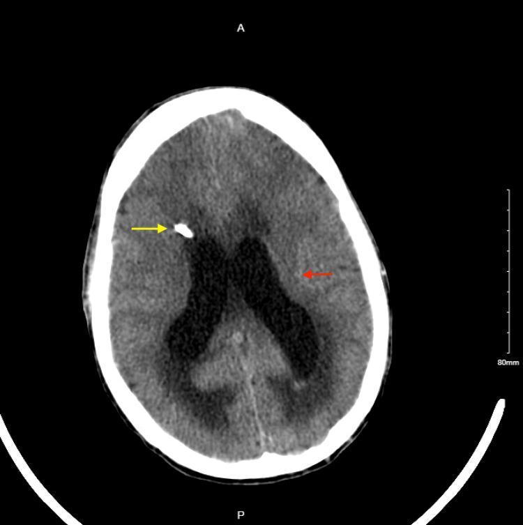
This axial non-contrast CT scan of the head demonstrates the placement of a right-sided external ventricular drain (EVD) in a patient with hydrocephalus. A high-density catheter is visible entering through the right frontal calvarium (yellow arrow), with its trajectory directed toward the ventricular system to facilitate cerebrospinal fluid (CSF) diversion. The lateral ventricles show interval decreased dilation compared to previous states, although they remain prominent. There is a notable reduction in periventricular hypodensity, representing decreased subependymal edema (red arrow) within the white matter surrounding the lateral ventricles. The brain parenchyma shows improved visualization of sulci compared to an acute obstructive state, indicating effective decompression of intracranial pressure. This diagnostic image is used to illustrate post-procedural management of increased intracranial pressure and the radiographic resolution of transependymal flow.
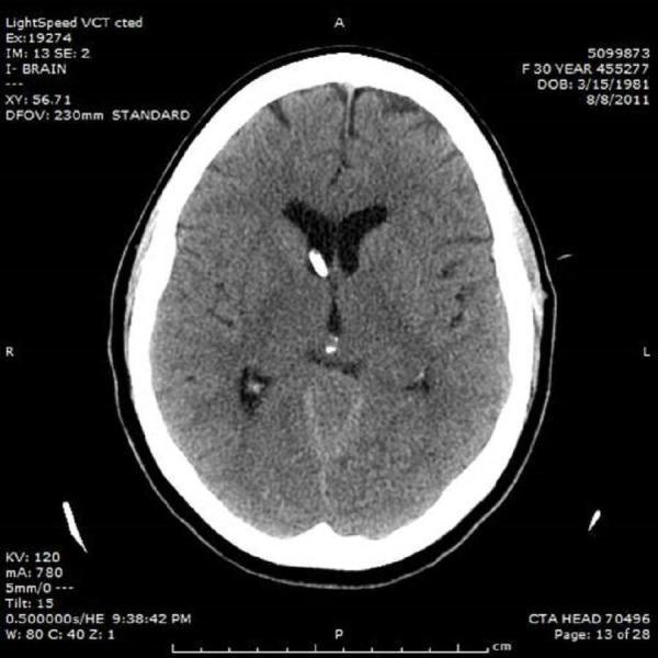
This diagnostic image is an axial non-contrast CT scan of the head demonstrating the placement of a right frontal external ventricular drain (EVD). The EVD is visible as a hyperdense, linear tubular structure traversing the right frontal lobe parenchyma, with its distal tip positioned within the frontal horn of the right lateral ventricle. The ventricular system, specifically the lateral ventricles, exhibits moderate enlargement consistent with acute obstructive hydrocephalus. There is a notable effacement of the cortical sulci, suggesting increased intracranial pressure. The brain parenchyma shows relatively preserved gray-white matter differentiation. This image serves as a clinical illustration of neurosurgical management for cerebrospinal fluid (CSF) diversion in the setting of acute hydrocephalus. Key educational features include the radiological appearance of neurosurgical hardware, ventricular morphology in obstructive disease, and the anatomical trajectory for Kocher's point cannulation.
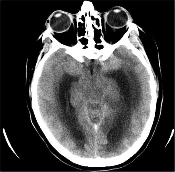
Axial non-contrast computed tomography (CT) scan of the brain at the level of the basal cisterns and midbrain. The image demonstrates a right-sided external ventricular drain (EVD) with its distal tip positioned within the right lateral ventricle. Significant clinical findings include diffuse cerebral edema characterized by global loss of gray-white matter differentiation and effacement of the cortical sulci. There is evidence of secondary hydrocephalus with enlargement of the temporal horns of the lateral ventricles. Signs of increased intracranial pressure are present, notably downward transtentorial herniation as indicated by the compression and effacement of the perimesencephalic cisterns. This imaging is characteristic of critical neurologic deterioration often associated with complications from cerebral venous thrombosis (CVT) or severe intracranial hypertension. The diagnostic focus is on evaluating the efficacy of EVD placement in relieving acute obstructive hydrocephalus and monitoring for signs of impending herniation syndromes.
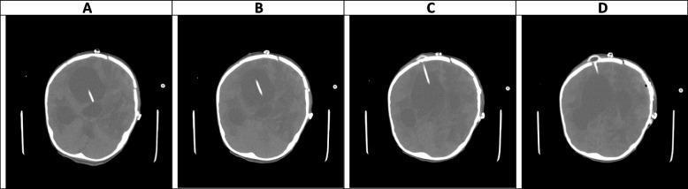
This composite diagnostic image consists of four non-contrast axial CT scans of the brain (labeled A-D), demonstrating significant neurosurgical and pathological findings on day 44 of clinical monitoring. The primary finding is severe, marked hydrocephalus characterized by massive dilatation of the lateral ventricles, including the temporal horns, as well as the third and fourth ventricles. This ventricular enlargement results in substantial compression of the surrounding brain parenchyma. An external ventricular drain (EVD) is visible as a linear, radiopaque structure traversing the right frontal lobe and terminating within the right lateral ventricle, most clearly seen in panels A and B. Multiple ill-defined hypodense areas within the white matter are suggestive of abscess formation or cerebritis. The imaging illustrates a 'communicating' or 'non-communicating extra-ventricular' type of hydrocephalus, likely persistent despite the EVD, suggesting potential drain malfunction or high severity of the underlying condition. The scan also shows evidence of previous craniotomy with associated calvarial defects.
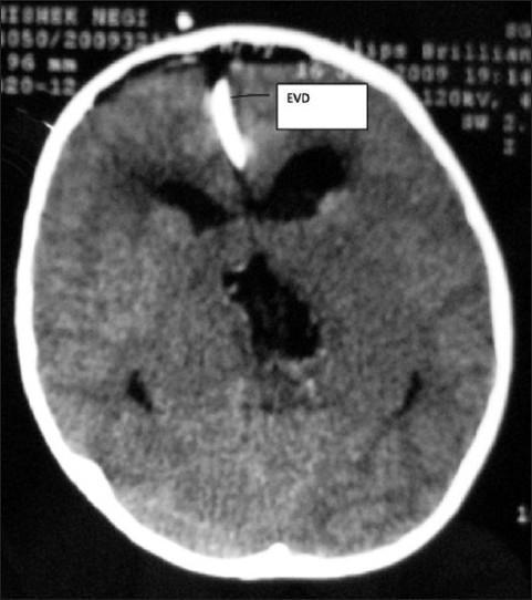
This diagnostic image is an axial noncontrast CT scan of the head, capturing a postoperative view (Day 1) following neurosurgical intervention. The scan highlights an external ventricular drain (EVD) in situ, appearing as a linear, high-density (hyperdense) structure originating from the right frontal scalp, traversing the parenchyma, and terminating in the anterior aspect of the right lateral ventricle. The lateral ventricles show significant ventriculomegaly with distortion of their typical anatomy. Centrally, a large hypodense area is visible, representing the operative site cavity or residual tumor bed within the supratentorial compartment. The image demonstrates common radiological findings associated with the management of hydrocephalus or obstructive intracranial masses, specifically illustrating the hardware placement for cerebrospinal fluid diversion and the structural changes following surgical debulking. Clinical relevance includes assessing EVD positioning, monitoring for postoperative hemorrhage, and evaluating ventricular size changes in response to drainage.
EVD System Diagram (anatomy + drainage setup)
CT Scan: EVD In Situ with Hydrocephalus (right frontal approach)