
Give me an answer about safety features to prevent hypoxic mixture of gases in anaesthesia machine from standard anaesthesia equipment textbooks
Reading File
Now let me search the medical library for this topic using parallel queries.
Finding Sources
Finding Sources
Finding Sources
Finding Sources
Finding Sources
Finding Sources
Finding Sources
Finding Sources
Barash Clinical Anesthesia (9e) is in the library. Let me search it directly for the relevant sections.
Finding Sources
Block 9 has "Evaluation of the Circle System" which is relevant. Let me read the anesthesia machine block (block 9) more fully and also search for the specific safety features topic.
Reading File
This is the pre-use check section. I need to find the section specifically about safety features preventing hypoxic gas mixtures - things like oxygen ratio controllers, fail-safe valves, etc. Let me search further back in the Barash block 9 (it covers pages 2055-2341, which is the anesthesia machine chapter).
Reading File
The block 9 content I've read so far is mostly references and checkout procedures. The key safety feature content is likely in a different part of the chapter. The block covers pages 2055-2341, which is a large section. Given the references mention "hypoxia", "oxygen proportioning device", and "fail-safe", let me look for the main content earlier in the chapter by reading from a different offset. Let me also look at what block the anesthesia machine chapter starts in.
Finding Sources
Block 8 has all the key sections. Let me read them in parallel.
Reading File
Reading File
Excellent! Now let me read the proportioning systems section and the oxygen analyzer section.
Reading File
Reading File
I now have enough key content. Let me also read the Drager ORMC (Oxygen Ratio Monitor Controller) section which should be right after the Link-25 section.
Reading File
Reading File
I now have comprehensive content from Barash's Clinical Anesthesia. Let me also fetch the key diagram image showing the flowmeter sequence.
Loading Image
Loading Image
I now have all the information needed to write a comprehensive, textbook-based answer. Let me compile everything.
Safety Features to Prevent Hypoxic Gas Mixture in the Anaesthesia Machine
Source: Barash, Cullen, and Stoelting's Clinical Anesthesia, 9th Edition (pp. 1944-1966)
Contemporary anesthesia machines have a cascade of safety devices that work together to minimize the risk of delivering a hypoxic gas mixture. These are arranged from upstream (high-pressure system) to downstream (common gas outlet).
1. Pneumatic and Electronic Alarm Devices
Older anesthesia machines use a pneumatic alarm device that provides an audible warning when oxygen supply pressure drops to a predetermined threshold (e.g., 30 psig). Contemporary workstations use pressure transducers and electronic alarms to alert the clinician before downstream safety mechanisms are triggered.
2. Oxygen Failure Cutoff ("Fail-Safe") Valve
This valve is present in the gas line supplying each flowmeter except oxygen. It is controlled by oxygen supply pressure and shuts off (or proportionally decreases) the supply of all other gases (N2O, air) as oxygen supply pressure falls.
Important caveat: The term "fail-safe" is a misnomer. This valve does not prevent a hypoxic mixture by itself - it only acts when oxygen supply pressure falls. If oxygen is flowing at a low concentration but adequate pressure, the fail-safe valve remains open and a hypoxic mixture can still be delivered.
- GE machines use a pressure-sensor shutoff valve (threshold ~20 psig): when O2 pressure exceeds 20 psig, the valve opens and N2O flows freely; when O2 drops below 20 psig, the spring closes the valve and N2O stops.
- Second-stage oxygen pressure regulator (on some GE workstations): set at 12-19 psig to provide a constant output oxygen flow when supply pressure exceeds this threshold. The fail-safe valve is set at a higher threshold (20-30 psig) to ensure oxygen is the last gas flowing if pressure fails.
3. Flowmeter Sequence (Oxygen in the Downstream Position)
Flowmeter leaks are a significant hazard because flowmeters are located downstream from all machine safety devices except the oxygen analyzer.
Eger et al. (1963) demonstrated that if a flowmeter leak exists, a hypoxic mixture is less likely to occur if the oxygen flowmeter is located downstream (closest to the common gas outlet) from all other flowmeters.
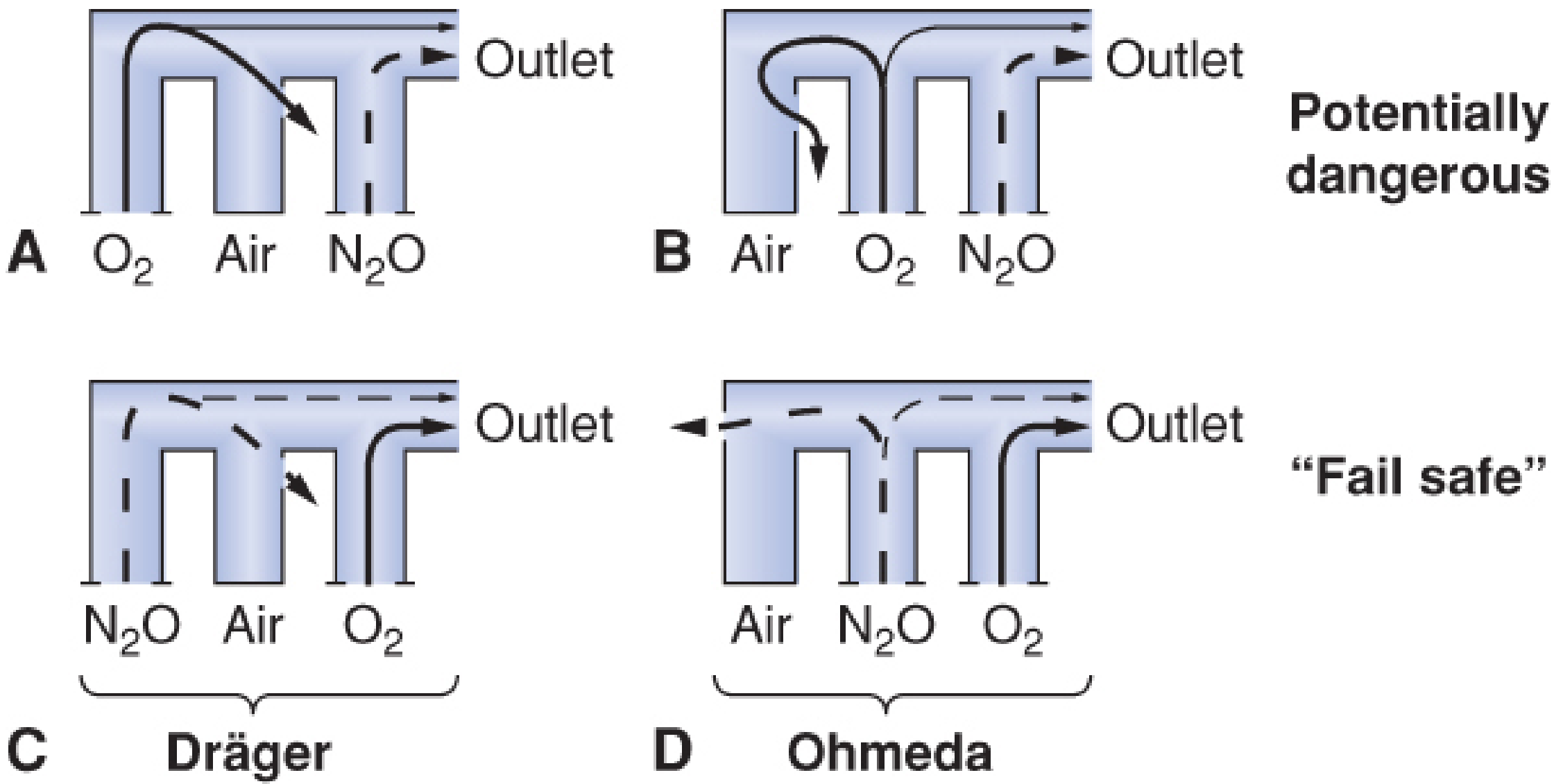
Figure 25-14 (Barash, p. 1955): When N2O is downstream and a leak exists (A, B), a hypoxic mixture results - O2 escapes through the leak while all N2O goes to the outlet. The "fail-safe" configuration places O2 downstream (C = Dräger arrangement; D = Ohmeda/GE arrangement).
Limitation: If the oxygen flow tube itself leaks, oxygen escapes and a hypoxic mixture can still result even with this arrangement, especially at high N2O:O2 ratios.
4. Proportioning Systems (N2O/O2 Interlock)
Manufacturers equip workstations with N2O/O2 proportioning systems designed to prevent hypoxic mixtures when nitrous oxide is administered. The minimum oxygen concentration at the common gas outlet is maintained at 23-25% depending on the manufacturer.
A. GE-Datex-Ohmeda Link-25 System
The Link-25 mechanically integrates the N2O and O2 flow control valves via a stainless steel chain linking sprockets on each valve:
- N2O valve: 14-tooth sprocket
- O2 valve: 29-tooth sprocket
- When the N2O valve is turned 2.09 revolutions, the O2 valve turns once

Figure 25-19A (Barash, p. 1962): The chain physically links the two sprockets. The gear ratio combined with differential supply pressures (N2O at 26 psig, O2 at 14 psig via second-stage regulator) ensures a maximum N2O:O2 ratio of 3:1 and a minimum 25% O2 concentration.
- The Link-25 actively increases oxygen flow when N2O is turned up, to maintain ≥25% O2.
- If the chain is broken, a 97% N2O concentration can result - a life-threatening failure.
B. Dräger Sensitive Oxygen Ratio Monitor Controller (S-ORC)
The S-ORC is a pneumatic interlock system used in Dräger workstations (Fabius, Apollo). It:
- Maintains a minimum fresh gas O2 concentration of 25 ± 3% when N2O is in use
- Requires a minimum oxygen flow of 200 mL/min whenever N2O is used
- Uses back-pressure from O2 and N2O flow resistors applied against rubber diaphragms on a mobile horizontal shaft to control a N2O slave control valve
- The O2 flow resistor value is 3-4 times that of the N2O resistor
Key contrast with Link-25:
- GE Link-25 increases O2 flow actively to maintain ≥25% O2
- Dräger S-ORC limits N2O flow passively to maintain ≥25% O2
- When O2 flow is <200 mL/min, the S-ORC slave valve closes completely, preventing any N2O flow
5. Oxygen Analyzer / Multigas Analyzer
The oxygen analyzer is positioned at the breathing circuit (inspiratory limb) and is the last and only safety device that can detect a hypoxic mixture resulting from:
- Downstream flowmeter leaks (bypassing all upstream proportioning devices)
- Administration of a third inert gas (helium, nitrogen, CO2) - these are not linked to the proportioning system
- Dilution of O2 by high concentrations of volatile agents (e.g., high desflurane, MAC ~7%, can dilute the O2 concentration below 21% when added downstream of the flowmeters)
A continuous, calibrated oxygen monitor with a low O2 alarm is therefore mandatory and represents the final safety net.
Limitations and Gaps in the Safety Cascade
| Hazard | Devices That Detect/Prevent It |
|---|---|
| O2 supply pressure failure | Fail-safe valve, pneumatic/electronic alarm |
| Flowmeter leak (non-O2 tube) | Downstream O2 flowmeter position |
| Flowmeter leak (O2 tube) | Oxygen analyzer only |
| Operator sets wrong N2O:O2 ratio | Proportioning system (Link-25 / S-ORC) |
| Third gas (He, N2, CO2) hypoxia | Oxygen analyzer only |
| High desflurane diluting O2 | Operator awareness + O2 analyzer |
| Broken chain (Link-25) | Defect check; O2 analyzer |
| Broken S-ORC diaphragm | O2 analyzer |
Summary of the Safety Cascade (Upstream to Downstream)
- Pipeline/cylinder supply - pin-index safety system prevents wrong gas connection
- Pneumatic/electronic O2 pressure alarm - warns of falling O2 pressure
- Fail-safe (pressure-sensor shutoff) valve - cuts N2O when O2 pressure falls
- Second-stage O2 pressure regulator - ensures constant O2 output pressure
- N2O/O2 proportioning system (Link-25 or S-ORC) - enforces minimum 25% O2
- Downstream O2 flowmeter position - reduces hypoxic risk from flowmeter leaks
- Oxygen flush valve - delivers 100% O2 at 35-75 L/min directly to circuit
- Continuous O2 analyzer - final sentinel; detects all remaining causes
"The oxygen monitor and/or integrated multigas analyzer are the only machine safety devices that can detect" a hypoxic mixture from a downstream flowmeter leak. Use of an oxygen analyzer to monitor inspired O2 concentration is mandatory if a third inert gas is used.
- Barash, Clinical Anesthesia, 9e, p. 1965-1966
This is a shared conversation. Sign in to Orris to start your own chat.