
Et tube parts image leveling
endotracheal tube parts diagram labeled anatomy
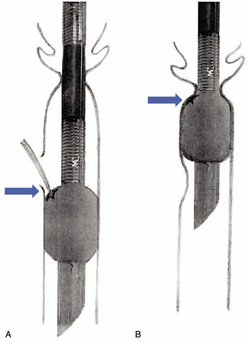
This medical illustration presents a comparison between two electromyogram (EMG) endotracheal tubes, labeled A and B, within a schematic representation of the trachea and vocal cords. The primary focus is the integrity of the inflatable cuff and its interaction with anatomical structures during extubation. Both tubes feature a spiral-reinforced main body with integrated electrodes for laryngeal nerve monitoring. Panel A illustrates a torn silicone cuff (indicated by a blue arrow and star) with a visible protrusion through the rupture. This diagram demonstrates a clinical complication where the vocal cords obstruct the tear site, preventing air from escaping and causing the cuff to remain spontaneously inflated despite deflation attempts. Panel B shows an intact, inflated cylindrical cuff positioned below the vocal cords for comparison. The illustration highlights the unique elastic properties of silicone EMG tube cuffs, which may retain their shape even when damaged, posing risks for traumatic extubation if the vocal cords catch on the irregular surface or prevent collapse. Key concepts include airway management, intraoperative neuromonitoring, and mechanical complications of reinforced endotracheal tubes.
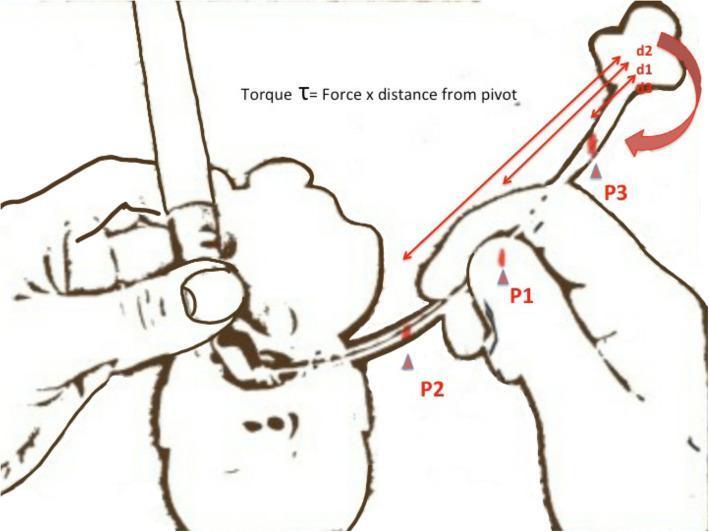
This medical illustration demonstrates the physics of torque during endotracheal intubation. The diagram shows a clinician's hands manipulating an endotracheal tube (ETT) through a patient's mouth using a laryngoscope. The focus is on the biomechanics of tube tip control. Three specific holding points on the ETT are labeled: P1 (proximal), P2 (middle), and P3 (distal, furthest from the tip). Annotations include the formula 'Torque τ = Force x distance from pivot'. Red arrows indicate the distance (d1, d2) from holding points to the distal tip. A large red curved arrow at the tip represents the ease of rotation. The educational purpose is to illustrate that as the holding point (pivot) moves further from the tip (e.g., at P3), the mechanical advantage increases, allowing for finer, more effortless adjustments of the tube tip movement toward the glottic opening. This concept is vital for anesthesiology and emergency medicine trainees to improve intubation success rates and maneuverability.
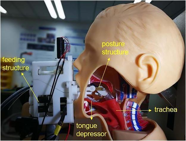
This clinical photograph/diagram shows a lateral cross-section of a medical manikin used to demonstrate a robotic-assisted intubation system. The image illustrates the mechanical interface between the 'Remote Robot-Assisted Intubation System' (RRAIS) and human upper airway anatomy. Key visible components include an external feeding structure situated at the mouth, which houses the mechanism for advancing the endotracheal tube. A robotic tongue depressor is shown inserted into the oral cavity, making contact with the base of the tongue to facilitate glottis exposure. Internally, a 'posture structure' is positioned within the oropharynx to control the tube's tip orientation. Anatomical landmarks labeled on the manikin's sagittal view include the tongue, oral cavity, and the trachea, demonstrating the intended pathway for the airway device. This visual serves as an educational tool for anesthesiology and emergency medicine, highlighting technological advancements in airway management and the mechanics of remote-controlled endotracheal intubation.
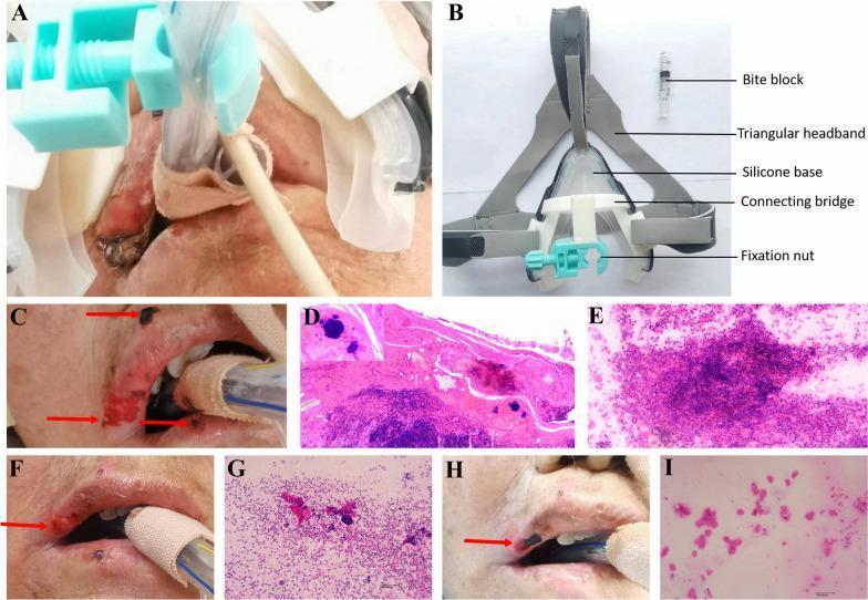
A composite medical figure illustrating a novel mask endotracheal tube (ETT) fixation device and its clinical impact on pressure injuries. (A) Clinical photograph of the device in situ on a patient, showing the integration of the mask-style base with the orotracheal tube. (B) Labeled structural diagram identifying the device components: a gray triangular headband, a clear silicone base, a white resin connecting bridge, a blue fixation nut for tube security, and a transparent bite block. (C, F, H) Serial clinical photographs showing the progression of lip pressure injuries. (C) Baseline shows severe erythema, ulceration, and crusting (indicated by red arrows). (F) Day 3 shows moderate resolution of the ruptured regions. (H) Day 5 demonstrates significant healing of the vermilion border and reduced lesion size. (D, E, G, I) Histopathological and cytopathological panels. (D) H&E stain of baseline tissue showing epidermal fractures and bacterial colonies (inset). (E, G, I) Tissue-print cytology progression from dense inflammatory exudate and necrosis (E) to significant reduction in inflammatory cells and debris by Day 5 (I).
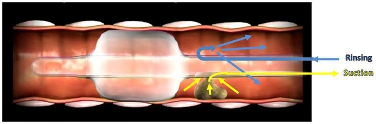
This medical illustration depicts a longitudinal cross-section of a human trachea containing an endotracheal tube (ETT) with an inflated cuff. The diagram focuses on the mechanism of Subglottic Secretion Drainage (SSD) enhanced by a rinsing system. The inflated ETT cuff is shown creating a seal against the tracheal wall to prevent microaspiration into the lower lungs. Just superior to the cuff, in the subglottic space, a mass of secretions is visible. The figure illustrates a dual-action clearance process: blue arrows labeled 'Rinsing' indicate the delivery of a saline solution into the subglottic space to dilute and mobilize the viscous secretions; yellow arrows labeled 'Suction' demonstrate the subsequent aspiration of these diluted secretions through a specialized dorsal suction lumen. This visual explains a clinical strategy used in intensive care to reduce the risk of Ventilator-Associated Pneumonia (VAP) by preventing the migration of pathogen-rich secretions past the ETT cuff.
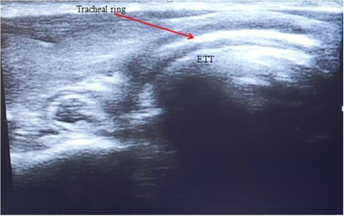
This diagnostic ultrasound image demonstrates a midline cross-sectional view of the adult trachea for the confirmation of endotracheal tube (ETT) placement. The image displays the anterior tracheal anatomy, characterized by a distinct, bright hyperechoic curved line representing the tracheal ring, indicated by a red arrow. Deep to this air-mucosal interface, a heterogeneous hypoechoic structure is visible within the tracheal lumen, labeled as 'ETT', representing the endotracheal tube in a correct intraluminal position. The visualization relies on the contrast in acoustic impedance between the echogenic tracheal wall and the relatively hypoechoic ETT. This ultrasound technique is used in emergency and anesthesiology contexts to verify airway management and rule out esophageal intubation, which would typically present as a 'double-track' or second air-mucosal interface lateral to the trachea. The image serves as an educational example of point-of-care ultrasound (POCUS) application in respiratory medicine and critical care.
A detailed labeled diagram of an endotracheal (ET) tube showing all parts: connector/adapter (15mm), tube body with cm markings, Murphy eye, inflated cuff (balloon), pilot balloon with one-way valve, inflation line, and beveled tip. Clean medical illustration with clear labels and arrows pointing to each component.
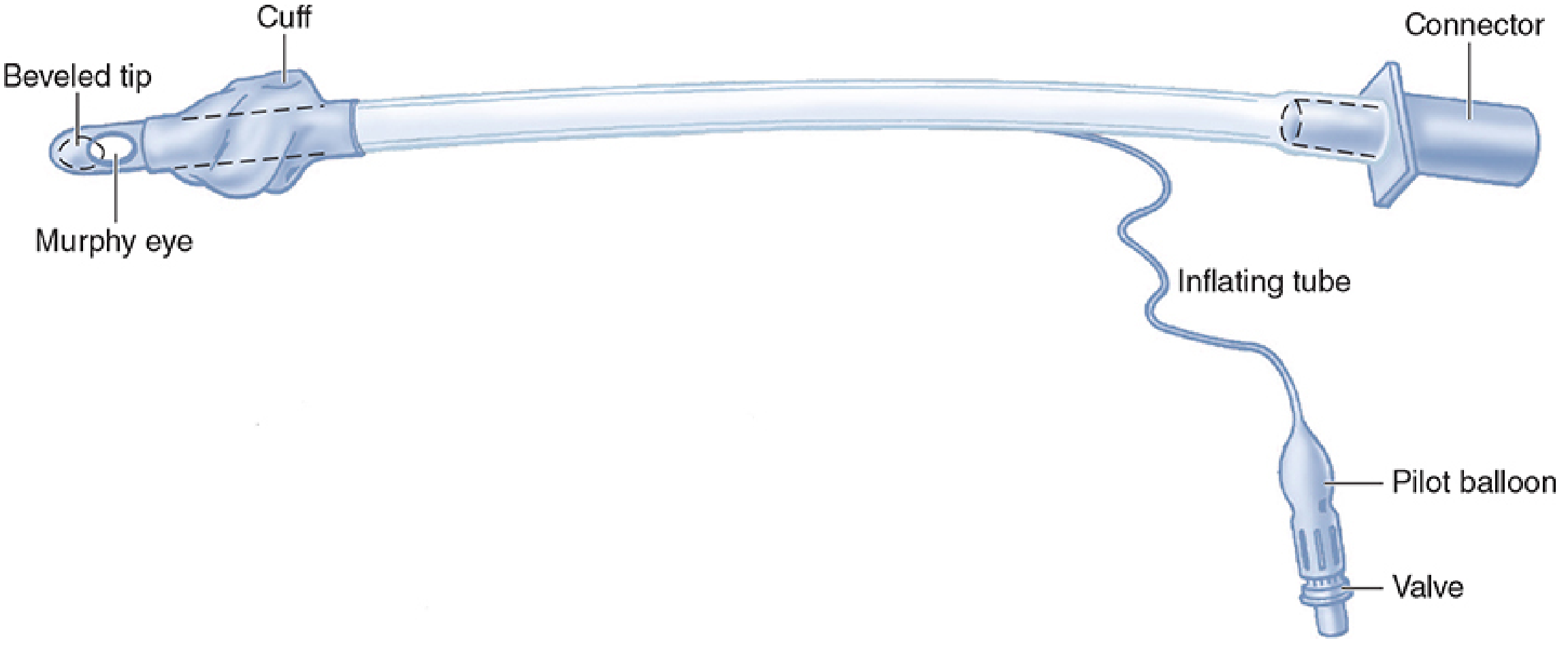
Parts of an Endotracheal (ET) Tube
| Part | Description |
|---|---|
| Connector (15 mm adapter) | Proximal end; connects to the breathing circuit or bag-valve mask. Standardized at 15 mm outer diameter. |
| Tube body | Made of polyvinyl chloride (PVC); has centimeter markings to confirm depth of insertion. |
| Cuff | Inflatable balloon near the distal tip; creates a tracheal seal for positive-pressure ventilation and reduces aspiration risk. Two types: high-volume low-pressure (HVLP) and low-volume high-pressure. |
| Inflating tube | Thin side channel incorporated into the tube wall; connects the cuff to the pilot balloon and valve. |
| Pilot balloon | Small external balloon; provides a gross visual/tactile indicator of cuff inflation status. |
| Valve (one-way) | Located at the end of the inflating tube; prevents air from escaping after cuff inflation. |
| Murphy eye | A small lateral hole just proximal to the beveled tip; prevents complete occlusion if the main opening abuts the carina or tracheal wall. |
| Beveled tip | Angled distal opening; aids visualization and passage through the vocal cords. |
ET Tube Sizing (for leveling/depth guidance)
| Age | Internal Diameter (mm) | Cut/Insertion Depth (cm) |
|---|---|---|
| Full-term infant | 3.5 | 12 cm |
| Child | 4 + age/4 | 12 + age/2 |
| Adult female | 7.0 - 7.5 | 21-23 cm at teeth |
| Adult male | 7.5 - 9.0 | 23-25 cm at teeth |
- Morgan and Mikhail's Clinical Anesthesiology, 7th Ed., pp. 588-589