

How do u approach this case , aboyt cervical fusion surgeries including anatomy Detailed from sweet and smidick and youmanns
cervical spine anterior cervical discectomy fusion ACDF anatomy surgical approach
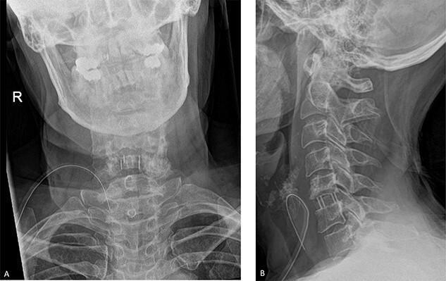
Post-operative cervical spine radiographs demonstrating an anterior cervical discectomy and fusion (ACDF) at the C5-C6 level. Panel A shows an anteroposterior (AP) view, while Panel B provides a lateral view. Visible surgical hardware includes a radiopaque interbody fusion cage positioned within the C5-C6 disc space to restore and maintain foraminal height. Small circular markers associated with the cage and longitudinal Caspar pins used for distraction are visible within the C5 and C6 vertebral bodies. The lateral view demonstrates preserved cervical lordosis and correct sagittal alignment of the C2-C7 vertebrae. Anterior soft tissue shadows are present, consistent with the surgical approach. This image is used to educate on spinal decompression techniques and the radiological appearance of cervical stabilization hardware in neurosurgery and orthopedics.
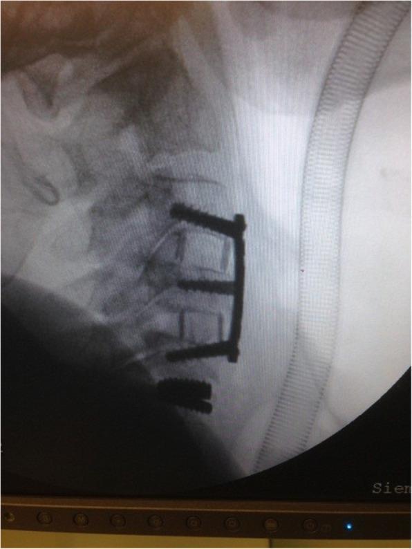
This lateral cervical spine radiograph demonstrates a complex hybrid surgical reconstruction involving multi-level stabilization. The image shows an Anterior Cervical Discectomy and Fusion (ACDF) construct spanning from C3 to C6. This consists of a radiopaque anterior cervical plate secured with three pairs of screws into the vertebral bodies. Within the intervertebral spaces at C3-C4 and C5-C6, interbody fusion cages are visible, designed to maintain disc height and promote osteosynthesis. Notably, at the C6-C7 level, a cervical disc prosthesis (artificial disc) is implanted, appearing as a distinct metal-on-metal or composite device designed to preserve motion at that segment. The alignment of the cervical vertebrae is maintained, and the hardware appears intact without evidence of migration or loosening. This case illustrates a 'hybrid' surgical approach, combining rigid fusion for spondylosis with motion-preserving arthroplasty to mitigate adjacent segment disease. An endotracheal tube or similar medical tubing is partially visible anterior to the neck, suggesting an intraoperative or immediate postoperative setting.
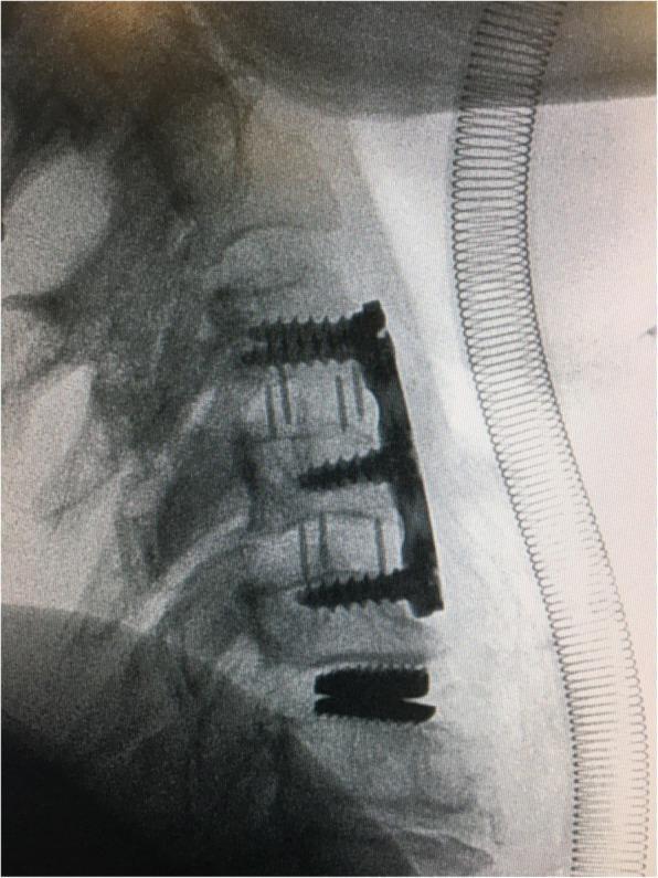
A lateral view plain radiograph of the cervical spine demonstrating a hybrid surgical construction for multilevel degenerative disc disease. The superior segment shows an anterior cervical discectomy and fusion (ACDF) construct at the C3–C4 and C4–C5 levels. This construct consists of a radiopaque anterior cervical plate anchored by five vertebral screws and interbody spacers with visible vertical markers to maintain disc height and promote arthrodesis. Immediately inferior at the C5–C6 level, a cervical disc prosthesis (artificial disc replacement) is visualized. The prosthesis consists of two radiopaque metallic endplates that articulate with the adjacent vertebral bodies, designed to preserve segmental motion while restoring disc space height. The image highlights a hybrid surgical approach that combines rigid stabilization through fusion at upper levels with motion-preserving arthroplasty at a lower level. An endotracheal tube with a visible coiled reinforcement is also present anterior to the spine.
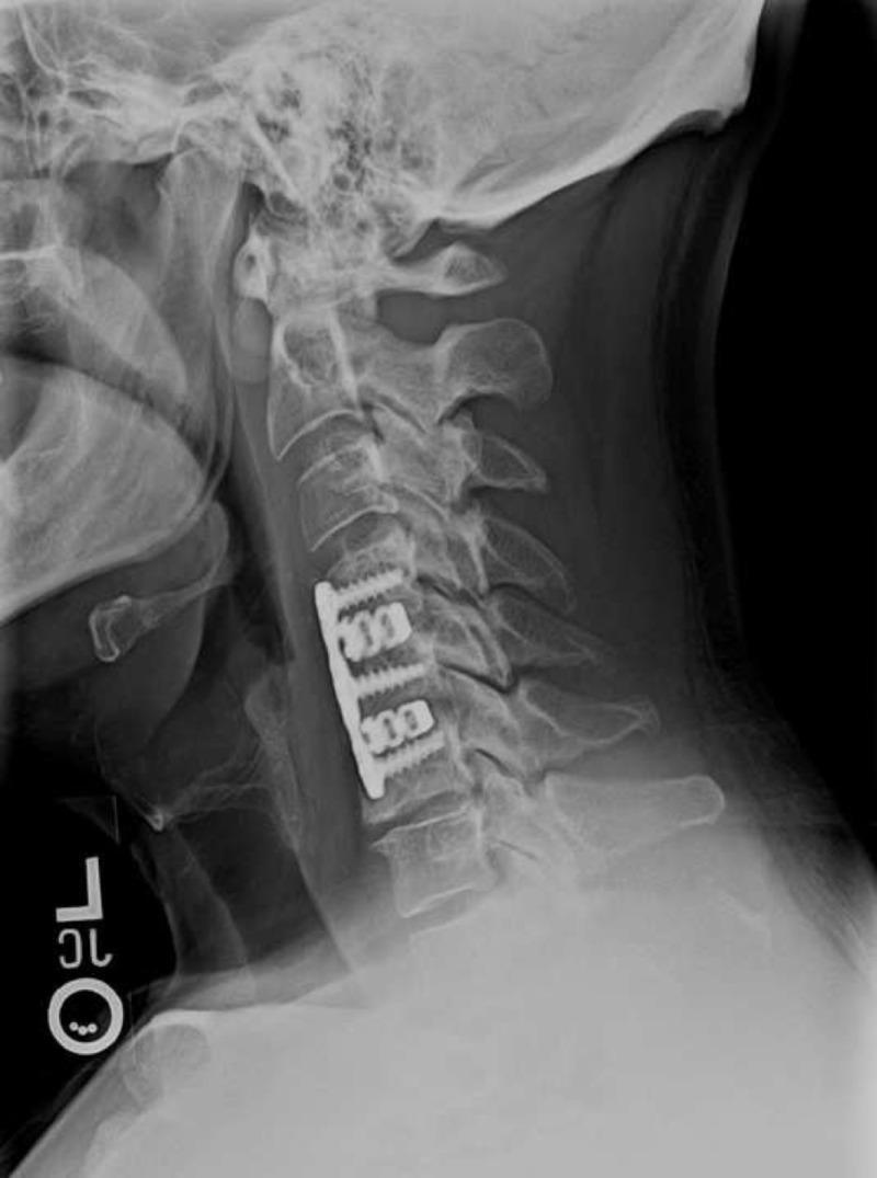
A diagnostic lateral X-ray of the cervical spine illustrating a post-surgical state at nine months follow-up. The image shows anterior cervical discectomy and fusion (ACDF) hardware in place, consisting of a rectangular metallic plate spanning the C4 to C6 vertebral bodies. The instrumentation is secured with four radiopaque screws, two inserted into the C4 vertebral body and two into the C6 vertebral body, providing stabilization across the C4-C5 and C5-C6 intervertebral spaces. The cervical spine demonstrates improved sagittal alignment with a preserved neutral to slightly lordotic curvature. The vertebral bodies exhibit sharp cortical margins and rectangular morphology, with visible resection of posterior osteophytes. There is evidence of early graft incorporation and stable intervertebral disc height within the fused segments. This imaging is clinically relevant for evaluating the success of spinal decompression and stabilization procedures in patients with radiculopathy or degenerative disc disease.
cervical spine anatomy cross section uncovertebral joint facet foramen transversarium
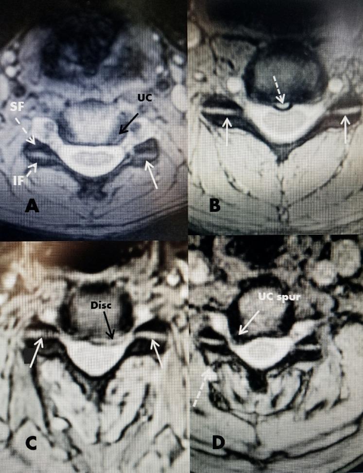
This set of four axial magnetic resonance imaging (MRI) scans demonstrates the normal anatomy and various degenerative pathologies of the cervical spine, with a focus on the facet and uncovertebral joints. Panel A displays normal anatomy, labeling the superior facet (SF), inferior facet (IF), and uncovertebral (UC) joint located lateral to the intervertebral disc. Panel B identifies a midline annular tear, visible as a small hyperintensity at the posterior disc margin. Panel C shows a disc herniation protruding into the ventral spinal canal. Panel D illustrates advanced degenerative changes, specifically a large osteophyte or 'UC spur' originating from the uncovertebral joint and projecting into the intervertebral foramen, alongside mild enlargement of the adjacent facet capsule. These images collectively serve as an educational resource for identifying key cervical structures and understanding how disc herniations, annular tears, and osteophytosis impact the spinal canal and neural foramina in relation to the stable horizontal orientation of the cervical facet joints.
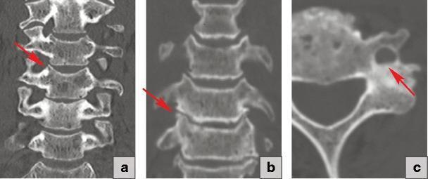
This composite diagnostic image consists of three panels demonstrating the progression of uncovertebral joint pathology in the cervical spine. (a) A coronal CT reconstruction showing a normal uncovertebral joint. The uncinate processes appear sharp and well-defined with a clear, uniform joint space (indicated by the red arrow). (b) A coronal CT reconstruction showing uncovertebral arthrosis. The red arrow highlights degenerative changes characterized by subchondral sclerosis and flattening of the uncinate process, resulting in joint space narrowing. (c) An axial CT scan showing hypertrophic uncovertebral arthrosis. The red arrow identifies significant bony overgrowth (osteophytosis) originating from the uncovertebral joint. This hypertrophic change causes encroachment and narrowing of the adjacent foramen transversarium, which clinically risks compression of the vertebral artery. These images serve as educational materials for neuroradiology and orthopedics, illustrating the spectrum from healthy anatomy to advanced degenerative joint disease and its secondary effects on adjacent vascular pathways.
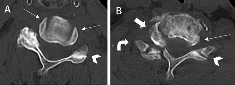
Diagnostic axial CT scan of the cervical spine comparing normal anatomy (Image A) with a unilateral cervical facet joint dislocation (UCFJD) (Image B). Image A demonstrates the normal concentric alignment of bilateral uncovertebral joints, where the uncinate processes frame the vertebral body symmetrically, creating the 'headphones sign'. Image B shows a traumatic right-sided dislocation in an 80-year-old male. Key radiological signs include the 'positive headphones sign,' where the vertebral body is shifted anteriorly and rotated towards the left, losing its symmetrical relationship with the right uncinate process (thick arrow). Furthermore, the left facet joint remains intact with a normal 'hamburger bun sign' appearance (chevron), while the right facet joint is disrupted and assumes a 'reverse hamburger bun sign' (curved arrow) due to the loss of joint apposition. This comparison illustrates critical diagnostic markers for identifying cervical spine instability and facet joint injuries on axial imaging.
posterior cervical laminoplasty laminectomy fusion technique multilevel stenosis myelopathy
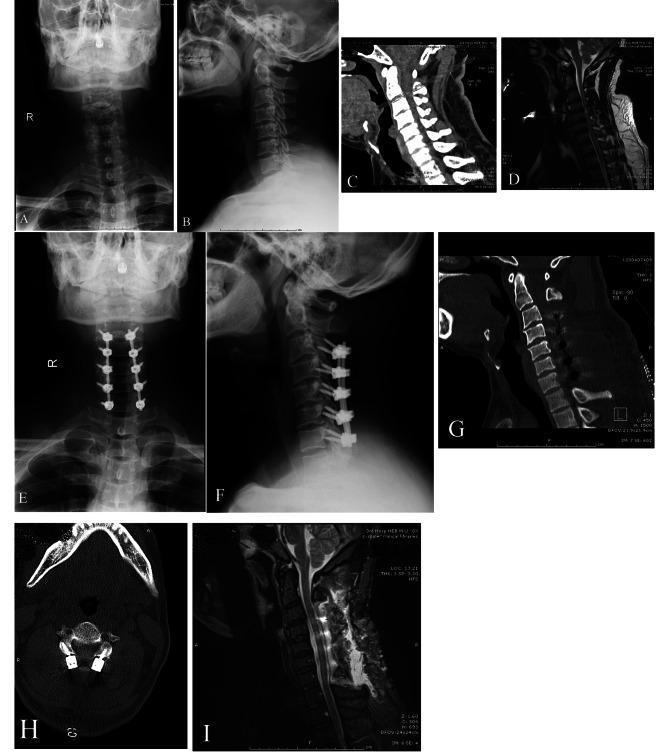
This composite of clinical images illustrates the preoperative and postoperative findings of a patient with multilevel cervical stenotic myelopathy (MCSM) treated via posterior cervical laminectomy and fusion (PCLF). The top row (A–D) displays preoperative state: (A, B) anterior-posterior and lateral X-rays showing cervical alignment; (C, D) sagittal CT and T2-weighted MRI highlighting cervical stenosis and spinal cord compression from C3 to C7 due to osteophytes. The middle and bottom rows (E–I) show postoperative results: (E, F) X-rays demonstrating bilateral lateral mass screw fixation and rods spanning C3–C7; (G) sagittal CT reconstruction and (H) axial CT slice confirming the laminectomy and the precise placement of screws within the lateral masses; and (I) sagittal T2-weighted MRI revealing successful decompression of the cervical spinal cord with increased subarachnoid space and resolution of stenosis. This educational material compares different imaging modalities (X-ray, CT, MRI) to evaluate surgical outcomes in spinal instrumentation and decompression.
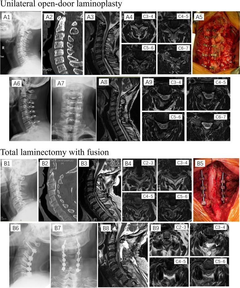
This composite educational image illustrates two surgical techniques for treating multi-segmental cervical canal stenosis: unilateral open-door laminoplasty (A1-A9) and total laminectomy with fusion (B1-B9). The visual content includes preoperative, intraoperative, and postoperative stages across multiple modalities. Preoperative X-rays (A1-2, B1-2), sagittal CT scans, and T2-weighted MRI (A3-4, B3-4) demonstrate multi-level spinal cord compression and ossification of the posterior longitudinal ligament (OPLL). Intraoperative clinical photographs (A5, B5) show the posterior approach: A5 depicts the hinged lamina stabilized with mini-plates and screws, while B5 shows total removal of the laminae with pedicle screw and rod instrumentation. Postoperative lateral and anteroposterior X-rays (A6-7, B6-7) verify hardware placement from C3 to C7. Postoperative MRI (A8-9, B8-9) highlights the decompression of the spinal cord and expansion of the vertebral canal. The comparison serves to distinguish between motion-preserving (laminoplasty) and stabilizing (laminectomy with fusion) procedures for cervical myelopathy.
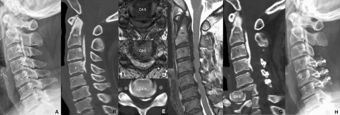
This composite figure presents a longitudinal clinical case of cervical myelopathy due to Ossification of the Posterior Longitudinal Ligament (OPLL). Panels A-F show preoperative status: Lateral X-ray (A) and sagittal CT (B) reveal extensive OPLL. Axial MRI (C, D) and CT (E) at the C4-C5 level demonstrate severe spinal canal stenosis and cord compression caused by a large, centrally-to-left located ossified mass. Sagittal T2-weighted MRI (F) confirms multilevel cord compression and high intramedullary signal intensity. Panels G and H show postoperative results: Sagittal CT (G) and lateral X-ray (H) at 4-year follow-up demonstrate surgical decompression via C4-C6 open-door laminoplasty and C3 laminectomy with C2 dome-like laminoplasty. Surgical hardware including titanium mini-plates and mini-screws are clearly visible, maintaining the expanded spinal canal while preserving cervical lordosis and sagittal alignment. The image illustrates the radiological diagnosis of OPLL and the structural outcomes of posterior decompressive surgery using laminoplasty spacers.
Case Approach: Cervical Fusion Surgery
(Based on Campbell's Operative Orthopaedics 15e, Youmans & Winn Neurological Surgery, Schmidek & Sweet Operative Neurosurgical Techniques)
IMAGING INTERPRETATION
| Level | Disc Height | Canal | Foramina |
|---|---|---|---|
| C4-C5 | Mild narrowing | Mild posterior spur | Mild NC arthropathy |
| C5-C6 | Severe loss | Significant posterior osteophyte complex - central stenosis | Foraminal stenosis bilateral |
| C6-C7 | Moderate-severe loss | Posterior ridging - central stenosis | Foraminal stenosis |
| C7-T1 | Relatively preserved | No significant stenosis | - |
- Multilevel degenerative cervical spondylosis (hard disc / disc-osteophyte complex)
- Neutral to mildly straightened cervical lordosis (no kyphosis >13°)
- No prior surgical hardware
- Extension views - this series was done to assess dynamic instability
STEP 1: SURGICAL ANATOMY
The Subaxial Cervical Spine (C3-C7)
- Each cervical vertebra has uncinate processes (of Luschka) bilaterally - unique to C3-C7
- The uncovertebral joints (joints of Luschka) lie lateral to the disc space; their hypertrophy causes both foraminal and canal stenosis - the core pathology here
- The vertebral artery ascends through the foramen transversarium from C6 upward; it sits ~1 cm lateral to the uncinate process and defines the lateral limit of safe anterior dissection
- Medial boundary: trachea and esophagus
- Lateral boundary: carotid sheath (CCA, IJV, vagus nerve)
- Deep: prevertebral fascia, longus colli muscle
- Recurrent laryngeal nerve (RLN): runs in the tracheoesophageal groove - more at risk on the right (non-recurrent variant in ~0.5%) - reason many surgeons prefer left-sided approach
- Superior laryngeal nerve: external branch vulnerable above C4
- The anterior longitudinal ligament (ALL) and posterior longitudinal ligament (PLL) - PLL resection is needed for central disc-osteophyte complex decompression
- C2 spinous process = large bifid process; C6 and C7 are prominent landmarks
- Lateral masses: rectangular bony columns posterior to the articular pillars; site of lateral mass screws in C3-C6
- C7 and T1: pedicle screws preferred here (lateral mass thin)
- Ligamentum flavum: between laminae - resected for decompression
- Dorsal nerve roots exit between superior and inferior facets in the foramen
STEP 2: CLASSIFICATION OF THE DISC DISEASE
- Unilateral soft disc protrusion - nerve root compression (lateral)
- Foraminal spur / "hard disc" - nerve root compression (lateral) ← this case at C5-C6, C6-C7
- Medial soft disc protrusion - spinal cord compression
- Transverse ridge / cervical spondylosis - spinal cord compression ← also present here
STEP 3: CLINICAL ASSESSMENT
Radiculopathy Signs (by level)
| Root | Pain | Weakness | Reflex Loss |
|---|---|---|---|
| C4 | Shoulder/neck | Levator scapulae | None |
| C5 | Lateral arm/shoulder | Deltoid, biceps | Biceps (diminished) |
| C6 | Lateral forearm, thumb/index | Biceps, wrist ext | Brachioradialis |
| C7 | Middle finger, dorsal forearm | Triceps, wrist flex | Triceps |
| C8 | Medial forearm, ring/small | Hand intrinsics | None prominent |
Myelopathy Signs (from cord compression)
- Hoffmann sign (flicking middle finger nail → thumb/index flexion)
- Lhermitte's sign (electric shock on neck flexion)
- Hyperreflexia in lower limbs, clonus
- Spastic gait, Babinski sign
- Bladder dysfunction (late)
- Nurick grade / mJOA score for severity
Clinical Tests (Campbell's Table 45.3)
- Spurling test: 95% sensitive, 94% specific - head rotated to affected side + axial compression → dermatomal radiation
- Shoulder abduction relief sign: relief of arm pain when hand placed on head
- Distraction test: upward neck traction → pain relief confirms nerve root compression
STEP 4: OPERATIVE INDICATIONS
- Failure of nonoperative management (6-12 weeks minimum) - pain interfering with daily activity
- Progressive neurologic deficit (worsening weakness, sensory loss)
- Cervical myelopathy - surgery is indicated as natural history shows predictable progression
STEP 5: SURGICAL DECISION MAKING
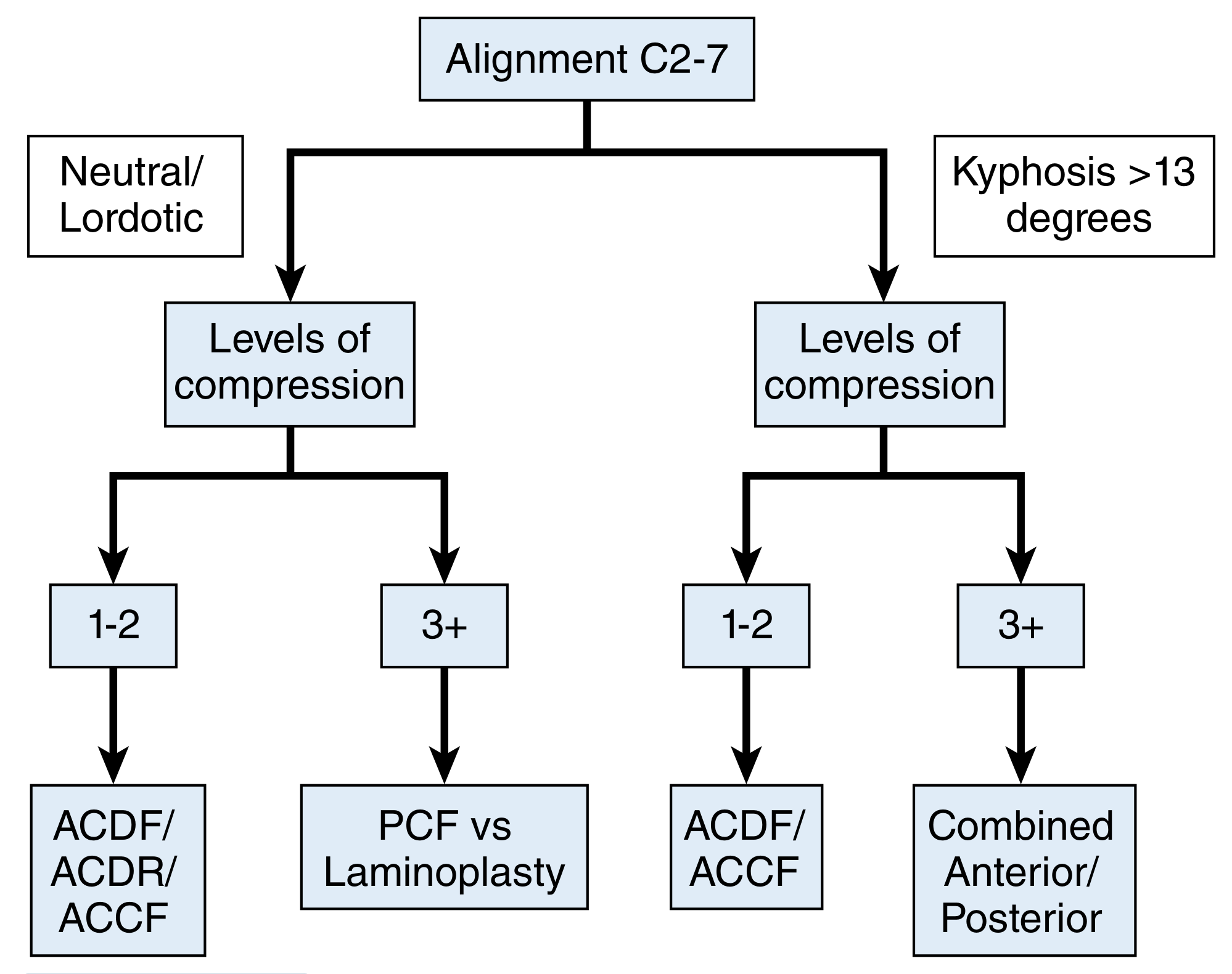
- Alignment: Neutral/lordotic (not kyphotic >13°) → LEFT branch
- Levels of compression: 2 (C5-C6, C6-C7) → "1-2" level branch
- Decision: ACDF / ACDR / ACCF
STEP 6: ANTERIOR CERVICAL DISCECTOMY AND FUSION (ACDF)
Technique - Smith-Robinson Approach (as described in Campbell's, Schmidek & Sweet)
- Supine, slight neck extension (shoulder roll), Mayfield or Gardner-Wells tongs optional
- Head on donut with gentle extension
- Fluoroscopy C-arm positioned for lateral neck views
- Neuromonitoring: MEPs + SSEPs mandatory
- Transverse or oblique incision along anterior border of SCM - usually left side (protects RLN)
- Divide platysma in line with incision
- Develop plane between carotid sheath (laterally) and trachea/esophagus (medially)
- Identify anterior surface of vertebral body through prevertebral fascia
- Divide anterior longitudinal ligament at disc level; place Caspar distraction pins in vertebral bodies above and below
- Distract to restore disc height
- Incise annulus with #15 blade
- Remove disc material with pituitary rongeurs and curettes
- Identify and resect posterior annulus and PLL (especially for central disc-osteophyte complex)
- Decompress both nerve roots by extending decompression laterally to the uncinate processes
- Limit lateral dissection to ~3-4 mm lateral to midline each side (vertebral artery protection)
- Remove posterior osteophytes with high-speed drill or Kerrison rongeur under microscopic visualization
- Iliac crest autograft (gold standard - Smith-Robinson technique) OR PEEK cage with bone graft/BMP
- Anterior cervical plate spanning both levels with locking screws
- Fusion rates: single level ~95%, two-level ~90%
- Dysphagia in up to 90% (most transient, <1% persists >3 months)
- Hoarseness (RLN stretch/injury)
- Adjacent segment disease: ~3% per year (26% per decade) - important counselling point
STEP 7: ALTERNATIVE PROCEDURES
Posterior Cervical Foraminotomy (for lateral disc / foraminal stenosis)
- Best for: soft lateral disc herniation or isolated foraminal stenosis
- Not ideal here: because pathology is central disc-osteophyte complex
- Keyhole foraminotomy: 4-5 mm medial facet resection, adequate root decompression
- Can be done open (Scoville technique) or minimally invasive (Ruetten endoscopic technique per Campbell's)
- Advantages: no fusion required, motion preserved
- Disadvantage: cannot address central stenosis or kyphosis
Posterior Cervical Laminectomy + Fusion (PCF)
- Preferred when: ≥3 level disease with lordosis, or posterior compression dominant
- Lateral mass screws (C3-C6) + pedicle screws (C7-T1) + rods
- Laminectomy from C3 or C4 to C7
Laminoplasty (Open-Door / French-Door)
- Preferred when: ≥3 levels, lordosis preserved, OPLL
- Hirabayashi open-door technique: hinged on one side (typically right), miniplates hold the door open
- Motion preserving but limits neck extension range of motion
Anterior Cervical Corpectomy + Fusion (ACCF)
- Used when: posterior longitudinal ligament ossification (OPLL), multisegment bridging osteophytes
- Entire vertebral body removed (C5 or C6), strut graft + plate reconstruction
- More destabilizing - requires longer plate construct
STEP 8: COMPLICATIONS TO COUNSEL
| Complication | Rate | Notes |
|---|---|---|
| Dysphagia | Up to 90% early, <1% persistent | Most common |
| Hoarseness / RLN palsy | ~3-5% | Usually transient |
| C5 palsy | ~5% | Deltoid weakness post-decompression |
| Graft/hardware failure | ~2-5% | Pseudarthrosis |
| Adjacent segment disease | ~3%/year | Long-term concern |
| Vertebral artery injury | <0.5% | Catastrophic |
| Esophageal perforation | Rare | |
| Dural tear / CSF leak | ~1% |
STEP 9: SPECIAL CONSIDERATIONS FOR MULTILEVEL DISEASE
- 2-level ACDF with plate: fusion rate ~90%; technically preserves motion segment anatomy better
- C6 corpectomy (C5-C7 ACCF): simpler decompression, but higher pseudarthrosis risk if plate not used; longer lever arm
- Motion-preserving strategy to reduce adjacent segment stress
- Appropriate for younger patients without significant facet arthropathy
SUMMARY APPROACH FOR THIS CASE
| Step | Action |
|---|---|
| 1. History | Duration, radicular symptoms (C5-C6: lateral arm, thumb; C6-C7: middle finger), myelopathy (gait, sphincter) |
| 2. Examination | Spurling, Hoffman, myelopathy signs, root levels |
| 3. Imaging | CT (done - shows spondylosis C5-C7); MRI cervical spine for cord signal, disc vs osteophyte |
| 4. Neurophysiology | EMG/NCS to confirm radiculopathy levels; baseline MEP/SSEP |
| 5. Conservative trial | If no myelopathy or progressive deficit: 6-8 weeks trial |
| 6. Surgery | 2-level ACDF C5-C6 + C6-C7 with PEEK cage and anterior plate (Smith-Robinson approach, left-sided) |
| 7. Consider | If lordosis preserved and symptoms predominantly myelopathic with ≥3 levels - posterior approach |
Note: MRI is mandatory before surgery to assess cord signal intensity (T2 hyperintensity = poor prognosis), confirm disc-osteophyte vs soft disc, and evaluate posterior compression.