
Anaesthesia equipment -Breathing system,airway management
anaesthesia breathing circuit circle system components
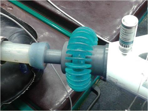
A clinical photograph depicting the assembly of an anesthesia circle system for medication delivery. The central focus is a Y-piece connector facilitating the administration of inhaled salbutamol during general anesthesia. On one end, a transparent corrugated breathing tube is attached via a gray connector. On the opposite side, a metered-dose inhaler (MDI) canister is inserted into a specialized delivery port on a white rigid segment. A distinctive teal-colored, flexible, ribbed adaptor is positioned between the gray cylindrical connector and the delivery port. This setup demonstrates a method for integrating a salbutamol aerosol canister into a closed or semi-closed anesthesia breathing circuit to treat bronchospasm or improve ventilation-perfusion matching during surgical procedures. The photograph illustrates the physical components and mechanical interface required for aerosolized drug delivery in an intraoperative setting.
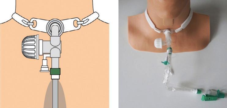
This composite image consists of a technical illustration (left) and a corresponding clinical photograph of a medical manikin (right) demonstrating the Kelley Circuit, a specialized respiratory assembly for tracheostomized patients. The assembly is secured to the neck via a standard tracheostomy tube and neck strap. Key components include a ProTrach XtraCare heat and moisture exchanger (HME) featuring an integrated electrostatic filter, which is attached to the lateral ventilator hub. Connected directly to the ISO 15 hub of the tracheostomy tube is a closed-circuit suction system, visible as a clear, flexible tube partially enclosed in a transparent protective plastic sleeve with green mechanical valves and connectors. This configuration is designed to provide viral and bacterial filtration while allowing for airway clearance without disconnecting the patient from the circuit, thereby reducing the risk of aerosolization and tube drag. It is clinically relevant for critical care and respiratory therapy education, specifically regarding the management of spontaneously breathing patients requiring humidification and frequent suctioning.
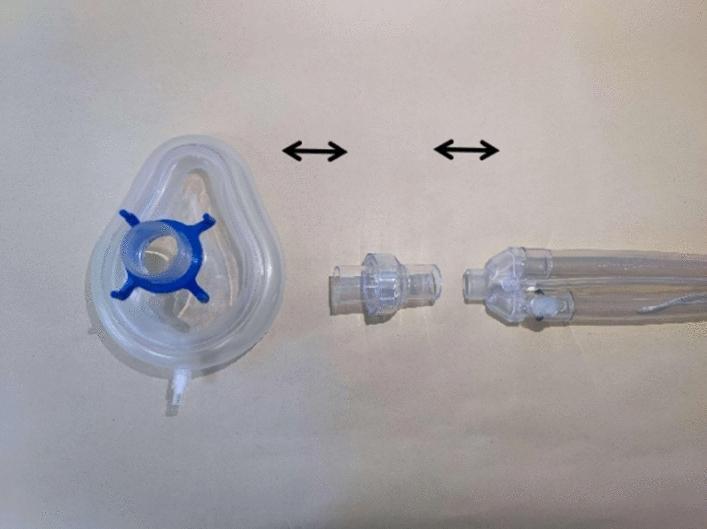
This clinical photograph serves as a schematic diagram illustrating the assembly of a non-invasive high-frequency oscillatory ventilation (NIHFOV) circuit. The image displays three primary medical device components arranged horizontally on a neutral background, with double-ended black arrows indicating the connection sequence. From left to right, the components include: 1) A clear, teardrop-shaped silicone non-invasive ventilation (NIV) mask featuring a blue four-pronged headgear attachment ring and a distal sampling port. 2) A clear, cylindrical disposable leak valve designed to facilitate the venting of exhaled CO2. 3) A proximal segment of a flexible, transparent ventilator breathing circuit showing multi-lumen tubing. The setup demonstrates the critical interface between the ventilator tubing, the mandatory leak valve for safety and gas exchange, and the patient interface (mask). This visual is intended for clinical training and educational instruction on the proper configuration of NIHFOV hardware for respiratory support.
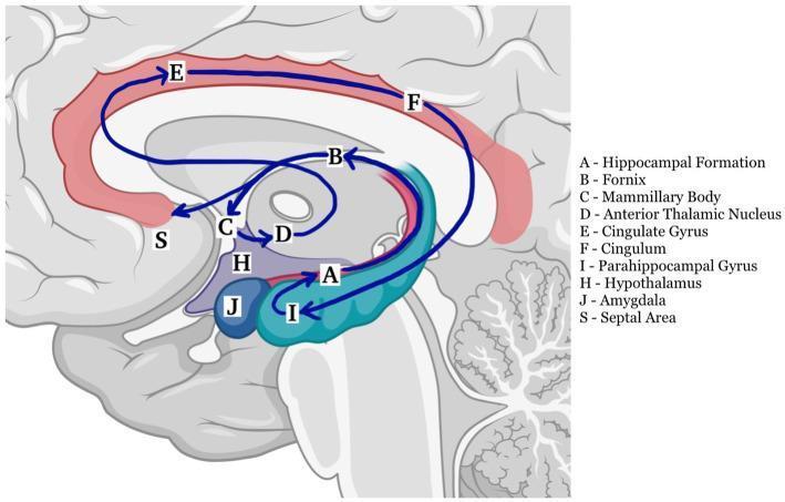
This medical anatomical diagram illustrates the Papez circuit, a fundamental neural pathway of the limbic system involved in memory and emotion. The illustration uses a sagittal view of the human brain to map the connectivity between key structures. The circuit is depicted as a closed loop with directional blue arrows indicating the flow of information. Key components labeled include: (A) Hippocampal Formation, (B) Fornix, (C) Mammillary Body, (D) Anterior Thalamic Nucleus, (E) Cingulate Gyrus, (F) Cingulum, and (I) Parahippocampal Gyrus/Entorhinal Cortex. The pathway follows the sequence: Hippocampus → Fornix → Mammillary bodies → Mammillothalamic tract → Anterior thalamic nucleus → Cingulate gyrus → Cingulum → Entorhinal cortex → Hippocampus. Additionally, adjacent limbic structures are identified, including (H) Hypothalamus, (J) Amygdala, and (S) Septal Area. This educational diagram is designed to demonstrate the functional neuroanatomy and connectivity essential for long-term memory processing and limbic system integration.
Mapleson circuit classification breathing system
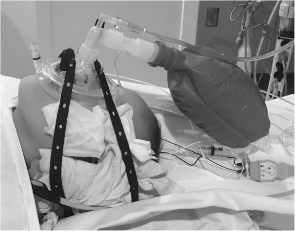
This clinical photograph illustrates a pediatric patient under procedural sedation or general anesthesia, managed with a specialized respiratory circuit. A clear, contoured anesthesia face mask is positioned over the child's nose and mouth, secured firmly by a multi-holed black rubber head strap (Spider strap) to maintain an airtight seal for Continuous Positive Airway Pressure (CPAP). The mask is connected to a Jackson-Rees circuit, a modification of the Mapleson F system, characterized by the visible reservoir bag and fresh gas flow tubing. Key components include an elbow connector at the mask apex, a wide-bore corrugated tube leading to the reservoir bag, and a thin pressure-monitoring line or supplemental oxygen tubing. White gauze padding is placed under the straps near the neck and cheeks to prevent pressure-related skin injury. In the immediate vicinity, a syringe and a medical sensor (likely a pulse oximetry or CO2 monitoring cable) are visible on the sterile field. This setup is clinically used to provide airway support and maintain functional residual capacity (FRC) during radiological procedures or surgery.
This composite image consists of a technical illustration (left) and a corresponding clinical photograph of a medical manikin (right) demonstrating the Kelley Circuit, a specialized respiratory assembly for tracheostomized patients. The assembly is secured to the neck via a standard tracheostomy tube and neck strap. Key components include a ProTrach XtraCare heat and moisture exchanger (HME) featuring an integrated electrostatic filter, which is attached to the lateral ventilator hub. Connected directly to the ISO 15 hub of the tracheostomy tube is a closed-circuit suction system, visible as a clear, flexible tube partially enclosed in a transparent protective plastic sleeve with green mechanical valves and connectors. This configuration is designed to provide viral and bacterial filtration while allowing for airway clearance without disconnecting the patient from the circuit, thereby reducing the risk of aerosolization and tube drag. It is clinically relevant for critical care and respiratory therapy education, specifically regarding the management of spontaneously breathing patients requiring humidification and frequent suctioning.
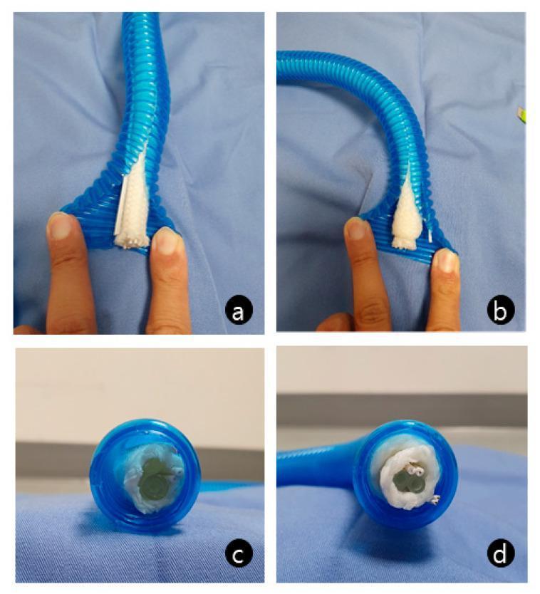
A comparison of a normal (a, c) and a defective (b, d) heated, humidified breathing circuit. The images show a corrugated, translucent blue plastic tube used in anesthesia and intensive care. Inside the circuit, an internal assembly containing a heating wire, temperature sensor, and fluid tubing is wrapped in a white cotton-like insulating material. In the normal circuit (a, c), the cotton wrapping is thin and uniform, preserving a clear patent lumen for airflow. In the obstructed circuit (b, d), which represents a manufacturing error, the white cotton material is irregularly thick and bulky, almost completely occluding the internal diameter of the tube. This visual demonstration highlights a critical equipment-related cause of difficult ventilation, where high circuit resistance due to internal lumen obstruction can lead to nearly undetectable end-tidal CO2 and low tidal volumes despite high pressure settings.
endotracheal tube intubation laryngoscopy airway

This sequence of clinical images demonstrates the four steps of endotracheal intubation (ETI) using a polycarbonate barrier box on an airway trainer manikin. The setup is designed to minimize aerosol exposure during airway management. Step 1: An operator wearing personal protective equipment (PPE), including blue gloves, inserts hands through the rear access ports of the transparent box to begin laryngoscopy. Step 2: The operator uses a Macintosh blade laryngoscope to visualize the glottis while an assistant provides a 7.0 mm cuffed endotracheal tube through a side port. Step 3: The operator inserts the tracheal tube into the trachea. Step 4: The tube is secured, the cuff is inflated, and an Ambu-Bag (manual resuscitator) is connected to begin positive-pressure ventilation. The images highlight the ergonomic constraints and procedural adjustments required when performing direct laryngoscopy within a confined barrier enclosure, commonly utilized in protocols for highly infectious respiratory diseases such as COVID-19.
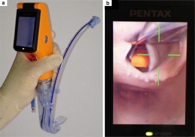
This composite image illustrates the design and clinical application of the Airway Scope® (AWS), a portable, battery-operated video-laryngoscope used for endotracheal intubation. Figure A shows the device's physical components: an orange handle with an integrated 6.1 cm LCD monitor and a single-use 'Intlock' blade. An endotracheal tube (ETT) with a blue radiopaque stripe is preloaded into the blade’s dedicated side-channel guide, which facilitates direct advancement into the trachea. Figure B demonstrates the device's functional output during indirect laryngoscopy. The LCD screen displays a real-time view of the upper airway, specifically focusing on the glottic opening. To assist the clinician, a green crosshair target is superimposed on the digital image; alignment of this target with the glottis indicates the correct path for ETT insertion. This visual aid is designed to simplify intubation by providing a wide viewing angle (180°) and clear anatomical visualization of the vocal cords, thereby potentially increasing first-pass success rates in both novice and expert practitioners.
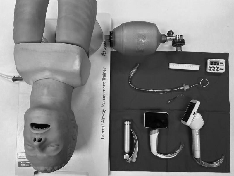
A high-angle clinical photograph displays standard and advanced airway management equipment for endotracheal intubation, positioned alongside a Laerdal Airway Management Trainer mannequin. The equipment includes three types of laryngoscopes: a conventional Macintosh-style laryngoscope with a metal handle and curved blade, and two video laryngoscopes featuring integrated digital screens and specialized curved blades for enhanced glottic visualization. Also present is a Bag Valve Mask (BVM) for manual ventilation. Centrally located is a clear cuffed endotracheal tube (ETT) with an internal stylet bent into a 'hockey-stick' configuration to facilitate insertion; the ETT includes a visible pilot balloon, connector, and depth markings. Ancillary procedural tools include a ruler for measurement and a digital timer for monitoring intubation time. This setup is typical for anesthesia training, emergency medicine simulation, or comparative studies between direct and video laryngoscopy techniques.
Anaesthesia Equipment: Breathing Systems & Airway Management
PART 1: BREATHING SYSTEMS
Overview
- Insufflation / Open drop (historical)
- Mapleson circuits (A-F) - semi-open/semi-closed
- Circle system - closed or semi-closed
- Resuscitation bags (AMBU)
1. Mapleson Circuits
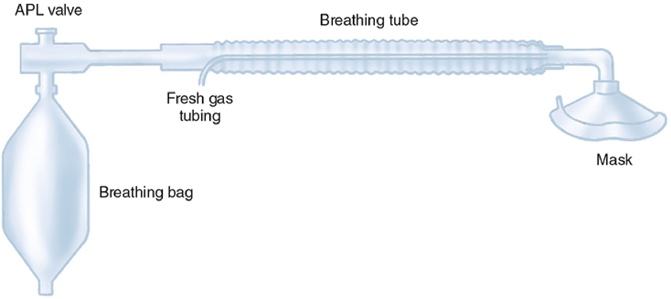
| Circuit | Description | Best For | FGF Required |
|---|---|---|---|
| A (Magill) | APL valve near patient, FGI near bag | Spontaneous ventilation | = Alveolar MV |
| B | FGI near APL, both near patient | Rarely used | High |
| C | FGI and APL close together | Short procedures | High |
| D (Bain) | FGI near patient, APL near bag | Controlled ventilation | 2-3x MV |
| E (Ayre's T-piece) | No bag, no valve - T-piece | Paediatrics | High |
| F (Jackson-Rees) | Open-tailed bag added to E | Paediatrics | High |
- Mapleson A is most efficient for spontaneous ventilation (FGF = minute ventilation).
- Mapleson D/Bain is most efficient for controlled ventilation (FGF = 2-3x minute ventilation).
2. The Circle System
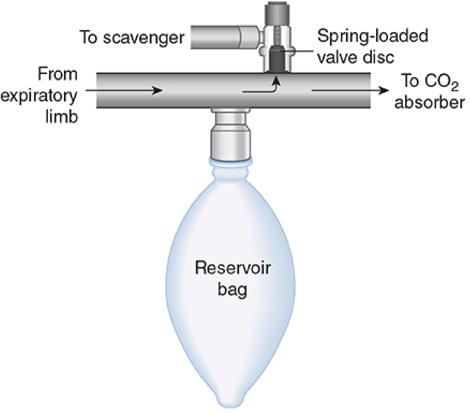
Components of the Circle System
| # | Component | Function |
|---|---|---|
| 1 | Fresh gas inlet | Delivers O₂ + anaesthetic from machine |
| 2 | Inspiratory unidirectional valve | Ensures one-way flow to patient |
| 3 | Corrugated breathing tubes | Connect Y-piece to valves |
| 4 | Y-piece | Patient connection point |
| 5 | Expiratory unidirectional valve | Ensures one-way flow from patient |
| 6 | APL (pop-off) valve | Vents excess gas to scavenger; adjustable |
| 7 | Reservoir bag | Accommodates tidal volume, allows manual ventilation |
| 8 | CO₂ absorber (soda lime) | Chemically absorbs exhaled CO₂ |
CO₂ Absorber Chemistry (Soda Lime)
CO₂ + H₂O → H₂CO₃
H₂CO₃ + 2NaOH → Na₂CO₃ + 2H₂O + Heat
Na₂CO₃ + Ca(OH)₂ → CaCO₃ + 2NaOH
- A pH indicator dye (ethyl violet) changes from white → purple as the absorbent is exhausted.
- Granule size is 4-8 mesh (balance between surface area and airflow resistance).
- Dry soda lime degrades volatile agents - desflurane produces the most carbon monoxide; sevoflurane can produce Compound A.
Optimal Component Arrangement
- Unidirectional valves near patient (prevent backflow; not at Y-piece).
- Fresh gas inlet between absorber and inspiratory valve.
- APL valve between absorber and expiratory valve, near reservoir bag.
- Reservoir bag in expiratory limb (decreases exhalation resistance).
Performance Characteristics
| Feature | Details |
|---|---|
| FGF requirement | ≤1 L/min with absorber; closed-system possible |
| Dead space | Limited to Y-piece (unidirectional valves eliminate tube dead space) |
| Resistance | Increased by valves and absorber; still safe for neonates |
| Heat/humidity | Conserved at low flows; CO₂ granules generate heat |
| Bacterial contamination | Bacterial filters recommended at Y-piece or in limbs |
Disadvantages of Circle System
- Larger, less portable
- Greater complexity - higher risk of disconnection/malfunction
- Absorbent-related complications (CO, Compound A)
- Unpredictable inspired concentrations at low FGF
Monitoring Components in the Circle System
- Oxygen analyzers (Clark electrode / galvanic / paramagnetic): must be present during all GA; sensor placed in inspiratory or expiratory limb; paramagnetic type is self-calibrating.
- Spirometers (Wright respirometer): measure exhaled tidal volume; placed near expiratory valve; under-read at low flows, over-read at high flows.
- Capnography: measures end-tidal CO₂; gold standard for confirming circuit integrity and tracheal tube position.
3. Resuscitation Bags (AMBU / Bag-Mask Unit)
PART 2: AIRWAY MANAGEMENT
Physiological Basis
- Maintain a patent airway
- Ensure adequate ventilation
- Protect lungs from aspiration
Airway Management Progression
- Head-tilt / chin-lift: extends atlanto-occipital joint, lifts tongue off posterior pharynx
- Jaw thrust: displaces mandible anteriorly, most effective for airway opening
Oropharyngeal Airway (Guedel)
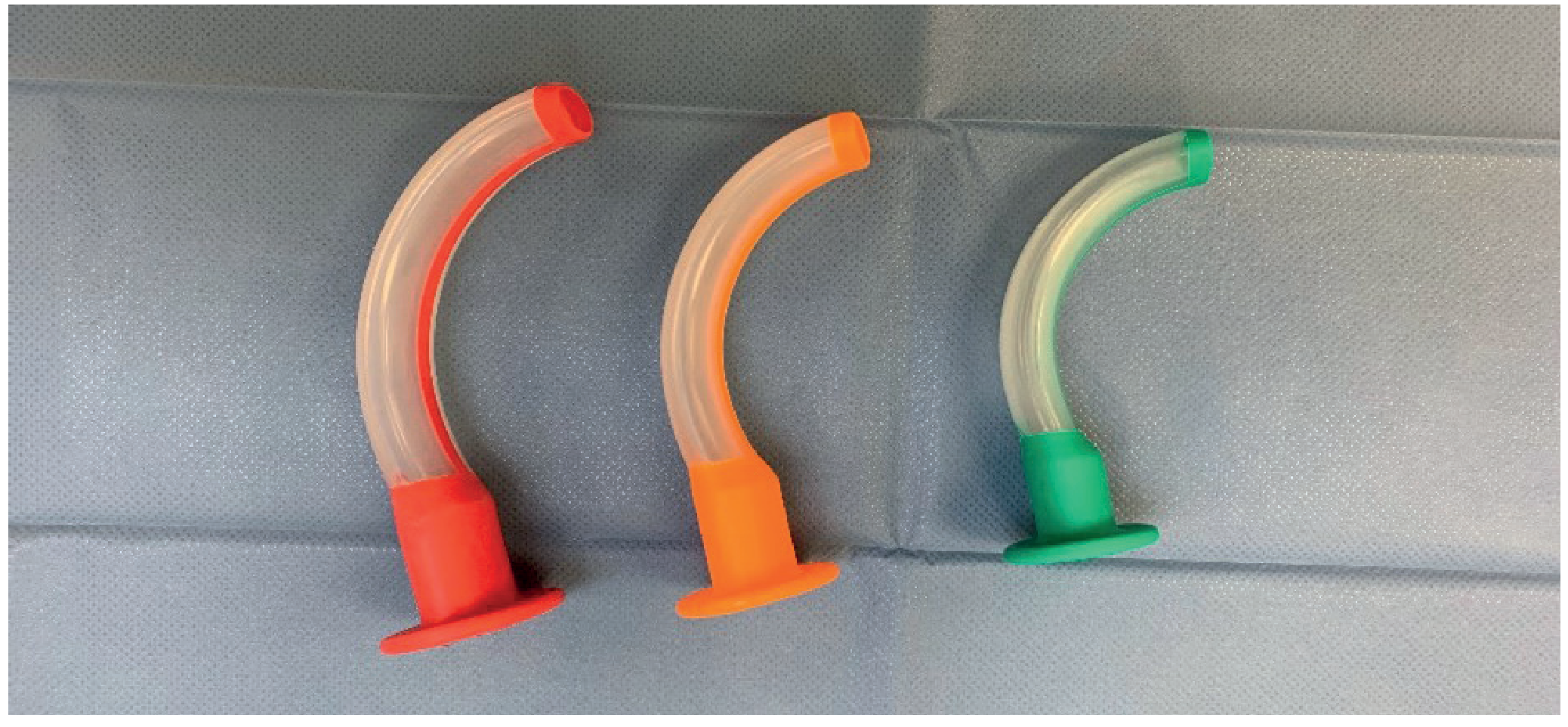
- Curved rigid device; displaces tongue forward
- Available in multiple sizes (measured from centre of mouth to earlobe)
- Holds the tongue forward but does not prevent aspiration
- Requires adequate depth of anaesthesia to tolerate (stimulates gag reflex if awake)
Supraglottic Airway Devices (SADs)
Laryngeal Mask Airway (LMA)
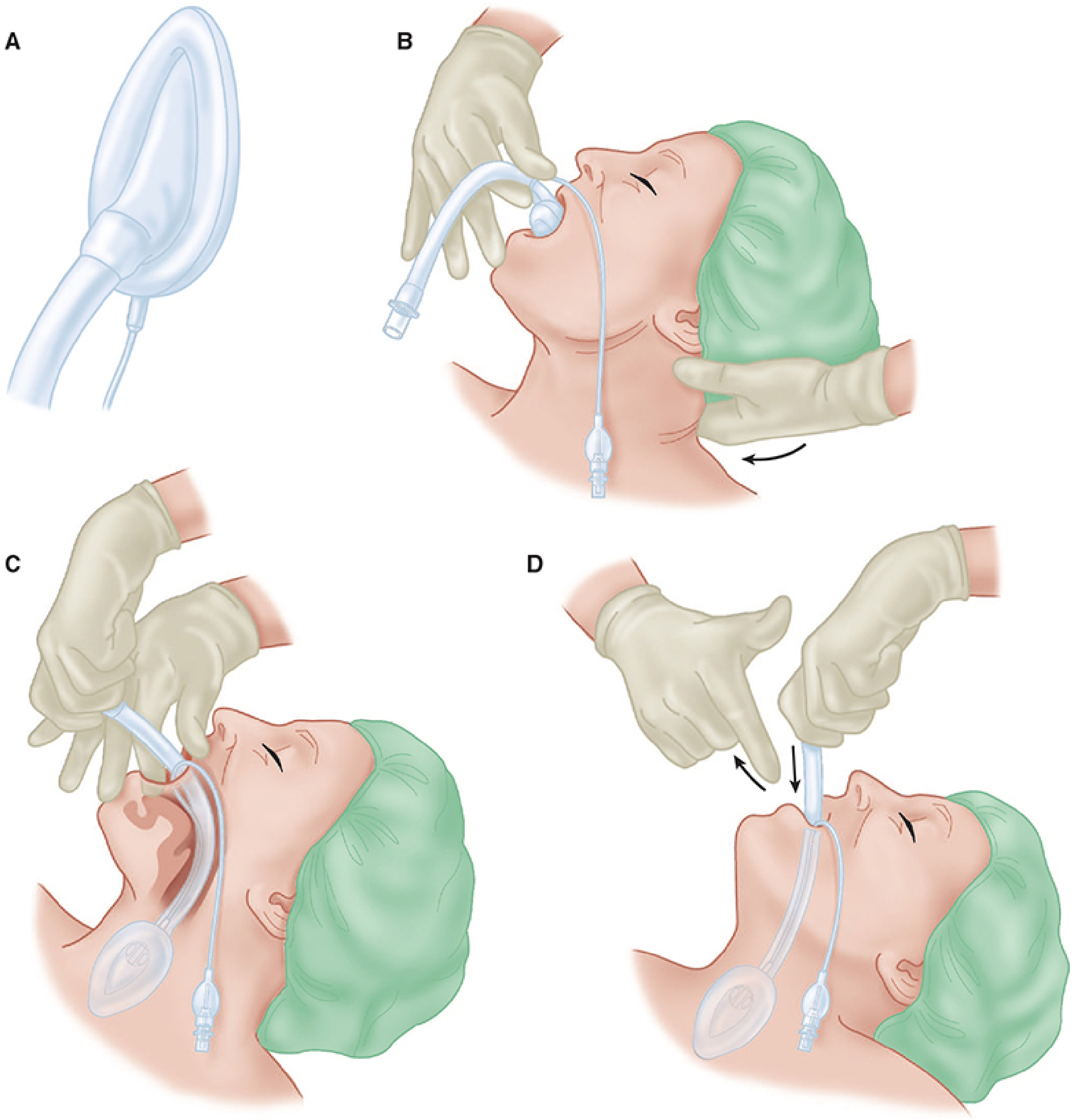
- Base of tongue - superiorly
- Pyriform sinuses - laterally
- Upper oesophageal sphincter - inferiorly
- Choose correct size; check for leaks
- Deflate cuff with rim wrinkle-free, facing away from aperture
- Lubricate only the back of the cuff
- Ensure adequate anaesthesia
- Place patient in sniffing position
- Use index finger to guide insertion along hard palate
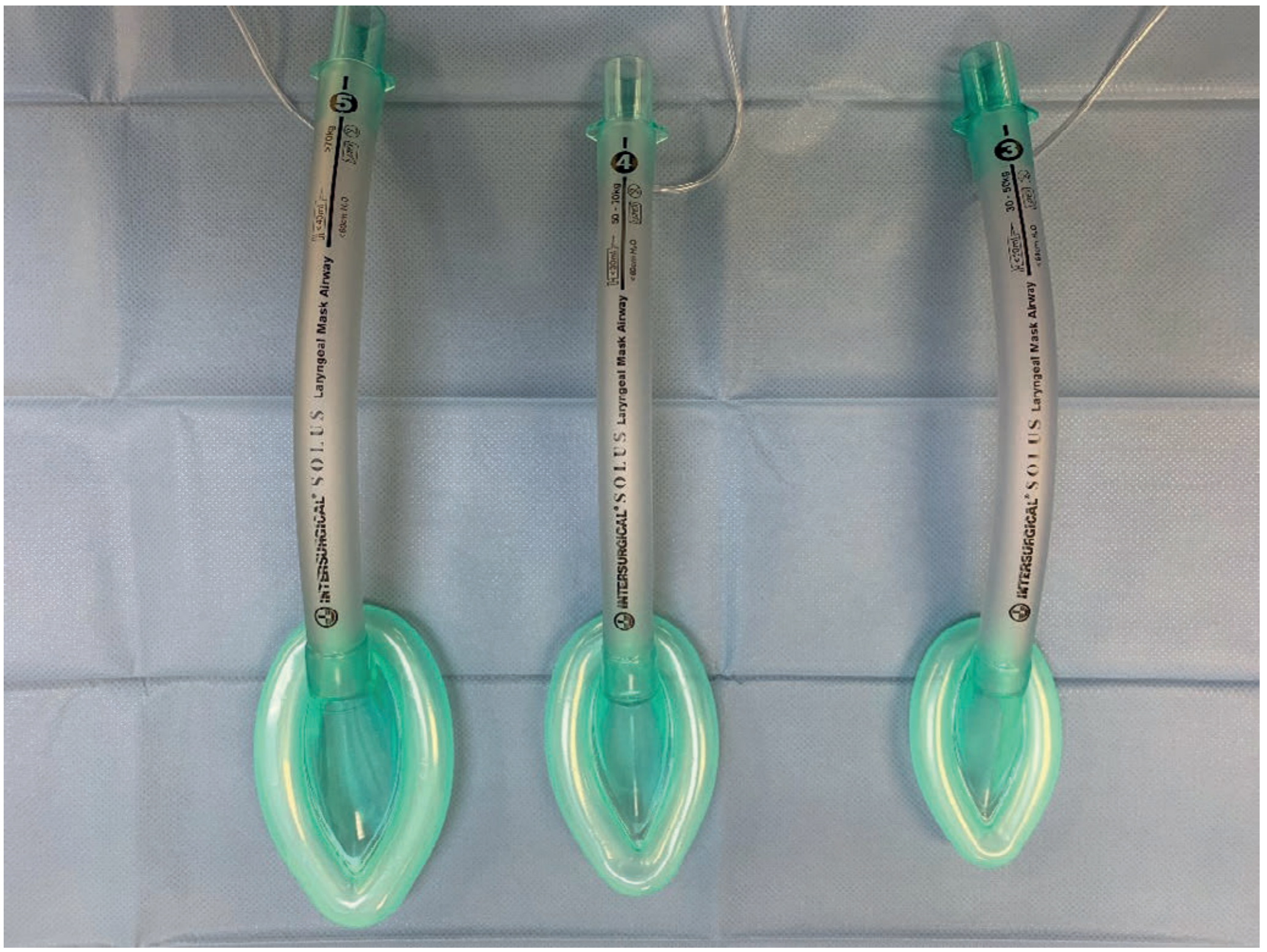
| Size | Patient Weight |
|---|---|
| 1 | Neonates / infants up to 5 kg |
| 1.5 | Infants 5-10 kg |
| 2 | Infants/children 10-20 kg |
| 2.5 | Children 20-30 kg |
| 3 | Small adults 30-50 kg |
| 4 | Adults 50-70 kg |
| 5 | Large adults >70 kg |
- Less invasive than intubation; less haemodynamic response
- Can be taught to non-anaesthetists and paramedics
- Useful as rescue device in "can't intubate" scenario
- Partial protection from pharyngeal secretions (not gastric regurgitation)
- Remove only when patient regains airway reflexes (cough, mouth opening on command)
- Not suitable for high BMI patients (inadequate seal at raised pressures)
- Does not protect against aspiration of gastric contents
- Anatomic variations may prevent adequate seal
LMA Generations and Variants
| Device | Generation | Features |
|---|---|---|
| Classic LMA | 1st | Standard inflatable cuff |
| Flexible LMA | 1st | Reinforced tube for airway surgery |
| ProSeal LMA | 2nd | Oesophageal drain tube; tolerates higher inflation pressures; suitable for higher BMI |
| i-gel | 2nd | Thermoplastic gel cuff (no inflation needed); built-in bite block; oesophageal drain |
| Fastrach (ILMA) | - | Intubating LMA; allows blind tracheal tube insertion |
| LMA CTrach | - | Camera-equipped; facilitates tube passage |
Esophageal-Tracheal Combitube
- Two fused tubes; inserted blindly through the mouth
- Sits in oesophagus ~95% of time; ventilates through side perforations into larynx
- Tracheal placement: use the clear (open-tipped) tube
- Useful in emergency / prehospital settings
King Laryngeal Tube
- Single tube with a small oesophageal balloon and larger hypopharyngeal balloon
- Both inflate via one inflation line; ventilation occurs between the two balloons
- Suction port allows gastric decompression
- If ventilation is poor: tube is likely too deep - withdraw slowly
Endotracheal (Tracheal) Intubation
- Aspiration risk (full stomach, GORD, pregnancy)
- Need for positive pressure ventilation at high pressures
- Procedures requiring muscle relaxation
- Thoracic / abdominal surgery
- Head and neck surgery
- Prolonged operations
- Cuff inflation facilitates positive pressure ventilation
- Protects lungs from aspiration of regurgitated gastric contents
- Cuff pressure should be checked - target 20-30 cmH₂O
- Adult female: 7.0-7.5 mm ID
- Adult male: 8.0-8.5 mm ID
- Paediatric formula: (age/4) + 4 mm (uncuffed); (age/4) + 3.5 mm (cuffed)
- Visualisation through vocal cords
- Bilateral chest expansion
- Auscultation (bilateral air entry, no gastric sounds)
- End-tidal CO₂ (capnography - gold standard)
- SpO₂ maintenance
- Double-lumen tubes / endobronchial tubes: used for thoracoscopic, pulmonary, and oesophageal surgery; allow single-lung ventilation for surgical access; essential in bronchopleural fistula and empyema.
Difficult Airway Management
- Look externally (beard, obesity, small mouth)
- Evaluate 3-3-2 rule (mouth opening 3 fingers, hyoid-chin 3 fingers, hyoid-thyroid notch 2 fingers)
- Mallampati score (class III/IV)
- Obstruction (stridor, tumour)
- Neck mobility (limited in ankylosing spondylitis, C-spine injury)
| Device | Description |
|---|---|
| McGrath / C-MAC video laryngoscope | Indirect laryngoscopy with camera; improves glottic view |
| Airtraq | Optical laryngoscope; channel for tube guidance |
| McCoy laryngoscope | Hinged blade tip; useful in anterior larynx |
| Flexible fibreoptic bronchoscope | Gold standard for awake intubation; tube threaded over scope under direct vision |
- Awake with topical local anaesthetic (in anticipated very difficult airway)
- Under GA in anticipated but not critical difficulty
- Cricothyroidotomy: emergency access through cricothyroid membrane; used in "can't intubate, can't oxygenate" scenario
- Tracheostomy: elective surgical airway; preferred for prolonged ventilation
| Technique | Key Feature |
|---|---|
| Chin lift / jaw thrust | Basic; no equipment |
| Guedel (oral) airway | Holds tongue forward; does not prevent aspiration |
| LMA (1st generation) | Low-pressure perilaryngeal seal; easy to insert |
| 2nd generation SAD (ProSeal, i-gel) | Higher sealing pressure; oesophageal drain; preferred |
| Endotracheal tube | Definitive airway; protects against aspiration; allows IPPV |
| Double-lumen tube | Lung isolation for thoracic surgery |
| Fibreoptic intubation | Difficult/anticipated difficult airway; awake technique |
| Cricothyroidotomy | Emergency surgical airway |
Summary Table: Breathing Systems Comparison
| System | FGF Needed | CO₂ absorption | Rebreathing | Portability | Best Use |
|---|---|---|---|---|---|
| Mapleson A | = MV (spont) | No | Minimal | Good | Adult spontaneous ventilation |
| Mapleson D/Bain | 2-3x MV | No | Minimal | Good | Adult/child controlled ventilation |
| Mapleson F (Jackson-Rees) | High | No | Minimal | Excellent | Paediatrics |
| Circle system | ≤1 L/min | Yes (soda lime) | Controlled | Poor | Prolonged adult GA |
| AMBU bag | 100% O₂ | No | No | Excellent | Emergency/resuscitation |
Anaesthesia equipment -Breathing system
Anaesthesia Equipment: Breathing Systems
Introduction
- Deliver O₂ and anaesthetic gases to the patient
- Eliminate CO₂ (by washout or chemical absorption)
- Conserve heat and humidity
- Allow monitoring of ventilation
1. Insufflation
- Used in children who resist face masks during inhalational induction
- Used in ophthalmic surgery under local anaesthesia (to avoid CO₂ accumulation under drapes) - air blown at >10 L/min
- No rebreathing if flow is sufficient
- Cannot control ventilation; inspired concentration is unpredictable due to entrainment of atmospheric air
2. Draw-Over Anaesthesia
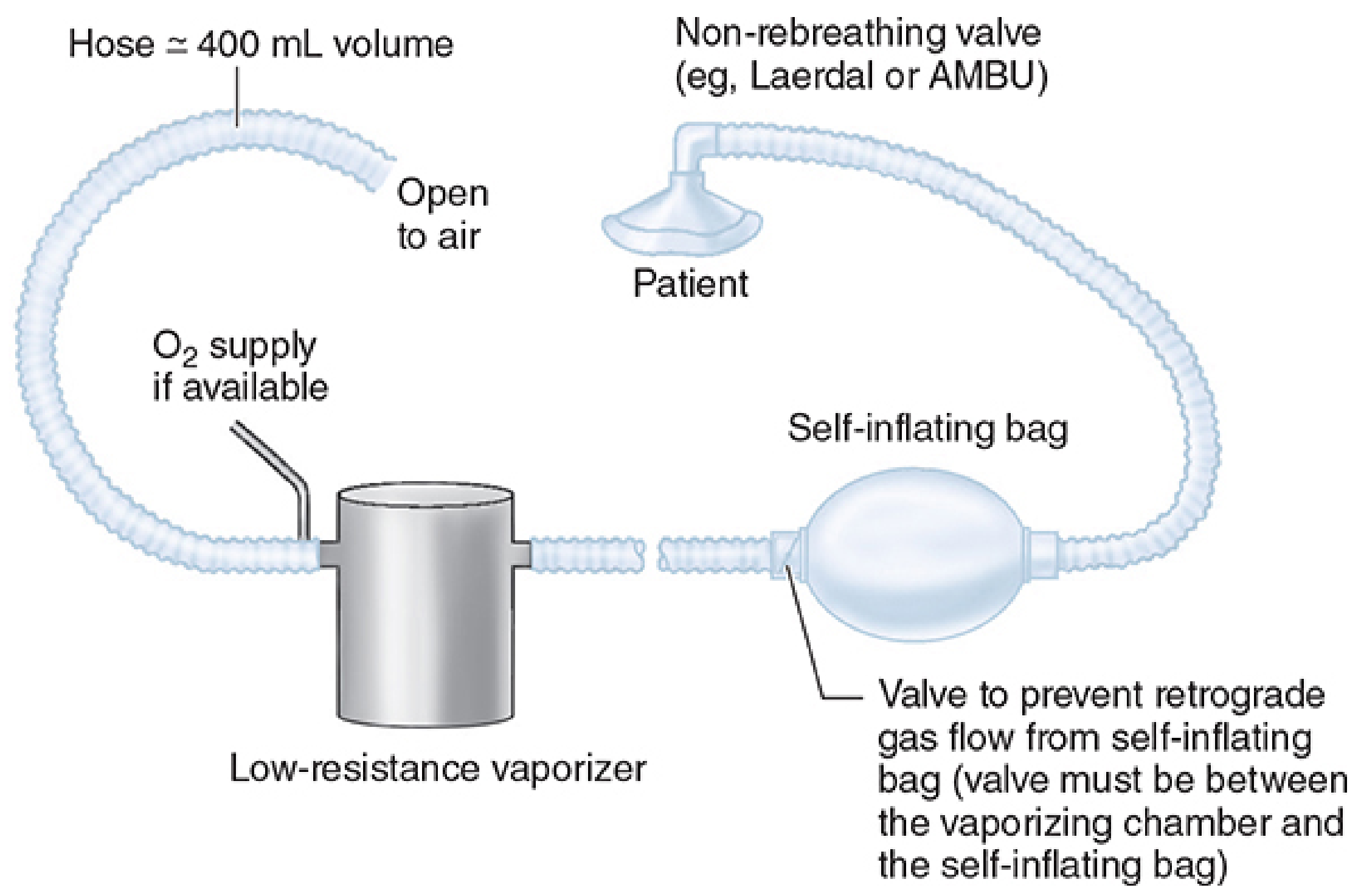
- Portable; no compressed gases required (battlefield, remote settings)
- Non-rebreathing circuit; ambient air is carrier gas
- Supplemental O₂ can be added (1 L/min → FiO₂ 30-40%; 4 L/min → FiO₂ 60-80%)
- Can be adapted for IPPV, CPAP, PEEP
- Patients breathing room air alone often have SpO₂ <90% - supplemental O₂ essential
3. Mapleson Circuits
Components
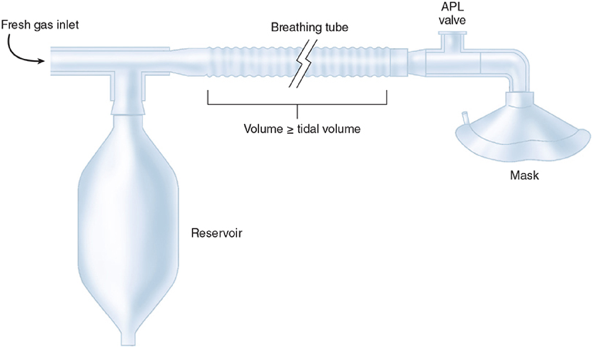
- 22 mm diameter - low resistance
- Volume should be ≥ patient's tidal volume to prevent rebreathing
- High compliance → tidal volume "lost" to circuit during IPPV (e.g., circuit compliance of 8 mL/cmH₂O at 20 cmH₂O = 160 mL lost)
- Continuously delivers O₂ + anaesthetic from the machine
- Its position relative to the APL valve is the key differentiator between Mapleson types
- Also called pop-off valve or pressure-relief valve
- Vents excess gas to the scavenger system
- During spontaneous breathing: kept fully open
- During controlled ventilation: partially closed to build circuit pressure
- Spring-loaded; opening pressure is adjustable
- Acts as gas reservoir between patient breaths
- Allows manual positive-pressure ventilation
- Visual indicator of ventilation (moves with each breath)
- Standard adult size: 2 L
Mapleson Classification Table
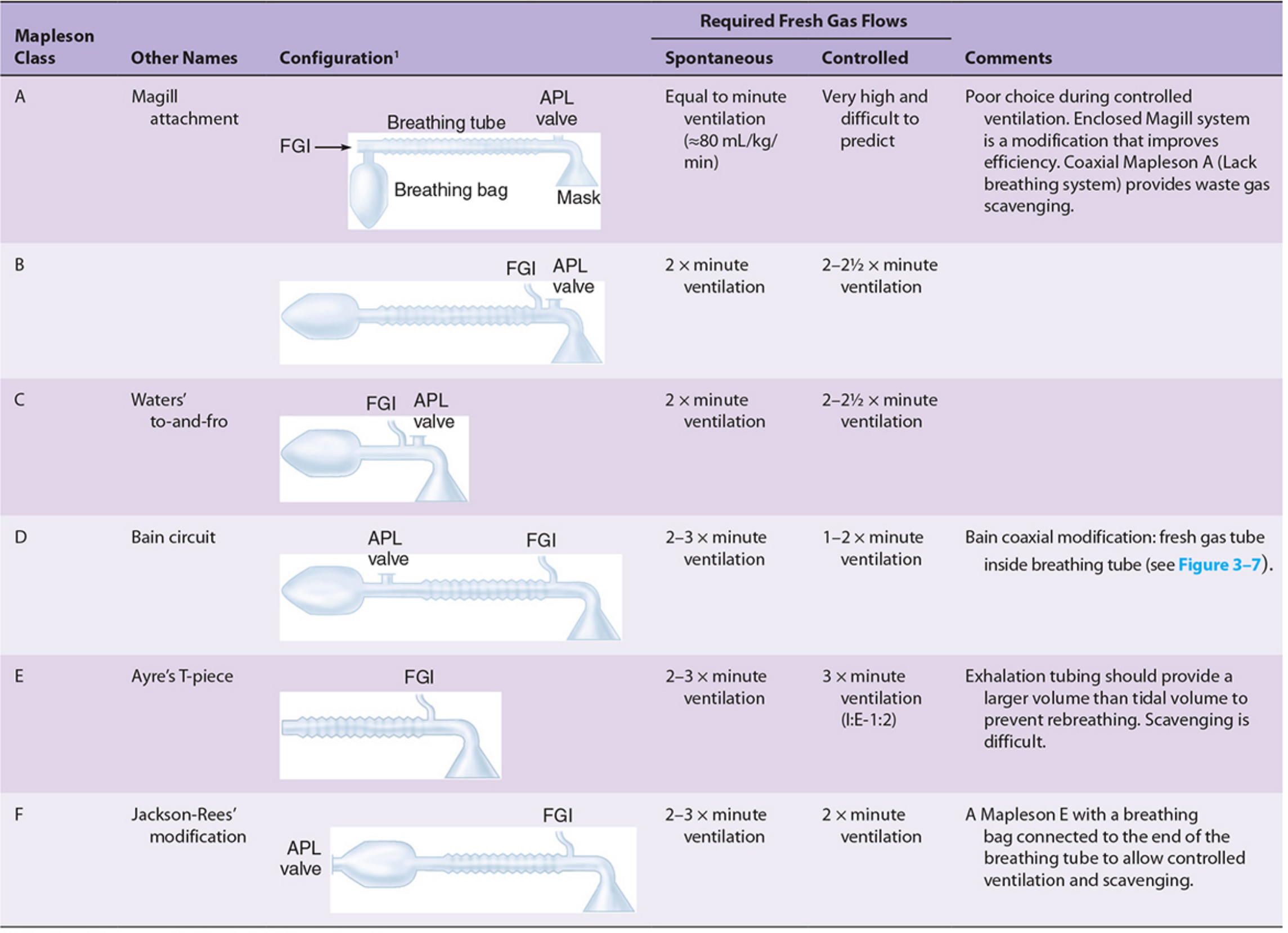
| Circuit | Other Name | FGI Position | APL Position | FGF: Spontaneous | FGF: Controlled | Best Use |
|---|---|---|---|---|---|---|
| A | Magill attachment | Near bag | Near patient (mask end) | = Minute ventilation (~80 mL/kg/min) | Very high, unpredictable | Adult spontaneous ventilation |
| B | - | Near patient | Near patient | 2× MV | 2-2.5× MV | Rarely used |
| C | Waters' to-and-fro | Near patient | Near patient | 2× MV | 2-2.5× MV | Rarely used |
| D | Bain circuit | Near patient | Near bag | 2-3× MV | 1-2× MV | Controlled ventilation |
| E | Ayre's T-piece | Near patient | None (open end) | 2-3× MV | 3× MV | Paediatrics |
| F | Jackson-Rees | Near patient | Bag tail | 2-3× MV | 2× MV | Paediatrics, neonates |
- Mapleson A = most efficient for Spontaneous ventilation (A for Anaesthetist breathing spontaneously)
- Mapleson D = most efficient for Controlled ventilation
The Bain Circuit (Mapleson D Coaxial)
- Fresh gas tubing runs inside the outer corrugated tube (coaxial design)
- FGI at patient end; APL valve and bag at machine end
- Advantages: less bulk; partial heat & humidity conservation by counter-current exchange with expired gases
- Disadvantage: kinking or disconnection of inner tube can cause unrecognised rebreathing - periodic inspection mandatory
- FGF for controlled ventilation: 70 mL/kg/min (or 1-2× MV)
Ayre's T-Piece (Mapleson E) & Jackson-Rees (Mapleson F)
- Ayre's T-piece: No APL valve, no bag. T-shaped connector with FGI on one limb and open expiratory limb. Used in children <20 kg. Scavenging is difficult.
- Jackson-Rees modification: Adds an open-tailed breathing bag to the expiratory limb of the T-piece. Allows controlled ventilation, PEEP, and scavenging. Standard paediatric circuit for infants and neonates.
4. The Circle System
Circle System Diagram
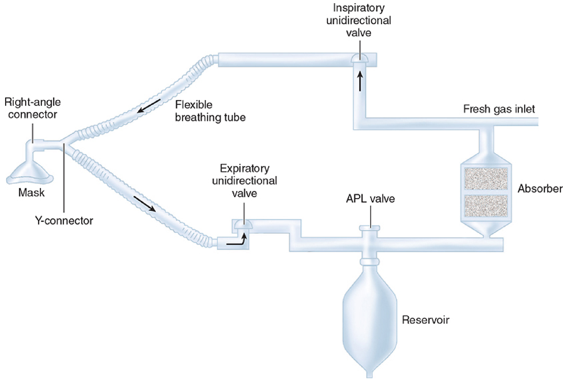
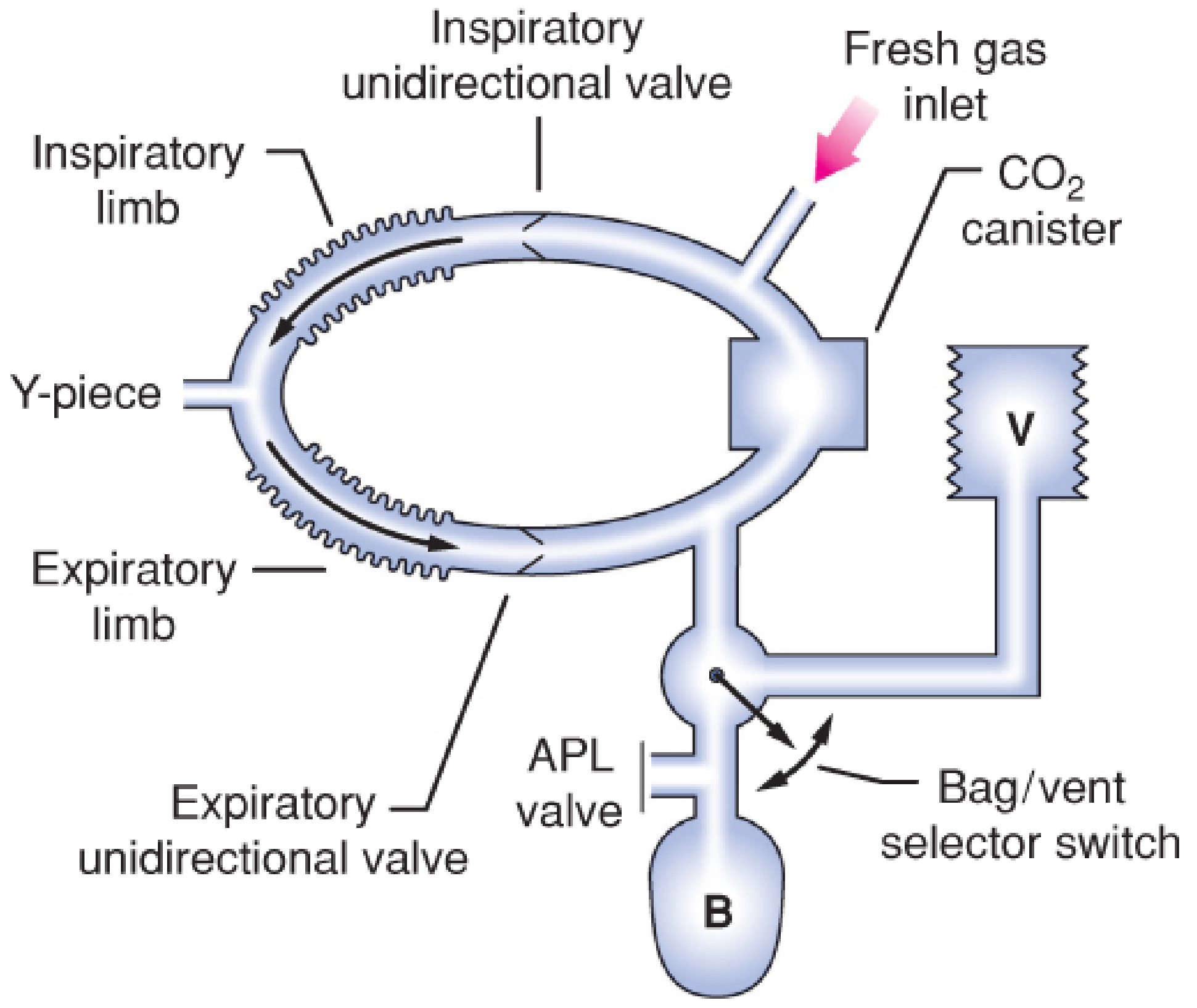
Components
| # | Component | Function |
|---|---|---|
| 1 | Fresh gas inlet | Delivers O₂ + anaesthetic from common gas outlet |
| 2 | Inspiratory unidirectional valve | Directs gas flow toward patient only |
| 3 | Inspiratory breathing tube | Carries fresh + recirculated gas to Y-piece |
| 4 | Y-piece connector | Connects circuit to patient's airway device |
| 5 | Expiratory breathing tube | Carries exhaled gas from Y-piece |
| 6 | Expiratory unidirectional valve | Directs flow away from patient only |
| 7 | APL valve (pop-off valve) | Vents excess gas to scavenger; adjustable spring-loaded |
| 8 | Reservoir bag | Gas storage; visual ventilation monitor; manual IPPV |
| 9 | CO₂ absorber | Chemical neutralisation of exhaled CO₂ |
A. CO₂ Absorber and Soda Lime
- Calcium hydroxide Ca(OH)₂: 80% (main component)
- Sodium hydroxide NaOH
- Potassium hydroxide KOH (small amount)
- Water: 14-19%
- Silica (added to increase hardness, reduce dust)
CO₂ + H₂O → H₂CO₃ (carbonic acid formation)
H₂CO₃ + 2NaOH → Na₂CO₃ + 2H₂O + Heat (fast reaction)
Na₂CO₃ + Ca(OH)₂ → CaCO₃ + 2NaOH (slow reaction)
- Water and NaOH are regenerated - soda lime is self-regenerating to a degree
- End products: heat, water, calcium carbonate (CaCO₃)
- Capacity: 23 L CO₂ per 100 g absorbent
- Granule size: 4-8 mesh (balance between surface area and flow resistance)
- pH indicator dye (ethyl violet): white → purple as absorbent is exhausted
- Replace when 50-70% has changed colour
- Exhausted granules may revert to white on resting, but absorptive capacity does NOT recover
| Agent | Product | Condition |
|---|---|---|
| Desflurane | Carbon monoxide (most) | Dry absorbent |
| Sevoflurane | Compound A (nephrotoxic in animals) | High temperature |
| Isoflurane/Enflurane | Carbon monoxide | Dry absorbent |
- Amsorb (calcium hydroxide + calcium chloride): more inert than soda lime; less volatile agent degradation
B. Unidirectional Valves
- Ensure one-way gas flow through the circuit
- Inspiratory valve: opens on inspiration (gas flows to patient)
- Expiratory valve: opens on expiration (gas flows to absorber)
- Optimal placement: close to patient but NOT at Y-piece (difficult to confirm function at Y-piece)
C. APL Valve
- Spring-loaded valve with adjustable spring tension
- Gas vented to scavenger system (not to atmosphere)
- Manual ventilation: partially close to build circuit pressure
- Spontaneous ventilation: fully open
D. Optimal Component Arrangement
-
Fresh gas inlet → between CO₂ absorber and inspiratory valve
- Downstream of inspiratory valve would waste fresh gas during exhalation
- Between expiratory valve and absorber would dilute gas and interact with soda lime
-
APL valve → between CO₂ absorber and expiratory valve (close to reservoir bag)
- Conserves absorber capacity; minimises venting of fresh gas
-
Unidirectional valves → close to patient
- Prevents backflow if circuit leak develops
-
Reservoir bag → in expiratory limb
- Decreases resistance to exhalation
Performance Characteristics
| FGF | System Mode | Notes |
|---|---|---|
| = Patient O₂ uptake | Closed system | Complete rebreathing; FGF matches consumption only |
| ≤1 L/min | Semi-closed (low flow) | CO₂ absorber essential; economical, heat-conserving |
| 1-5 L/min | Semi-closed (moderate flow) | Most common in practice |
| >5 L/min | Semi-open (high flow) | CO₂ absorber unnecessary; rapid changes in concentration |
- Apparatus dead space = only the volume distal to Y-piece
- Unidirectional valves prevent tube dead space (unlike Mapleson circuits)
- Corrugated tube length does NOT affect dead space (unlike Mapleson), but DOES affect circuit compliance
- Increased by valves and absorber
- Still safe for premature neonates
- Worse at high respiratory rates and large tidal volumes
- High FGF → low relative humidity (fresh gas is cold and dry)
- Low FGF → greater heat and humidity conservation from rebreathing
- CO₂ absorbent granules themselves are a significant source of heat and moisture (exothermic reaction)
- Minimal but theoretically possible
- Bacterial filters recommended at Y-piece, or in inspiratory/expiratory limbs
Modes of the Circle System
| Mode | FGF | Absorber needed | Rebreathing |
|---|---|---|---|
| Semi-open | Very high | No | Negligible |
| Semi-closed | Moderate-low | Yes | Partial |
| Closed | = Uptake only | Yes | Complete (after CO₂ absorption) |
Circle System Monitoring Components
- Mandatory for every general anaesthetic
- Types: Polarographic (Clark electrode), Galvanic (fuel cell), Paramagnetic
- Placed in inspiratory or expiratory limb (not fresh gas line)
- Must have automatic low-level alarm on machine start-up
- Paramagnetic type: self-calibrating, no consumable parts, fast enough to differentiate inspired vs. expired O₂
- Measures exhaled tidal volume
- Placed near expiratory valve
- Common type: rotating vane anemometer
- Errors: under-reads at low flows; over-reads at high flows; water condensation causes errors
- "Exhaled" volumes at expiratory limb include gas that expanded breathing tubes (not delivered to patient)
- Measures end-tidal CO₂
- Confirms circuit integrity, tracheal tube position, and ventilation adequacy
- Normal end-tidal CO₂: 35-45 mmHg
- Absent ETCO₂ indicates oesophageal intubation or circuit disconnection
Disadvantages of the Circle System
- Larger and less portable than Mapleson circuits
- Greater complexity → higher risk of disconnection or malfunction
- CO₂ absorbent-related complications (CO production, Compound A)
- Unpredictable inspired concentrations at low FGF
- Increased resistance from valves and absorber
5. Resuscitation Breathing Systems (AMBU Bag / Bag-Mask Unit)
- Patient valve opens during inspiration → gas flows from bag to patient
- Exhaled gas vented to atmosphere through exhalation ports (no rebreathing)
- Self-refilling compressible bag with intake valve
- Reservoir attached to intake valve prevents room air entrainment
- FiO₂ ∝ O₂ flow rate / minute ventilation delivered
- High FGF needed for high FiO₂
- Exhaled moisture can cause valve sticking
- Exhaled gas vented to environment (infection risk)
- Cannot scavenge waste anaesthetic
Comparison of All Breathing Systems
| System | Complexity | FGF Required | CO₂ Removal | Rebreathing | Heat/Humidity | Portability | Best Use |
|---|---|---|---|---|---|---|---|
| Insufflation | Minimal | Very high | Washout | None | No | Excellent | Paediatric induction; ophthalmic surgery |
| Draw-over | Simple | Low | Washout | None | No | Excellent | Remote/battlefield; no compressed gas |
| Mapleson A | Simple | = MV (spont) | Washout | Minimal | No | Good | Adult spontaneous ventilation |
| Mapleson D/Bain | Simple | 1-2× MV (ctrl) | Washout | Minimal | Partial | Good | Adult/paediatric controlled ventilation |
| Mapleson E/F | Simple | 2-3× MV | Washout | Minimal | No | Excellent | Neonates and infants |
| Circle (low flow) | Complex | ≤1 L/min | Soda lime | Controlled | Yes | Poor | Prolonged adult GA; low-flow/closed |
| AMBU bag | Simple | High | None | None | No | Excellent | Emergency; resuscitation |
Clinical Pearls
- The circle system is the standard for adult GA in theatre; low-flow anaesthesia (≤1 L/min) is economical and environmentally responsible.
- Mapleson A requires only MV during spontaneous breathing - the most efficient semi-open circuit for this purpose.
- Bain circuit inner tube disconnection causes rebreathing - test by occluding inner tube with a finger (Pethick test): if flow stops at rotameter it is patent.
- Soda lime exhaustion presents as rising ETCO₂ despite adequate ventilation.
- Dry soda lime degrades desflurane to CO most readily - check absorbent is not desiccated after machine has been idle.
- High FGF (>5 L/min) in circle system: allows rapid changes in delivered anaesthetic concentration (useful for induction and emergence); CO₂ absorber is not needed.