
Pulled elbow
pulled elbow nursemaid elbow radial head subluxation reduction technique
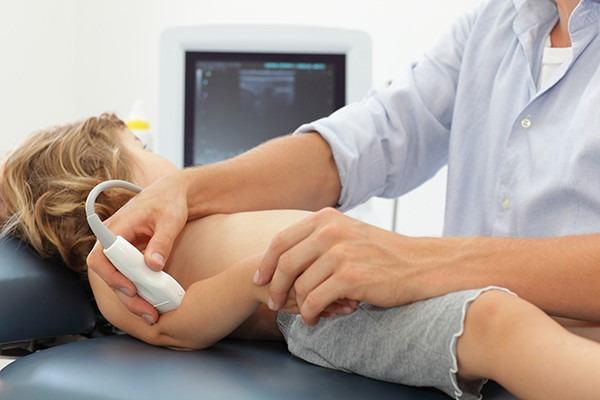
This clinical procedural photograph demonstrates the point-of-care ultrasound (POCUS) technique for diagnosing a 'pulled elbow' (radial head subluxation) in a pediatric patient. The child is positioned supine on a medical examination table with the head turned laterally. A medical professional is seen applying a high-frequency linear ultrasound transducer to the posterior-lateral aspect of the patient's elbow joint. The probe is oriented caudally to visualize the radiohumeral joint and the annular ligament. In the background, an ultrasound monitor displays a real-time grayscale musculoskeletal image. This procedure is used in pediatric emergency medicine to identify signs such as an increased distance between the radial head and the humerus capitate or the interposition of the annular ligament, which confirms subluxation. The image illustrates proper hand placement for stabilizing the young patient's limb while manipulating the transducer to achieve diagnostic views.
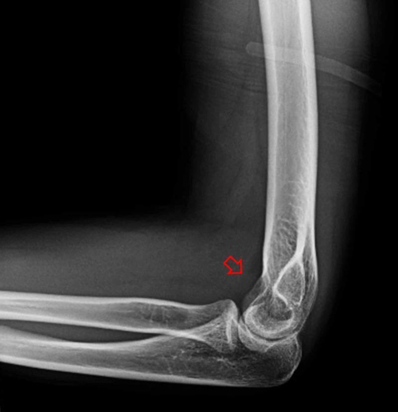
This diagnostic image is a lateral X-ray of a human elbow joint following procedural reduction of a radial head dislocation and elbow subluxation. The radiograph demonstrates restored anatomical alignment: the radial head is congruent with the humeral capitellum, and the ulnohumeral articulation appears well-positioned. No obvious cortical fractures or avulsion fragments are visible in the distal humerus, proximal radius, or ulna. A red arrow points to a subtle, localized area of increased radiopacity within the anterior joint space, suggestive of joint effusion or hemarthrosis. This finding is characterized by a density that is higher than the surrounding soft tissue but significantly lower than the adjacent cortical bone. The image serves as an educational example of post-reduction radiological assessment in emergency orthopedics, highlighting successful joint realignment and secondary signs of intra-articular trauma such as hemarthrosis.
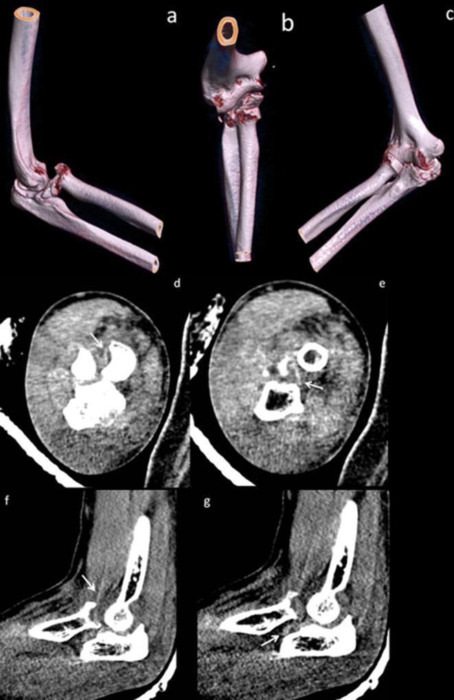
Diagnostic imaging series of the right elbow demonstrating an anteromedial fracture-dislocation of the radial head. Panels (a-c) present volume-rendered 3D CT reconstructions in anterior oblique and anteroposterior views, highlighting a comminuted radial head fracture involving approximately 25% of the articular surface. Small osseous fragments are visible wedged posterior to the radial head and within the radial notch of the ulna. Rotatory subluxation is indicated by the malalignment of the ulnar trochlear notch relative to the humeral trochlea. Panels (d-e) show axial CT slices, and (f-g) show sagittal slices in soft tissue windows. These cross-sectional images identify the brachialis tendon (white arrows) as a linear hyperdensity traversing posterolateral to the radial head fracture site. This anatomical relationship is clinically significant as it illustrates a soft tissue 'sling' effect that can impede manual reduction of the dislocation. The content is suitable for orthopedic and radiology education focusing on complex elbow trauma and the identification of mechanical blocks to reduction.
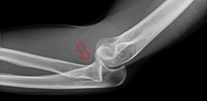
This diagnostic image is a lateral X-ray radiograph of the elbow joint. It demonstrates significant musculoskeletal pathology involving the proximal forearm and distal humerus. The primary finding is a radial head dislocation, where the radial head is displaced anteriorly and is no longer articulating with the capitellum of the humerus. This misalignment is indicated by a red arrow pointing toward the displaced radial head. Additionally, the image shows signs of elbow subluxation, characterized by an incongruous relationship between the trochlear notch of the ulna and the trochlea of the humerus, suggesting partial loss of contact between the joint surfaces. Key anatomical landmarks visible include the distal humeral epicondyles, the olecranon process, and the coronoid process of the ulna. There is no evidence of an acute fracture in this projection. This radiographic study is clinically significant for diagnosing complex elbow injuries and assessing the need for orthopedic reduction. It serves as an educational example of traumatic joint disruption for students and clinicians in emergency medicine and orthopedics.
Pulled Elbow (Nursemaid's Elbow / Radial Head Subluxation)
Definition & Epidemiology
- Tintinalli's Emergency Medicine, p. 953 - 954
- Harriet Lane Handbook, 23rd ed.
Mechanism
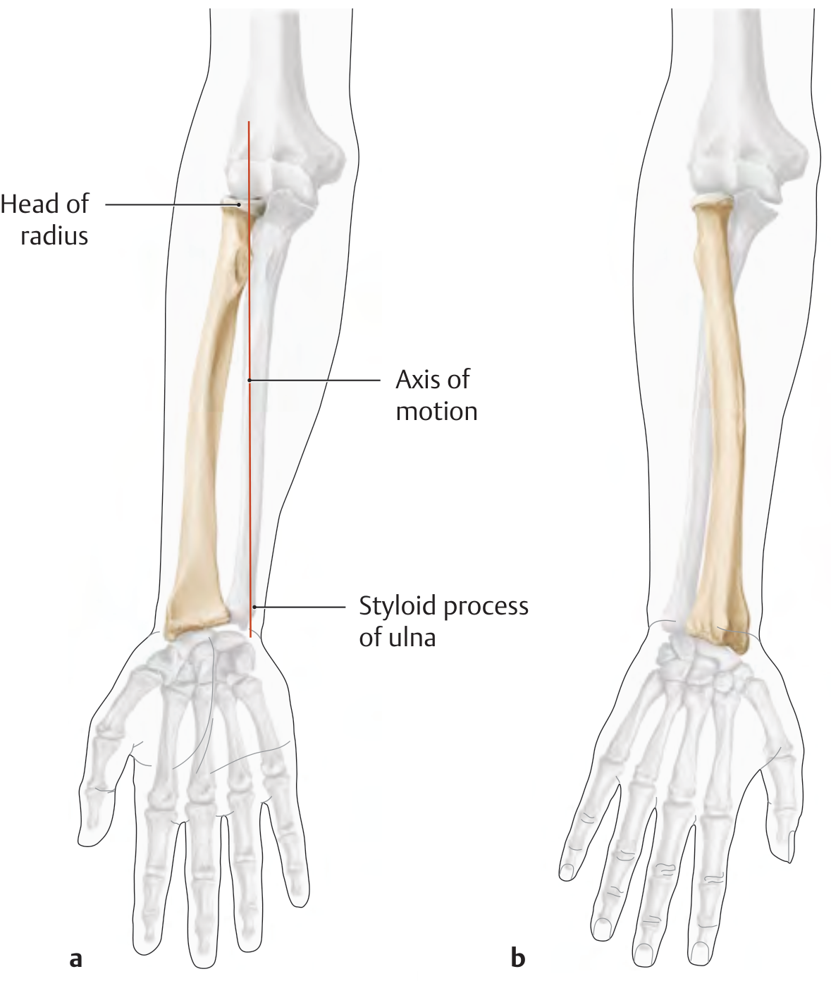
Clinical Presentation
| Feature | Detail |
|---|---|
| Age | 1-4 years (range birth to 6 years) |
| History | Sudden traction on arm, often by a caregiver |
| Arm position | Held in slight flexion and pronation, adducted at side |
| Pain | Sudden acute onset; child refuses to use arm |
| Swelling/bruising | Absent - no focal swelling |
| Tenderness | Over the radial head; significantly increased with pronation/supination |
| Neurovascular exam | Normal |
When to Get Imaging
- Mechanism is atypical or history is inconsistent
- There is focal swelling, bruising, or significant point tenderness suggesting fracture (radial head/neck fracture, supracondylar fracture, bowing fracture)
- Age is outside the typical range
- Reduction attempt fails
Reduction Techniques
- Place your thumb over the radial head laterally, fingers over the epicondyles
- With the other hand, grasp the child's wrist or hand in a handshake grip
1. Hyperpronation (HP) - Preferred
- Forcefully pronate the forearm (turn palm down)
- You may feel or hear a click at the moment of reduction
- The meta-analysis published in 2017 found HP is more effective and less painful than the SF method
2. Supination-Flexion (SF) - Traditional
- Quickly supinate the forearm (turn palm up) with external rotation
- Simultaneously flex the elbow fully
- A click may be felt
After Reduction
- Most children begin to use the arm within 15 minutes, some immediately
- If subluxation was prolonged, recovery may be slower - in that case, immobilise with a posterior splint
- If reduction fails after two attempts, obtain a radiograph and reconsider the diagnosis
- Recurrence is possible; parents should be counselled to avoid lifting the child by the hands or wrists
Differential Diagnosis
| Condition | Distinguishing Features |
|---|---|
| Radial head/neck fracture | Focal tenderness, swelling; X-ray shows fracture |
| Supracondylar fracture | Posterior fat pad sign on X-ray; often more swelling |
| Bowing fracture | Visible on X-ray; tenderness along shaft |
| Monteggia fracture | Ulnar fracture + radial head dislocation |
| Clavicle fracture | Tenderness over clavicle |
| Shoulder injury | Tenderness localised to shoulder |
Blood supply of long bones
blood supply long bone nutrient artery diaphysis epiphysis periosteal vessels diagram
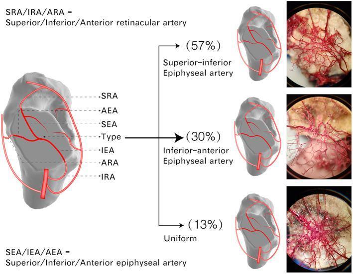
This composite educational graphic details the intraosseous arterial blood supply of the femoral head through anatomical diagrams and microscopic vascular casts. The main illustration labels the key nutrient vessels: Superior (SRA), Inferior (IRA), and Anterior (ARA) Retinacular Arteries, which transition into Superior (SEA), Inferior (IEA), and Anterior (AEA) Epiphyseal Arteries. The graphic identifies three distinct patterns of arterial anastomosis within the femoral head epiphysis: 1. Superior-inferior Epiphyseal artery anastomosis (57%), 2. Inferior-anterior Epiphyseal artery anastomosis (30%), and 3. Uniform anastomosis (13%). Each variation is represented by a schematic illustrating the dominant arterial loops and a corresponding high-magnification photograph of a microscopic vessel cast, showing the intricate, three-dimensional network of small vessels (≥0.05 mm). This visualization highlights the redundancy of the femoral head's blood supply, which is critical for understanding the pathophysiology of femoral neck fractures and avascular necrosis.
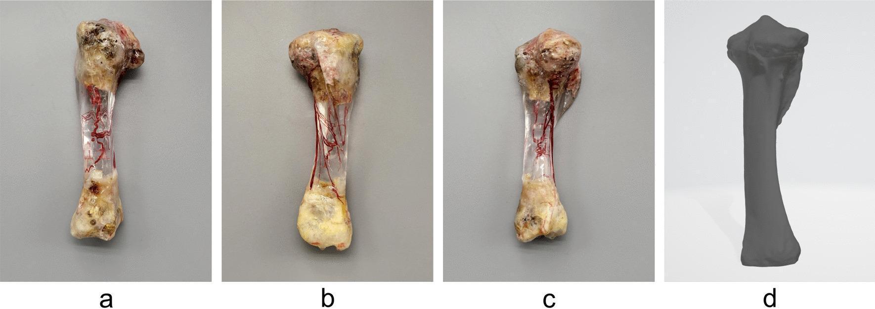
This figure showcases a human tibia specimen prepared using an advanced vascular casting and bone-clearing technique to demonstrate internal intraosseous blood supply. Figures a (rear view), b (side view), and c (front view) display the physical specimen where the cortical bone has been replaced with a transparent epoxy resin. Inside the clear diaphysis, the intraosseous vascular network is clearly visible, highlighted by a red casting agent. The network shows the primary nutrient artery entering the medullary cavity and bifurcating into ascending and descending medullary trunks with subsequent terminal branching toward the proximal and distal metaphyses. The arrangement reveals higher vessel density at the epiphyses compared to the mid-shaft. Figure d provides a complementary 3D digital model of the same tibia, illustrating the external anatomical landmarks and surface morphology used for resin mold construction. This anatomical demonstration is crucial for orthopedic surgical planning, particularly in understanding bone vascularization and nutrient foramen localization.
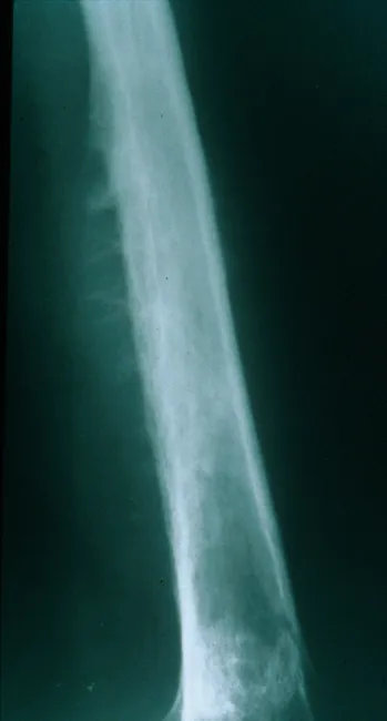
Plain Radiography of a long bone diaphysis demonstrates an aggressive, ill-defined osteolytic lesion with cortical destruction and periosteal reaction. The radiograph shows a moth-eaten destruction pattern with diffuse bone loss extending along a substantial portion of the shaft. Periosteal elevation produces Codman triangle in the swept cortex, while layered deposition of reactive new bone beneath the periosteum can create an onion-skin appearance; in some cases perpendicular radiating spicules or sunburst-like projections may be seen. The lesion often breaches the cortex or expands to form a soft tissue mass that extends beyond the bone. Although ultrasound or CT can delineate the soft tissue component, CT and MRI best characterize the extent, relation to surrounding structures, and marrow involvement. The radiographic pattern is highly suggestive of an aggressive small round blue cell tumor, most notably Ewing sarcoma, particularly in children and adolescents. Differential considerations include osteosarcoma, osteomyelitis, lymphoma, metastasis, or eosinophilic granuloma, but the combination of an diaphyseal, permeative lesion with onion-skin periosteal reaction strongly favors Ewing. Clinical correlation with pain, fever, raised inflammatory markers, and prompt biopsy is essential to confirm diagnosis and guide treatment, which typically combines chemotherapy, limb-sparing surgery, and possibly radiotherapy.
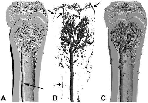
This composite of three 3D surface-rendered models (A, B, and C) illustrates the spatial relationship between bone macrostructure and microvasculature, likely in a mammalian femur model. Panel A shows an undecalcified bone model displaying the cortical shaft, marrow cavity, and trabecular network in the metaphysis. A central medullary artery (arrow) is visible running longitudinally. Panel B depicts the vascular cast alone after decalcification, highlighting the nutrient artery, its primary branches, and a dense network of sinusoid capillaries within the metaphysis. External arrows point to the periosteal arteries and branched peripheral networks. Panel C demonstrates the over-imposition of both models, utilizing pseudo-coloring to differentiate the calcified bone matrix (lighter gray) from the internal and external vascular systems (darker gray). The imaging modality is micro-computed tomography (µCT) with vascular contrast agents, designed to study bone-vessel interactions, such as those occurring in normal physiology or pathological states like metastasis or osteolysis. The visualization highlights anatomical regions including the diaphysis, metaphysis, and epiphysis.
Blood Supply of Long Bones
Overview Diagrams
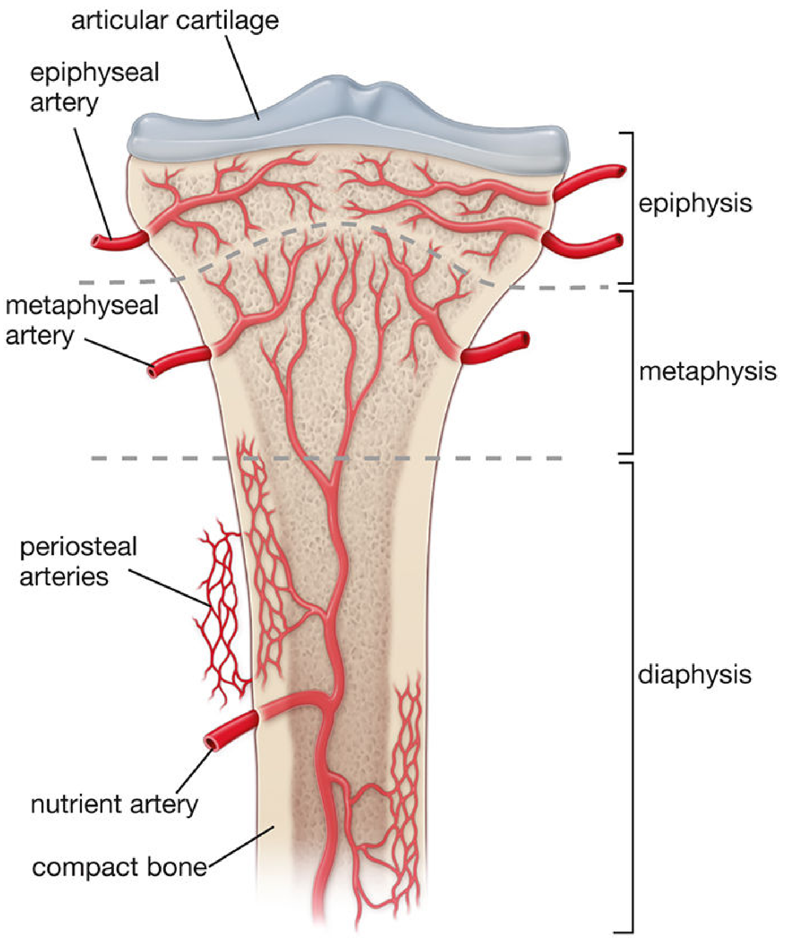
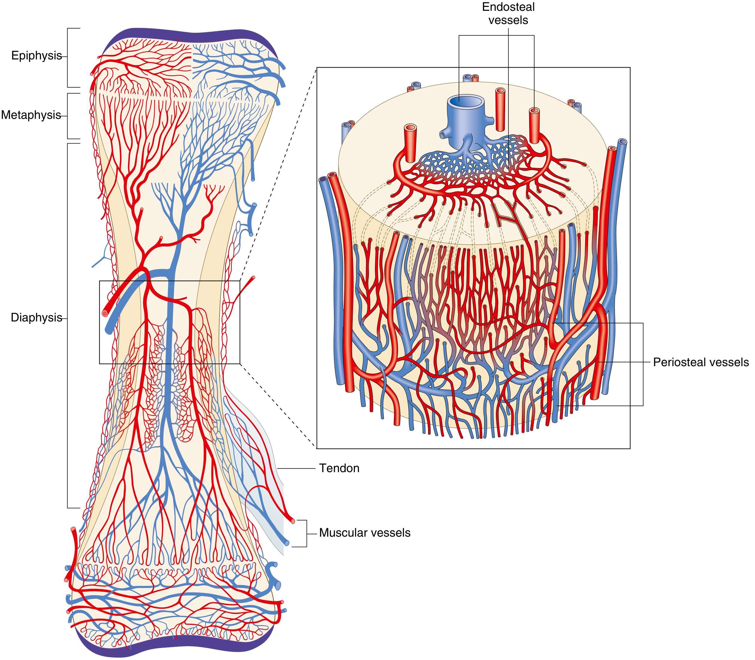
1. Nutrient Artery System (Diaphyseal Supply)
- High-pressure system - the dominant supply to the diaphysis
- Supplies approximately 60% of cortical bone vascularization
- A branch from a named systemic artery (e.g., brachial artery for the humerus) enters the diaphyseal cortex through the nutrient foramen and nutrient canal
- Once inside the medullary cavity it bifurcates into ascending and descending medullary trunks, which run toward the metaphyses
- These branch further into arterioles in the endosteal cortex, supplying the inner two-thirds of the mature diaphyseal cortex via the Haversian (osteon) system
The nutrient foramina arise developmentally as pathways of the principal vessels of periosteal buds during ossification.
2. Metaphyseal-Epiphyseal System
- Arises from the periarticular vascular plexus (e.g., geniculate arteries around the knee)
- Epiphyseal arteries enter through separate foramina in the epiphysis and supply the epiphyseal cancellous bone and articular end
- Metaphyseal arteries arise from periosteal vessels that become incorporated into the metaphysis as the bone widens during growth
- These two systems maintain a separate supply either side of the physis (growth plate) in children, which is important because the growth plate itself is avascular - it relies on diffusion from vessels on both sides
3. Periosteal System
- Low-pressure system - supplies the outer third of the mature diaphyseal cortex
- Consists mostly of capillaries running in the periosteum
- These vessels enter cortical bone through Volkmann's canals (transverse canals) and connect to Haversian canals containing arterioles, venules, or single capillaries
- Also supplied by muscular branches and tendon insertion vessels
- Provides the collateral supply when the nutrient artery is disrupted (e.g., fracture)
Direction of Blood Flow
| Condition | Arterial Direction | Venous Direction |
|---|---|---|
| Normal mature bone | Centrifugal (inside → outside) | Centripetal (outside → inside) |
| Fracture / immature bone | Centripetal (outside → inside) | - |
- In intact mature bone, the high-pressure nutrient artery system dominates, pushing blood centrifugally (from medulla outward through cortex)
- When the nutrient artery is disrupted (fracture, reaming) or in skeletally immature bone, the periosteal system pressure predominates and flow reverses to centripetal
- This reversal of flow explains why the periosteum must be preserved during fracture fixation
Regulation of Bone Blood Flow
- Influenced by metabolic, humoral, and autonomic inputs
- Hypoxia, hypercapnia, and sympathectomy all increase arterial bone blood flow
- Vessels within bone have vasoactive receptors: β-adrenergic, muscarinic, thromboxane/prostaglandin
- Bone blood flow is the major determinant of fracture healing
Bones with Tenuous Blood Supply (Clinically Important)
| Bone | Clinical Significance |
|---|---|
| Scaphoid | Proximal pole AVN after waist fractures |
| Femoral head | AVN after neck-of-femur fractures (retinacular vessels) |
| Talus | AVN after neck fractures |
| Odontoid process | AVN after base fractures |
Microanatomy Note
- Bone tissue itself lacks lymphatic vessels - lymphatic drainage occurs only from the periosteum
- Volkmann's canals (run transversely/obliquely) link periosteal vessels to Haversian canals (which run longitudinally), forming the interconnected intraosseous vascular network
DCP and LCP
DCP LCP dynamic compression plate locking compression plate screw holes comparison
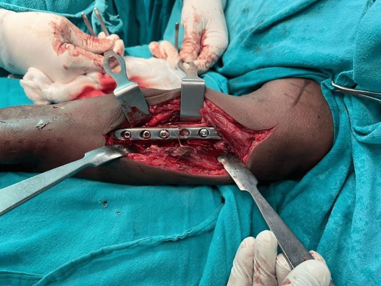
This clinical photograph captures an intraoperative view of an open reduction and internal fixation (ORIF) of a humeral fracture. The surgical site is prepared with blue sterile drapes and accessed via an anterolateral Henry’s approach. Several metallic surgical retractors (including Hohmann-style and right-angle retractors) are positioned to maintain visualization of the surgical field by retracting the biceps and brachialis muscles. A stainless steel orthopedic locking compression plate (LCP) or limited contact dynamic compression plate (LC-DCP) is shown positioned over the anterolateral surface of the humerus. Several screw holes are visible in the plate, with some already occupied by cortical or locking screws to stabilize the bone fragments. The image demonstrates the critical steps of alignment and hardware placement in orthopedic trauma surgery. Visible landmarks include the flexed elbow with skin markings and the deep exposure of the humeral shaft, emphasizing the relationship between the implant and the underlying musculoskeletal anatomy.
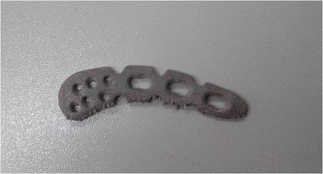
A clinical photograph of an orthopedic surgical implant: a Locking Compression Plate (LCP) designed for the superior anterior clavicle, manufactured using Electron Beam Melting (EBM) 3D printing technology from Ti-6Al-4V titanium alloy. The plate exhibits a contoured, elongated, and slightly curved morphology to match the anatomical shape of the clavicle. The proximal end (left) features a widened head with multiple small, circular locking screw holes. The distal shaft (right) contains three larger, oval-shaped dynamic compression apertures. The surface texture is notably granular and matte, characteristic of the additive manufacturing process, with visible rough edges and surface irregularities likely due to partially melted powder particles. This specimen demonstrates the application of patient-specific additive manufacturing in orthopedic trauma surgery to enhance implant strength and fit compared to traditional forged or cast plates.
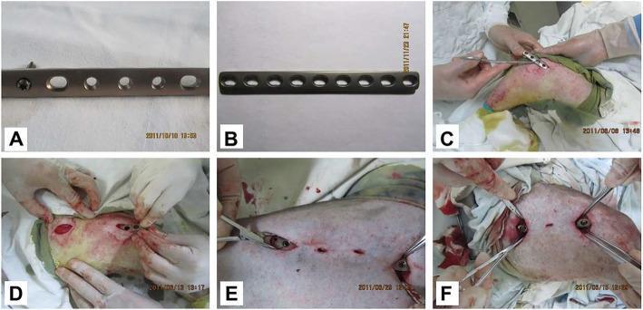
A series of clinical photographs and hardware images demonstrating orthopedic internal fixation. Panels (A) and (B) show the structural design of two 9-hole orthopedic plates: a Locking Compression Plate (LCP) with combination holes allowing for both locking and compression screws, and a Limited Contact Dynamic Compression Plate (LC-DCP) with uniform oblong holes designed to reduce bone-to-plate contact and protect periosteal blood supply. Panels (C) through (F) depict the surgical application of these plates on a femur using the Minimally Invasive Percutaneous Plate Osteosynthesis (MIPPO) technique. The images show small skin incisions, the insertion of the plates along the bone shaft using surgical forceps, and the subsequent fixation with screws through these limited portals. This visual material illustrates the comparative surgical approach and hardware characteristics used in veterinary orthopedic surgery, specifically focusing on femoral fracture management and the biological advantages of minimally invasive plate osteosynthesis over traditional open reduction.
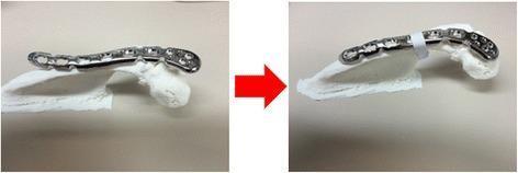
This comparison photograph illustrates the pre-operative planning and contouring of an orthopedic osteosynthesis plate using a patient-specific 3D-printed anatomical model. The images show a side-by-side 'before' and 'after' view of a metallic 3.5-mm locking compression plate (LCP) being adapted for acromial fixation. The plate features a series of Combi holes, designed for both angle-stable locking screws and dynamic compression cortical screws. In the left frame, the distal clavicle reconstruction plate is positioned relatively flat against the white 3D-printed model of the acromion. In the right frame, following manual contouring with plate benders, the plate exhibits a distinct anterior curvature. This adjustment is designed to lift the anterior acromion, correcting for down-sloping to prevent subacromial impingement on the rotator cuff. The use of 3D printing in this context demonstrates advanced surgical planning for complex orthopedic anatomy where standard pre-contoured plates are unavailable.
DCP and LCP in Fracture Fixation
Evolution: DCP → LC-DCP → LCP
| Generation | Full Name | Key Advance |
|---|---|---|
| DCP | Dynamic Compression Plate | First standardised AO compression plate |
| LC-DCP | Limited Contact - DCP | Undercut design to reduce periosteal contact |
| LCP | Locking Compression Plate | Combination hole allowing both locking and compression screws |
1. DCP - Dynamic Compression Plate
Design
- Oval/sloped screw holes with an inclined, spherical surface inside
- When a cortical screw is tightened, the rounded screw head rides down the slope of the hole, translating the bone toward the fracture - this generates axial compression across the fracture site
- Each screw can generate up to 2-3 mm of compression
Mechanism of Stability
- Friction-dependent - stability relies entirely on compression of the bone against the undersurface of the plate
- The screw holds the plate against bone; the frictional force between plate and bone/periosteum is what resists shear and torsion
- If friction is lost (screw under-tightened, bone resorption, osteoporosis), the construct fails rapidly
- Failure mode: screws loosen sequentially (one by one)
Biomechanics
- Requires anatomical reduction and direct bone-to-bone contact - the bone participates in load-sharing
- When properly applied with compression, the bone cortices resist bending loads and frictional contact resists torsion
- A gap on the cortex opposite the plate creates a fulcrum causing rapid plate bending failure
Problems with DCP
- Large flat undersurface = maximum periosteal contact = disrupts periosteal blood supply
- Stress shielding due to rigidity
- Fails early in osteoporotic bone (poor purchase)
- This led to development of the LC-DCP (undercut undersurface reduces contact by ~50%, protecting periosteum and cortical blood supply)
2. LCP - Locking Compression Plate
Design
- Features a combination hole (combi-hole): one half is the DCP oval compression slot; the other half has threaded walls that accept a locking screw
- Locking screw has a threaded head that engages threads in the plate hole, creating a fixed-angle, rigid screw-plate interface
- Can use conventional screws, locking screws, or both in the same plate
Mechanism of Stability
- Internal fixator principle - locking screws create a fixed-angle device; stability is independent of bone-plate contact
- No compression needed between plate and bone; plate can even be held off the bone (bridging)
- Because each screw is locked at a fixed angle to the plate, the entire construct behaves as a single unit - a plate-screw frame
Biomechanics: Locking vs Conventional Construct Failure
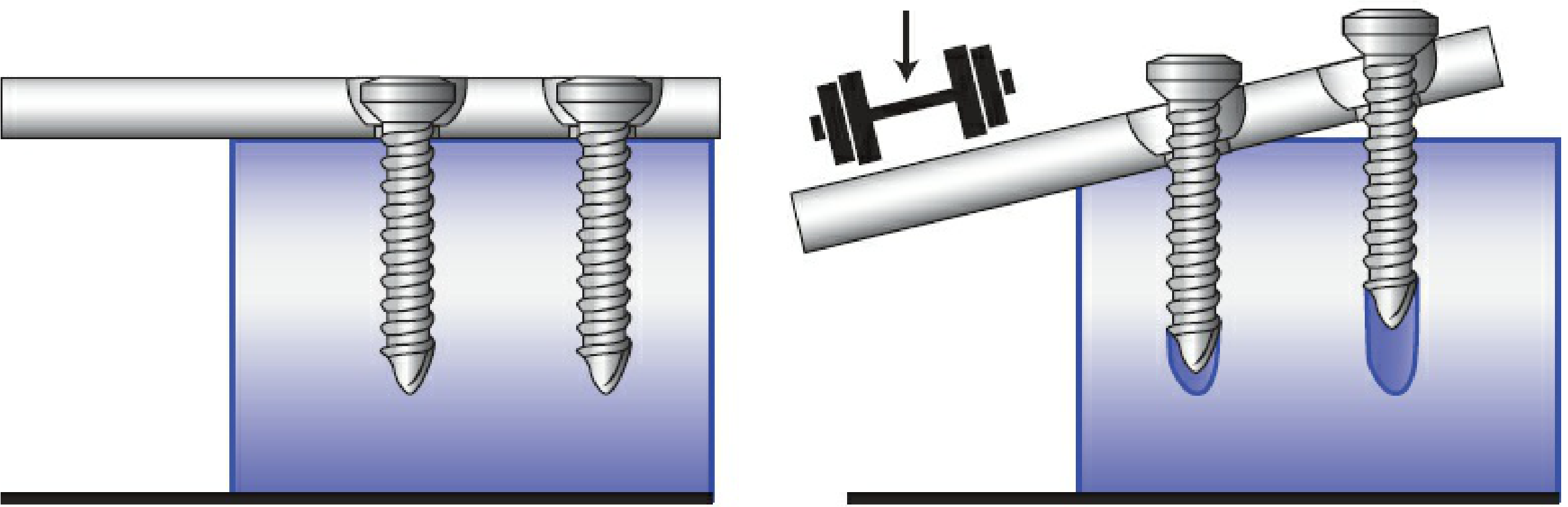
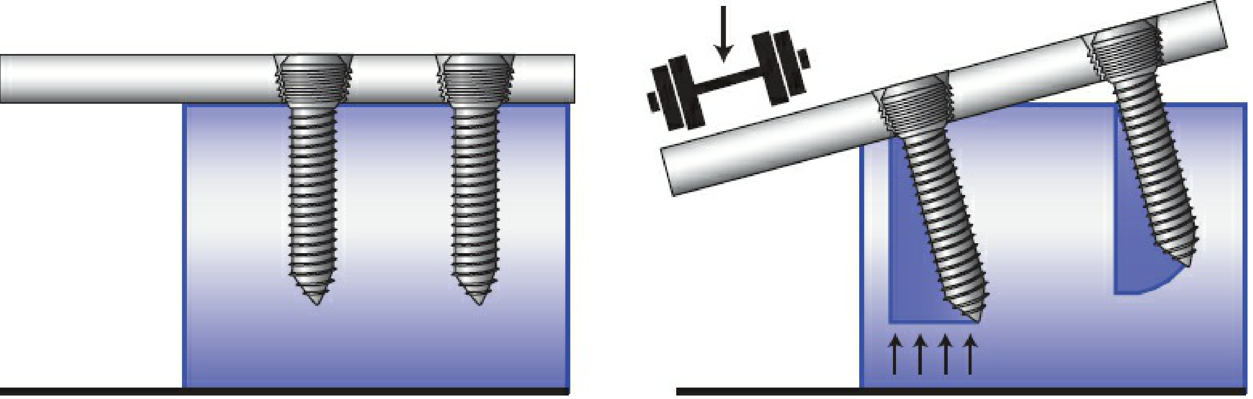
- Screws lose bony purchase sequentially
- One loose screw compromises the whole construct
- Fails by screw pull-out (individual)
- Creates multiple fixed-angle devices
- All screws must fail simultaneously
- Bone fails in compression before screws individually pull out
- Far superior in osteoporotic bone
Head-to-Head Comparison
| Feature | DCP | LCP |
|---|---|---|
| Screw type | Conventional cortical/cancellous | Threaded-head locking screw (+ optional conventional) |
| Screw-plate interface | Spherical (slides/compresses) | Threaded (fixed angle, locked) |
| Stability mechanism | Friction between plate and bone | Fixed-angle internal fixator; bone-plate contact not needed |
| Bone contact | High (flat undersurface) | Reduced/minimal (can bridge) |
| Periosteal blood supply | Compromised by plate pressure | Preserved (plate elevated off bone) |
| Requires anatomic reduction | Yes (for compression and load-sharing) | No (can be used as bridge plate) |
| Osteoporotic bone | Poor (screws pull out) | Excellent (all screws fail simultaneously) |
| Generates compression | Yes (dynamic compression via hole slope) | Via DCP half of combi-hole only |
| Failure mode | Sequential screw loosening | Simultaneous failure after bone compression failure |
| Working length effect | Stiffer with more screws across fracture | Increasing working length reduces stiffness, promotes callus |
| Use as bridge plate | Not ideal | Ideal (MIPPO technique) |
| Best indication | Simple transverse/oblique diaphyseal fractures with good bone quality | Osteoporotic bone, periarticular fractures, comminuted fractures, MIPPO |
Key Clinical Concepts
Working Length
- The distance between the innermost screws on either side of the fracture
- Increasing working length (leaving empty holes near fracture) reduces construct stiffness - distributes motion across more fragments, promotes callus formation (secondary bone healing)
- Screws closest and furthest to the fracture contribute most to stiffness; each additional intermediate screw adds progressively less
Screw Insertion Accuracy (LCP)
- Locking screws must be inserted precisely perpendicular (or at design angle) to the plate
- Even 5° deviation reduces bending stability to 63%; 10° reduces it to 31%
- Incomplete thread engagement = loss of mechanical stability
Plate Hole Over Fracture
- Placing an empty screw hole directly over the fracture greatly increases risk of plate fatigue fracture (stress concentration at the hole)
Variable Angle Locking
- Newer LCP designs allow variable-angle locking trajectories
- Less mechanically stable than fixed-axis locking; clinical effectiveness remains unproven
Indications Summary
- Simple fracture patterns (transverse, short oblique)
- Good bone quality
- When inter-fragmentary compression is needed (e.g., lag screw + neutralisation plate)
- Diaphyseal fractures (radius, ulna, forearm, clavicle)
- Osteoporotic bone
- Periarticular and metaphyseal fractures (distal femur, proximal humerus, distal tibia)
- Comminuted/multi-fragmentary fractures
- Bridge plating (MIPPO - minimally invasive percutaneous plate osteosynthesis)
- Periprosthetic fractures
- When preserving periosteal blood supply is a priority
Blood supply of long bones
Blood Supply of Long Bones
Diagrams
The Three Systems
1. Nutrient Artery System (Diaphyseal Supply)
- High-pressure system - dominant supply to the diaphysis
- Supplies ~60% of cortical bone vascularization
- A named systemic artery branch enters the diaphyseal cortex via the nutrient foramen and canal
- Inside the medullary cavity it bifurcates into ascending and descending medullary trunks toward each metaphysis
- Further branches into arterioles in the endosteal cortex → supplies inner 2/3 of the mature diaphyseal cortex via the Haversian system
The nutrient foramina develop as the pathways of the principal vessels of periosteal buds during ossification.
2. Metaphyseal-Epiphyseal System
- Arises from the periarticular vascular plexus (e.g., geniculate arteries around the knee)
- Epiphyseal arteries - enter through separate foramina and supply the epiphyseal cancellous bone and articular end
- Metaphyseal arteries - arise from periosteal vessels incorporated into the metaphysis as the bone widens during growth
- The two systems are separated by the physis in children - the growth plate is avascular and relies on diffusion from vessels on both sides
3. Periosteal System
- Low-pressure system - supplies the outer 1/3 of the mature diaphyseal cortex
- Consists mostly of capillaries running in the periosteum
- Enter cortex via Volkmann's canals (transverse) → connect to longitudinal Haversian canals
- Also fed by muscular branches and tendon insertion vessels
- Provides collateral supply when the nutrient artery is disrupted (fracture, intramedullary reaming)
Direction of Blood Flow
| Condition | Arterial direction | Venous direction |
|---|---|---|
| Normal mature bone | Centrifugal (medulla → cortex → periosteum) | Centripetal (outside → inside) |
| Fracture / immature bone | Centripetal (periosteum → cortex) | - |
- In intact bone, the high-pressure nutrient system dominates → flow is centrifugal
- When the nutrient artery is disrupted or in immature bone, periosteal system pressure dominates → flow reverses to centripetal
- This is why periosteum must be preserved during fracture surgery
Regulation of Bone Blood Flow
- Influenced by metabolic, humoral, and autonomic inputs
- Hypoxia, hypercapnia, and sympathectomy all increase bone blood flow
- Vessels have vasoactive receptors: β-adrenergic, muscarinic, thromboxane/prostaglandin
- Bone blood flow is the major determinant of fracture healing
Bones with Tenuous Blood Supply
| Bone | Vulnerable fracture |
|---|---|
| Scaphoid | Waist fractures → proximal pole AVN |
| Femoral head | Neck-of-femur fractures (retinacular vessels disrupted) |
| Talus | Neck fractures |
| Odontoid process | Base fractures |
Microanatomy
- Volkmann's canals run transversely/obliquely through cortical bone - link periosteal vessels to Haversian canals
- Haversian canals run longitudinally - each contains a single arteriole + venule or capillary
- Bone lacks lymphatic vessels - lymphatic drainage occurs only from the periosteum
Extensor mechanism of knee
extensor mechanism knee quadriceps patella patellar tendon tibial tuberosity anatomy diagram
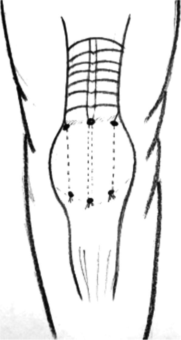
Anatomical Diagram of the Knee Extensor Mechanism. This schematic illustration depicts a surgical approach for repairing the patellar tendon or quadriceps tendon, particularly in the context of chronic ruptures. The diagram features a central circular patella situated between the proximal quadriceps muscle and the distal tibia/fibula. Surgical markings are indicated by six black dots: three positioned at the superior pole of the patella and three at the inferior pole. These dots are connected by three longitudinal dashed lines—one central and two paracentral—representing transosseous tunnels or suture pathways designed to secure the tendon to the bone. Proximal to the patella, a series of horizontal lines represents the quadriceps muscle, potentially indicating a V-Y advancement or lengthening procedure (Codivilla technique). The illustration serves as an educational guide for orthopedic surgical planning in patients with complex extensor mechanism injuries, such as those associated with systemic comorbidities like tertiary hyperparathyroidism.
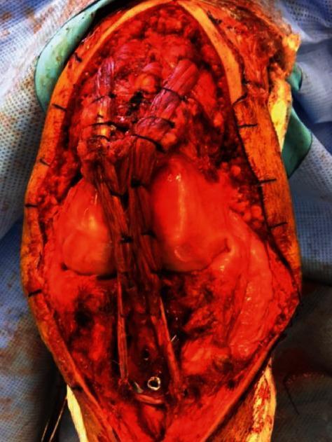
This intraoperative clinical photograph displays an open surgical reconstruction of the extensor mechanism of the knee. The surgical field reveals the anterior aspect of the knee with the patella centrally located. The image captures the 'framing' technique using a semitendinosus tendon autograft or allograft. Two distinct tendon strands are visible, having been passed through the vastus medialis and vastus lateralis muscles superiorly. These strands are then brought down and sutured to each other and around the prepatellar rim to reinforce the patellar tendon reconstruction. Interrupted sutures are visible along the graft strands, securing them to the underlying quadriceps and patellar structures. The distal portion of the graft is seen extending toward the tibial tuberosity. This procedure is typically indicated for chronic patellar tendon ruptures or cases with poor tissue quality, aiming to restore active knee extension and stable patellar tracking.
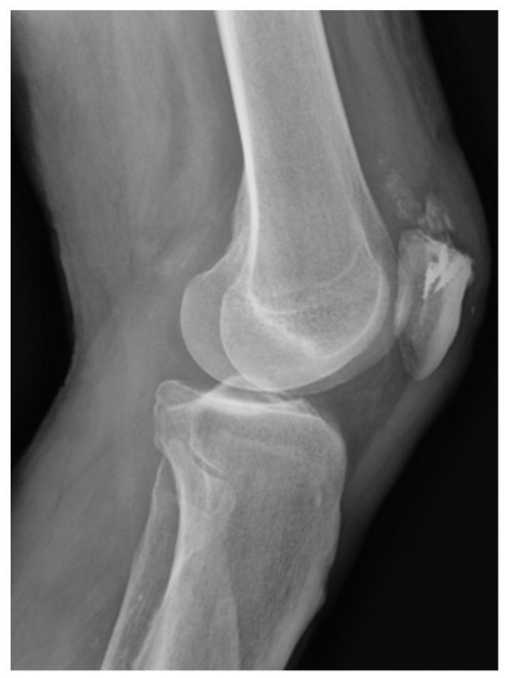
This lateral view X-ray of the knee demonstrates the anatomical alignment of the distal femur, proximal tibia, and patella. The primary clinical focus is on the patellofemoral compartment, where evidence of prior orthopedic surgical intervention for quadriceps tendon reconstruction is visible. Four radiopaque suture anchors (TWINFIX) are identifiable as dense, metallic-density markers embedded within the superior aspect of the patellar bone. Faint, linear radiopacities extending from these anchors represent high-strength non-absorbable suture material used to secure the quadriceps tendon. The joint space between the femoral condyles and the tibial plateau appears preserved, and the tibial tuberosity is clearly visible on the anterior proximal tibia. This image serves as a clinical example of postoperative hardware placement for extensor mechanism repair in the knee, highlighting the use of suture anchors for soft-tissue-to-bone fixation.
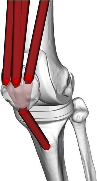
This musculoskeletal model illustrates the biomechanics of the knee joint, specifically focusing on the extensor mechanism. The anatomical diagram features a schematic 3D rendering of the distal femur, proximal tibia, fibula, and patella. Red cylindrical vectors represent the Hill-type musculotendon units of the quadriceps femoris. These muscle representations originate superiorly and converge to insert onto the superior aspect of the patella. A single red vector extends from the inferior pole of the patella to the tibial tuberosity, representing the patellar ligament. The model demonstrates the patella's role as a fulcrum or frictionless pulley, transmitting forces from the quadriceps to the tibia to facilitate knee extension. A prosthetic spacer or tibial component is visible between the femoral condyles and the tibial plateau, suggesting the model is configured for post-operative orthopedic analysis or total knee arthroplasty (TKA) simulation. This visualization is used in biomechanical engineering to estimate joint contact forces and limb dynamics.
quadriceps femoris four heads rectus femoris vastus medialis lateralis intermedius anatomy knee
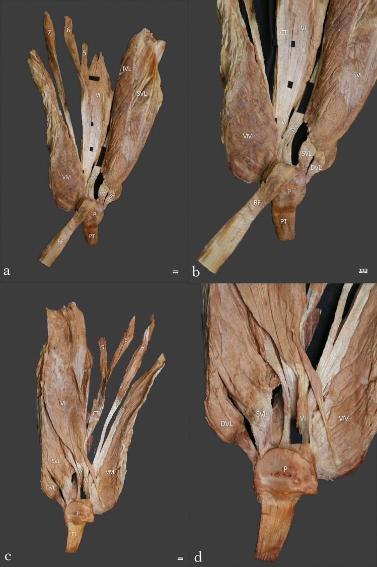
This set of clinical photographs shows a detailed anatomical dissection of a Type IV quadriceps femoris complex from a left-sided human specimen. Four views are provided: wide anterior (a), enlarged anterior (b), wide posterior (c), and enlarged posterior (d). The images demonstrate the multi-layered and multi-headed structure of the quadriceps tendon. Key anatomical structures labeled include the rectus femoris (RF), vastus medialis (VM), and three distinct parts of the vastus lateralis: superficial (SVL), intermediate (IVL), and deep (DVL). The vastus intermedius (VI) is shown in the central deep layer. Notably, the specimen illustrates accessory heads numbered 5, 6, and 7, highlighting the morphological variability of the muscle. A common tendon (CT) serves as a fusion point for the fifth and sixth heads. The distal attachment site includes the patella (P) and patellar tendon (PT). This educational visual is intended for advanced musculoskeletal anatomy and surgical planning, illustrating the complex stratification and tendinous architecture of the knee extensors.
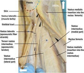
This clinical photograph displays a macro-dissection of the distal human extensor apparatus of the knee, highlighting the complex multi-layered architecture of the quadriceps muscle group. The image identifies the muscle bellies and aponeurotic insertions of the vastus lateralis, vastus medialis, rectus femoris, and vastus intermedius. Notably, it demonstrates the tensor vastus intermedius and its aponeurotic tendon, characterizing the five-component model of the quadriceps. The rectus femoris is medially reflected to reveal the insertion of the vastus medialis into both the rectus femoris and the vastus intermedius. The vastus lateralis shows distinct aponeurotic fiber strands and a strong muscle belly inserting at the supero-lateral semi-circle of the patella (indicated by a red dotted line). In contrast, the vastus medialis occupies the supero-medial half of the patella's upper semi-circle (indicated by a blue dotted line). Fiber orientations for the lateral components are directed toward the medial femoral condyle, illustrating the dynamic balance required for patellar tracking and knee extension stability.
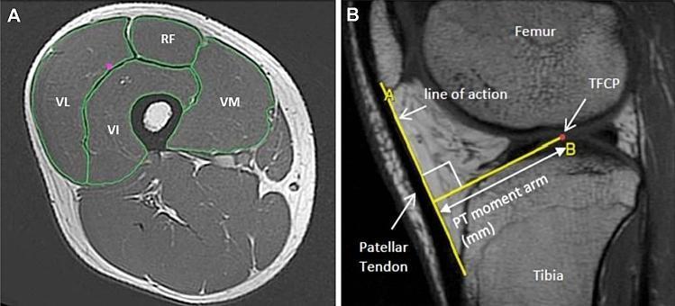
This composite educational material consists of two T1-weighted magnetic resonance (MR) images demonstrating musculoskeletal anatomy and biomechanical measurements of the lower limb. Image A is an axial MR cross-section of the mid-thigh, featuring manually segmented green outlines of the four quadriceps femoris muscles: the Rectus Femoris (RF) located anteriorly, the Vastus Lateralis (VL) laterally, the Vastus Medialis (VM) medially, and the Vastus Intermedius (VI) situated centrally and deep, surrounding the femur. This view is utilized for calculating anatomical cross-sectional area (ACSA) and muscle volume. Image B is a sagittal MR image of the knee joint illustrating the biomechanical concept of the patellar tendon moment arm (PTMA). The PTMA is visually defined as the perpendicular distance (white line) between the patellar tendon's line of action (yellow line A) and the tibiofemoral contact point (TFCP, marked by a red dot at point B). This measurement is critical for assessing the mechanical advantage of the quadriceps during knee extension. Both images serve as primary diagnostic and research tools in sports medicine and orthopedics for evaluating muscle architecture and joint mechanics.
Extensor Mechanism of the Knee
Components (Proximal to Distal)
1. Quadriceps Femoris Muscle (Four Heads)
| Head | Origin | Special Features |
|---|---|---|
| Rectus femoris | Anterior inferior iliac spine (AIIS) + groove above acetabulum | Only bi-articular head - also flexes the hip; lies superficially in the center |
| Vastus lateralis | Greater trochanter + lateral lip of linea aspera | Largest head; pulls patella laterally |
| Vastus medialis | Medial lip of linea aspera + intertrochanteric line | Distal fibres (VMO) pull patella medially; key for patellar tracking |
| Vastus intermedius | Anterior and lateral femoral shaft | Lies deepest, directly under rectus femoris |
2. Quadriceps Tendon
- A trilaminar structure formed by the convergence of all four heads:
- Superficial layer - rectus femoris
- Middle layer - vastus medialis and vastus lateralis
- Deep layer - vastus intermedius
- Inserts into the superior pole of the patella
- Some fibres of rectus femoris pass over the anterior surface of the patella and continue directly into the patellar tendon ("quadriceps expansion")
3. Patella
- The largest sesamoid bone in the body, embedded within the quadriceps tendon
- Ossifies from a single centre at age 3-5 years (bipartite patella is a normal variant ~2%)
- Functions:
- Acts as a mechanical pulcrum/pulley - increases the lever arm of the quadriceps force by approximately 50%, greatly improving mechanical efficiency of extension
- Protects the anterior knee joint (articular cartilage)
- Distributes compressive forces across the trochlear groove
4. Medial and Lateral Retinacula
- Expansions of the vastus medialis and lateralis that pass on either side of the patella and attach to the tibial condyles
- Medial retinaculum - primary soft-tissue restraint to lateral patellar dislocation; contains the Medial Patellofemoral Ligament (MPFL) (strongest static medial restraint, provides ~60% of medial restraining force)
- Lateral retinaculum - can become tight causing lateral patellar tilt; divided in lateral release procedures
- These allow limited extension even after complete quadriceps or patellar tendon rupture (partial extension lag only)
5. Patellar Tendon (Patellar Ligament)
- Runs from the inferior pole of the patella to the tibial tuberosity
- Technically a ligament (bone to bone), but functionally the continuation of the quadriceps tendon
- Average length ~5 cm; width ~3 cm
- Normal Insall-Salvati ratio = patellar tendon length ÷ patella length = 1.0 (±0.2)
- Ratio >1.2 = patella alta (high-riding patella - predisposes to instability)
- Ratio <0.8 = patella baja (low-riding - poor quadriceps mechanics, after TKR)
6. Tibial Tuberosity
- Bony attachment on the anterior proximal tibia
- Apophysis in children - subject to Osgood-Schlatter disease (traction apophysitis)
- Used as the distal landmark for tibial tubercle osteotomy (TTO) procedures to correct patellar maltracking
Q-Angle (Quadriceps Angle)
- Line from ASIS → centre of patella (direction of quadriceps pull)
- Line from centre of patella → tibial tuberosity (direction of patellar tendon pull)
| Normal value | Significance | |
|---|---|---|
| Males | ~10-12° | - |
| Females | ~15-18° | Wider pelvis creates greater valgus vector |
| Abnormal | >20° | Increased lateral patellar stress → instability risk |
Vastus Medialis Oblique (VMO)
- The most distal fibres of vastus medialis run at 50-55° to the quadriceps tendon axis (versus 15-18° for the proximal VM fibres)
- Inserts into the medial patella and medial retinaculum
- Provides a medially directed force on the patella throughout the range of motion
- The last 10-15° of extension ("terminal extension") particularly depends on VMO activity
- VMO wasting/weakness is the most common cause of patellar maltracking and anterior knee pain - targeted VMO strengthening is the cornerstone of physiotherapy
Disruption of the Extensor Mechanism
| Level | Injury | Age group |
|---|---|---|
| Quadriceps tendon | Quadriceps tendon rupture | >40 years; systemic disease (SLE, DM, gout, hyperparathyroidism, uraemia, steroids, fluoroquinolones) |
| Patella | Patellar fracture (most common cause) | Any age; direct blow |
| Patellar tendon | Patellar tendon rupture | <40 years, athletes; avulsion from inferior pole |
| Tibial tuberosity | Avulsion fracture | Adolescents (apophysis unfused) |
Nerve Supply
- All four heads of quadriceps femoris are innervated by the femoral nerve (L2, L3, L4)
- This is why femoral nerve palsy causes profound quadriceps weakness and inability to extend the knee against gravity
Blood Supply
- Lateral superior and inferior geniculate arteries (from popliteal artery)
- Medial superior and inferior geniculate arteries
- Descending genicular artery (from femoral artery)
- These form a peripatellar anastomotic ring - enters the patella predominantly through the anterior mid-portion and inferior pole; the superior pole is relatively avascular (important in fractures)

Diagnosis
posterior hip dislocation posterior wall acetabular fracture CT scan 3D reconstruction
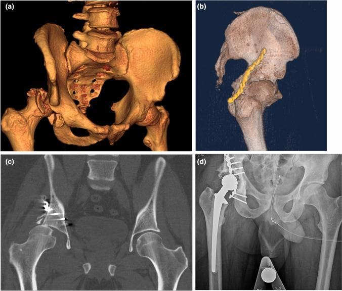
A multi-panel clinical imaging series documenting the progression and surgical management of a complex hip injury. (a) 3D reconstructed CT scan of the pelvis showing a comminuted posterior wall acetabular fracture with associated posterior hip dislocation. (b) 3D CT reconstruction demonstrating postoperative internal fixation using a curved metallic plate and screws along the posterior acetabular rim. (c) Coronal 2D CT slice showing osteosynthesis failure, characterized by hardware displacement, loss of reduction, and superior subluxation of the femoral head. (d) Anteroposterior (AP) pelvic radiograph following salvage surgery, illustrating a cemented total hip arthroplasty (THA). The radiopacity of the prosthetic femoral stem, acetabular cup, and cerclage wiring is clearly visible. The series illustrates the clinical transition from primary Open Reduction Internal Fixation (ORIF) failure to secondary arthroplasty in orthopaedic trauma management.
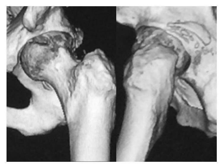
This diagnostic image consists of two 3D-reconstructed CT scan views of a left hip joint following a manual reduction procedure. The imaging depicts the anatomical relationship between the proximal femur and the pelvis. Key findings include a fracture of the posterior wall of the acetabulum with a visible bone fragment. Furthermore, an impaction injury or depression is present on the posterior-superior aspect of the femoral head, characteristic of damage sustained during a posterior hip dislocation. The reconstruction allows for assessment of joint congruity and the integrity of the acetabular rim. The clinical significance of these findings relates to orthopedic stability, where the combination of a posterior wall defect and femoral head impaction (analogous to a Hill-Sachs lesion in the shoulder) increases the risk of recurrent dislocation. This material is suitable for orthopedic surgical planning and educational review of traumatic hip injuries.
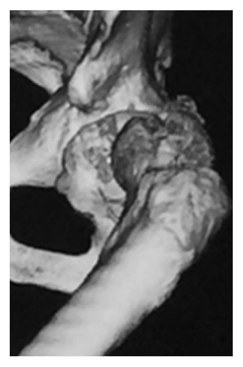
This diagnostic image is a 3D reconstruction from a Computed Tomography (CT) scan focusing on the left hip joint. It demonstrates a posterior redislocation of the hip, characterized by the femoral head being completely displaced outside of its anatomical position within the acetabulum. Significant pathology is visible at the articulation site, specifically an impaction injury where the posterior margin of the acetabulum has created a distinct depression or 'indentation' in the posterior aspect of the femoral head. There is also evidence of cortical irregularity and fragmentation at the posterior acetabular wall, consistent with a posterior wall fracture. The proximal femur and pelvic structures (ilium and ischium) are clearly visualized, illustrating the severe loss of joint congruity. This image serves as a clinical example of traumatic hip instability and the associated bony complications, such as impaction fractures, that can occur during recurrent dislocation events in orthopedic surgery and trauma medicine.
Diagnosis: Left Posterior Hip Fracture-Dislocation with Posterior Wall Acetabular Fracture
Imaging Summary
Key CT Findings
Left Hip (Abnormal)
- Complete posterior and superior dislocation of the left femoral head - the head is displaced posterosuperiorly out of the acetabulum, clearly visible on coronal reformats and 3D reconstructions
- Posterior wall acetabular fracture - fracture of the posterior rim of the left acetabulum (the classic associated injury)
- Intra-articular bony fragments - small loose fragments within and around the acetabular fossa, sheared off by the dislocating femoral head
- Femoral head and neck appear grossly intact without a femoral neck fracture - an important distinction
Right Hip (Normal)
- Right femoral head is congruent within the acetabulum
- No fracture, subluxation, or dislocation
Pelvis
- Pelvic ring intact - no sacral, iliac wing, or pubic ramus fractures
- Sacroiliac joints and pubic symphysis normal
Classification
| Type | Description |
|---|---|
| I | Dislocation with or without minor fracture |
| II | Dislocation with single large posterior wall fragment |
| III | Dislocation with comminuted posterior wall fragment |
| IV | Dislocation with fracture of acetabular floor |
| V | Dislocation with fracture of femoral head (Pipkin) |
Mechanism of Injury
Clinical Presentation (Expected)
- Left leg held in flexion, adduction, and internal rotation (pathognomonic)
- Leg appears shortened
- Greater trochanter and buttock unusually prominent
- Severe pain, inability to move the hip
Neurovascular Assessment - Critical
- Sciatic nerve injury in ~10% of posterior dislocations - most commonly the peroneal division
- Test: weakness of dorsiflexion (foot drop), extensor hallucis longus, numbness over dorsum of foot
- Femoral vessels generally not at risk in posterior dislocation (unlike anterior)
Radiographic Clues (on plain film - before CT)
| Sign | Posterior Dislocation |
|---|---|
| Lesser trochanter | Not visible on AP (superimposed on shaft - internal rotation) |
| Femoral head size | Appears smaller than contralateral (closer to cassette) |
| Shenton's line | Disrupted |
| Hip position | Flexed, adducted, internally rotated |
Management
1. Emergency - Closed Reduction (Orthopaedic Emergency)
- Must be performed within 6 hours to minimize risk of avascular necrosis (AVN)
- Performed under IV sedation or general anaesthesia
- Stimson technique (prone): hip and knee at 90°, downward pressure on proximal tibia
- Allis technique (supine): assistant stabilises pelvis; flex hip and knee to 90°, apply axial traction with gentle internal/external rotation
- Bigelow technique (supine): traction + circumduction
2. Post-Reduction
- Check neurovascular status again
- Post-reduction CT scan to:
- Confirm concentric reduction
- Identify residual intra-articular fragments
- Fully characterise the posterior wall fracture size
3. Surgical Indications (ORIF via Kocher-Langenbeck approach)
- Posterior wall fragment >40-50% of the acetabulum (joint instability)
- Intra-articular loose bodies preventing concentric reduction
- Femoral head fracture requiring fixation (Pipkin classification)
- Irreducible dislocation
4. Complications to Monitor
| Complication | Timing | Notes |
|---|---|---|
| Avascular necrosis (AVN) | Months-years | Up to 15% of all hip dislocations; risk increases with time to reduction |
| Post-traumatic arthritis | Years | Related to cartilage damage |
| Sciatic nerve palsy | Immediate | Peroneal division most common |
| Recurrent instability | Post-reduction | If >50% posterior wall involvement |
| Heterotopic ossification | Weeks-months | After ORIF |
Reference Images