
10 mark answer on treatment planning for orthognathic surgery from reyneke
Treatment Planning for Orthognathic Surgery (Reyneke)
Introduction
1. Patient Assessment and Problem Identification
Clinical Examination
- Facial thirds analysis: The face is divided into upper (trichion to glabella), middle (glabella to subnasale), and lower (subnasale to menton) thirds. Vertical and transverse symmetry of each third is assessed.
- Facial profile: The antero-posterior relationship of the maxilla and mandible is evaluated from the lateral view - assessing convexity or concavity of the profile.
- Lip posture and competence: Amount of upper incisor display at rest and on smiling; lip strain or incompetence at closure.
- Chin position: Evaluated in both AP and vertical dimensions.
- Nasolabial angle and nose: Affected by maxillary position and any planned Le Fort I movement.
Dental Occlusal Assessment
- Molar and canine Angle classification (Class I, II, III).
- Overjet and overbite - magnitude and direction.
- Transverse discrepancy - dental midlines, crossbites, arch width.
- Curve of Spee - depth requiring leveling.
- Dental compensations (dentoalveolar compensation that must be decompensated orthodontically before surgery).
2. Cephalometric Analysis (The Foundation of Reyneke's Planning)
Skeletal Parameters
| Measurement | Norm | Significance |
|---|---|---|
| SNA | 82° ± 2° | Maxillary AP position relative to cranial base |
| SNB | 80° ± 2° | Mandibular AP position |
| ANB | 2° ± 2° | Sagittal jaw relationship |
| Wits appraisal | 0 mm (F), -1 mm (M) | Functional occlusal plane-based jaw relationship |
| Facial axis angle (Ba-N to Pt-Gn) | 90° | Direction of condylar growth |
| Lower anterior facial height (LAFH) | ~55% of total | Vertical proportion |
| Gonial angle | 130° ± 7° | Mandibular morphology |
| Palatal plane angle (ANS-PNS to SN) | 8° ± 3° | Maxillary inclination |
Dentoalveolar Parameters
- Upper incisor to NA (angle and mm) - normal 22°, 4 mm
- Lower incisor to NB (angle and mm) - normal 25°, 4 mm
- IMPA (lower incisor to mandibular plane) - normal 90° ± 5°
- Interincisal angle - normal 130° ± 10°
Soft Tissue Parameters
- Nasolabial angle: 90-110°
- E-line (Ricketts): upper lip 4 mm, lower lip 2 mm behind the line
- H-angle (Holdaway): 7-15°
- Upper lip-to-incisor relationship at rest: 1-4 mm of incisor show
3. The Diagnostic Setup (Mock Surgery on Models)
Dental Study Models
Model Surgery Protocol (Reyneke's Sequence)
- Maxilla first: In most cases, the maxilla is repositioned first on the articulator because it is the reference jaw. The desired final maxillary position is established based on cephalometric and clinical data.
- Mandible second: The mandible is then autorotated to its new position once the maxilla is set, and any residual discrepancy is addressed by the mandibular osteotomy.
- Wafer construction: An intermediate wafer (interocclusal splint) is constructed at the intermediate occlusion (after maxillary repositioning, before mandibular movement), and a final wafer is constructed at the planned final occlusion.
4. Virtual Surgical Planning (VSP)
- Three-dimensional simulation of bony movements.
- Prediction of soft tissue changes.
- Fabrication of CAD/CAM-printed surgical splints and cutting guides.
- Superior accuracy compared to traditional 2D planning in complex cases.
5. Determining the Surgical Movements
Principles of Movement
- Sagittal (AP): Advancement or setback
- Vertical: Impaction or downgraft
- Transverse: Midline correction, asymmetry correction
Vertical Control
- Maxillary impaction causes autorotation of the mandible anteriorly and superiorly, reducing an increased LAFH and potentially eliminating the need for mandibular surgery.
- Maxillary downgraft is generally avoided due to instability.
The "Autorotation Concept"
Bimaxillary Surgery
6. Pre-surgical Orthodontics
- Decompensates dental compensations (e.g., uprighting proclined lower incisors in Class III cases, or flared upper incisors in Class II cases).
- Aligns and levels each arch independently.
- Coordinates arch widths so that transverse discrepancies are accounted for.
- Establishes ideal arch form so that the planned interdigitation can be achieved at surgery.
7. Prediction Tracing and Soft Tissue Prediction
- Trace the current cephalogram on acetate.
- Physically cut and reposition the bony segments according to planned movements.
- Overlay soft tissue and estimate soft tissue changes using established ratios:
- Upper lip: follows maxillary anterior movement at approximately 50-70%
- Lower lip and chin: follows mandibular movement at approximately 60-100%
- Nasolabial angle: narrows with maxillary advancement; decreases with impaction.
8. Sequencing of Surgery
Standard Sequence
- Le Fort I osteotomy first (maxilla repositioned and fixed with intermediate wafer).
- BSSO second (mandible brought to planned final position using final wafer).
- Genioplasty last, if required, to refine chin position.
Why Maxilla First?
- The maxilla provides the stable reference around which mandibular position is established.
- The intermediate wafer records the post-maxillary/pre-mandibular occlusion, ensuring accurate mandibular repositioning.
9. Stability and Relapse Considerations
| Movement | Stability |
|---|---|
| Maxillary impaction | Most stable |
| Mandibular advancement | Stable (especially with rigid fixation) |
| Maxillary advancement | Stable |
| Maxillary expansion (SARPE) | Moderate |
| Mandibular setback | Less stable (muscular relapse) |
| Maxillary downgraft | Least stable |
10. Multidisciplinary Team
- Oral and maxillofacial surgeon - surgical planning and execution
- Orthodontist - pre- and post-surgical orthodontics
- Prosthodontist - if restorative work is part of the plan
- Speech therapist - in cases with significant mandibular advancement or cleft-related issues
- Psychologist - patient expectations and body image counseling
Summary Flowchart (Reyneke's Protocol)
Clinical Examination
        ↓
Cephalometric Analysis
        ↓
Pre-surgical Records (photos, models, radiographs)
        ↓
Problem List + Objectives
        ↓
Pre-surgical Orthodontics (decompensation, alignment)
        ↓
Final Records + Model Surgery on Articulator
        ↓
Prediction Tracing / VSP
        ↓
Wafer Construction
        ↓
Surgery (Le Fort I → BSSO → Genioplasty)
        ↓
Post-surgical Orthodontics (detailing)
        ↓
Retention + Review
Key Reyneke Concepts to Remember
- Maxilla-first planning - the maxilla is the reference jaw.
- Autorotation - mandibular movement following maxillary repositioning must be planned.
- Decompensation before surgery is mandatory.
- Intermediate and final wafers guide intra-operative jaw positioning.
- Vertical dimension is the primary variable in planning.
- Stability hierarchy - impaction > advancement > setback > downgraft.
- Soft tissue prediction must confirm skeletal planning.
- Multidisciplinary approach is mandatory.
10 mark answer on treatment planning for orthognathic surgery from reyneke with diagrams
orthognathic surgery treatment planning cephalometric analysis
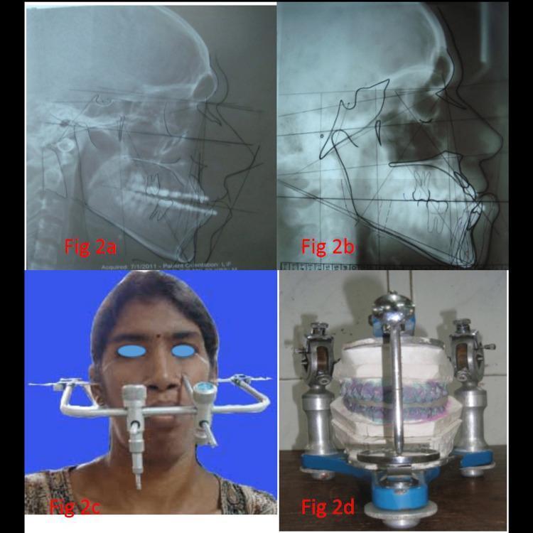
This four-panel composite image illustrates the preoperative planning and surgical simulation stages for orthognathic surgery. Panels (a) and (b) show lateral cephalometric radiographs utilized for cephalometric analysis. Panel (a) is a preoperative radiograph with initial tracings, while panel (b) displays a prediction tracing (VTO - Visualized Treatment Objective), superimposing planned skeletal and dental movements onto the baseline profile. Key landmarks and reference planes (such as the Frankfort horizontal and mandibular plane) are delineated to assess jaw relationship and dental compensation. Panel (c) is a clinical photograph showing the clinical application of a face-bow on a patient to record the spatial relationship of the maxillary arch to the temporomandibular joints. Panel (d) shows the subsequent laboratory phase, where dental casts are mounted on a semi-adjustable articulator for model surgery and the fabrication of a surgical splint. This sequence demonstrates the integrated workflow of diagnostic imaging, cephalometric prediction, and mechanical simulation essential for correcting dentofacial deformities.
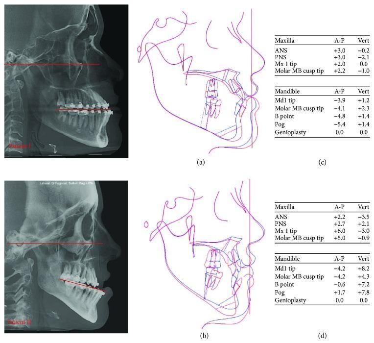
Educational visual regarding orthognathic surgery planning for Class III malocclusion, featuring lateral cephalometric analysis for two patients. The left column displays lateral radiographs (Patient I and II) with red lines highlighting the occlusal plane (OP) and Frankfort horizontal plane, demonstrating variations in OP inclination. The center column (a, b) provides superimpositions of original (blue) and predictive (red) cephalometric tracings, illustrating planned maxillomandibular complex (MMC) movements, including clockwise and counterclockwise rotations. The right column (c, d) contains quantitative data tables detailing anticipated anterior-posterior (A-P) and vertical (Vert) surgical changes for anatomical landmarks such as the ANS, PNS, B-point, and Pogonion. This comparison highlights how different facial morphotypes (brachycephalic vs. dolichocephalic) influence the surgical strategy to optimize facial harmony, chin projection, and the mandibular contour.
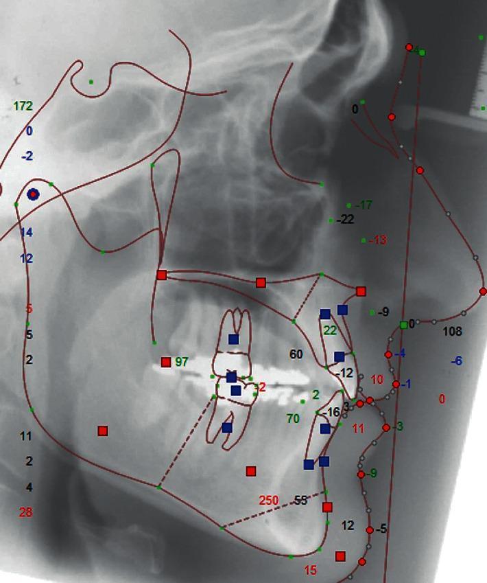
This diagnostic image shows a lateral cephalometric radiograph with a superimposed digital cephalometric tracing, commonly used in orthodontics and orthognathic surgery planning. The tracing utilizes red lines to delineate key anatomical contours, including the sella turcica, nasal bones, maxilla, mandible, and the soft tissue facial profile. Multi-colored markers (green dots, red squares, and blue squares) identify specific cephalometric landmarks such as Point A, Point B, Pogonion, Menton, and various dental positions. Numerical values in red, green, and blue text are dispersed throughout the tracing, representing angular and linear measurements essential for analyzing skeletal and dental relationships. Particular emphasis is placed on the maxillomandibular relationship and the dental occlusion, which are critical for assessing Class III malocclusion and orthodontic camouflage outcomes. The image illustrates the integration of radiographic imaging with quantitative analysis to evaluate facial profile aesthetics and treatment efficacy.
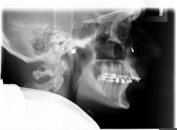
A lateral cephalometric radiograph of a human skull, primarily used in orthodontics and orthognathic surgery planning. Key visible anatomical structures include the cranium, maxilla, mandible, cervical vertebrae (C1-C2), and the nasal and orbital cavities. Radiopaque orthodontic appliances, including brackets and archwires, are visible on both the maxillary and mandibular teeth, indicating active dental treatment. Two distinct artificial metal markers are present on the patient's skin to assist in clinical localization: a square marker positioned near the individual hinge axis (pre-auricular area) and a triangular marker located over the right infraorbital rim. These markers serve as reference points for determining the axis-orbital plane (AOP). The soft tissue profile is clearly outlined, allowing for analysis of facial aesthetics in relation to underlying skeletal structures. This imaging is essential for calculating cephalometric angles and distances required for virtual surgical simulation and mounting in a digital articulator.
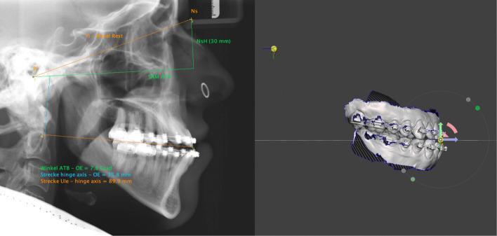
This composite image illustrates the integration of 2D cephalometric radiography with 3D digital dental modeling for orthodontic and orthognathic surgery planning. The left panel shows a lateral cephalometric X-ray with overlayed cephalometric analysis. Key reference points include the Nasal Rest (Ns), Axis Orbital Plane (AOP), and the articulator’s hinge axis. Quantitative measurements are displayed: an angle of 7.8 degrees between the upper occlusal plane (OE) and AOP, a 35.8mm vertical distance from the hinge axis to the OE, and an 89.9mm horizontal distance from the hinge axis projection to the upper incisor edge. The right panel displays a corresponding 3D intraoral scan of the dentition featuring active orthodontic appliances (brackets and wires). The model is oriented within a virtual world frame, featuring a transformation widget at the incisal edge for adjusting pitch, roll, and yaw. A red rotational arrow indicates planned movement. This combined approach facilitates virtual mounting and precise simulation of maxillofacial jaw repositioning.
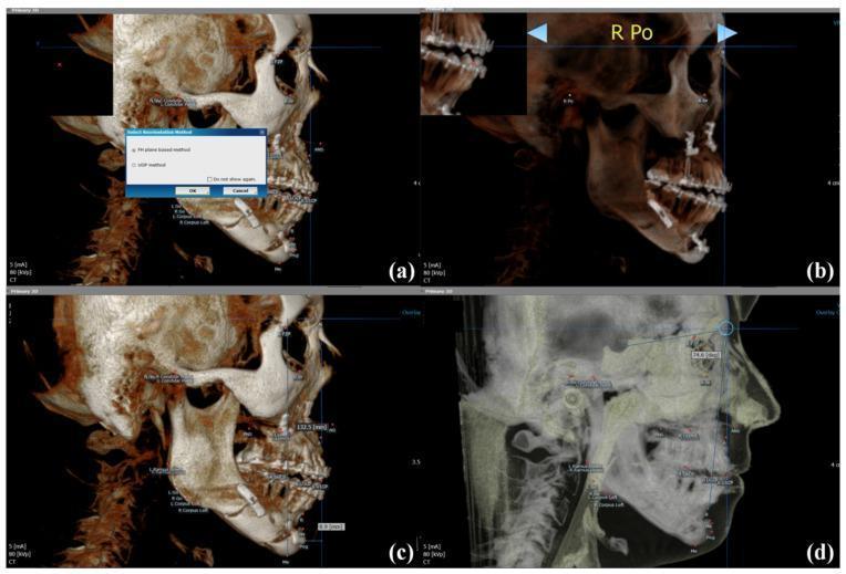
This composite diagnostic image demonstrates 3D cephalometric analysis using OnDemand 3D software for orthognathic surgery planning and skeletal stability assessment. Panel (a) shows the initial selection of the orientation method. Panel (b) illustrates 3D head orientation based on the Frankfort Horizontal (FH) plane, utilizing the right porion and bilateral orbitale as landmarks. Panel (c) displays linear measurements on a 3D skeletal volume rendered view, specifically measuring the distance from a Horizontal Reference Plane (HRP) to the menton (Me) and a Vertical Reference Plane (VRP) to the pogonion (Pog) to quantify mandibular position. Panel (d) shows an adjusted opacity view for angular measurement of the SNB angle (Sella-Nasion-B point), used to evaluate the anteroposterior relationship of the mandible to the cranial base. The images feature surgical hardware, including miniplates and screws, from a bilateral sagittal split ramus osteotomy (BSSRO). This toolset is essential for quantifying post-surgical skeletal changes and long-term stability in maxillofacial surgery.
Le Fort I osteotomy BSSO bimaxillary surgery diagram
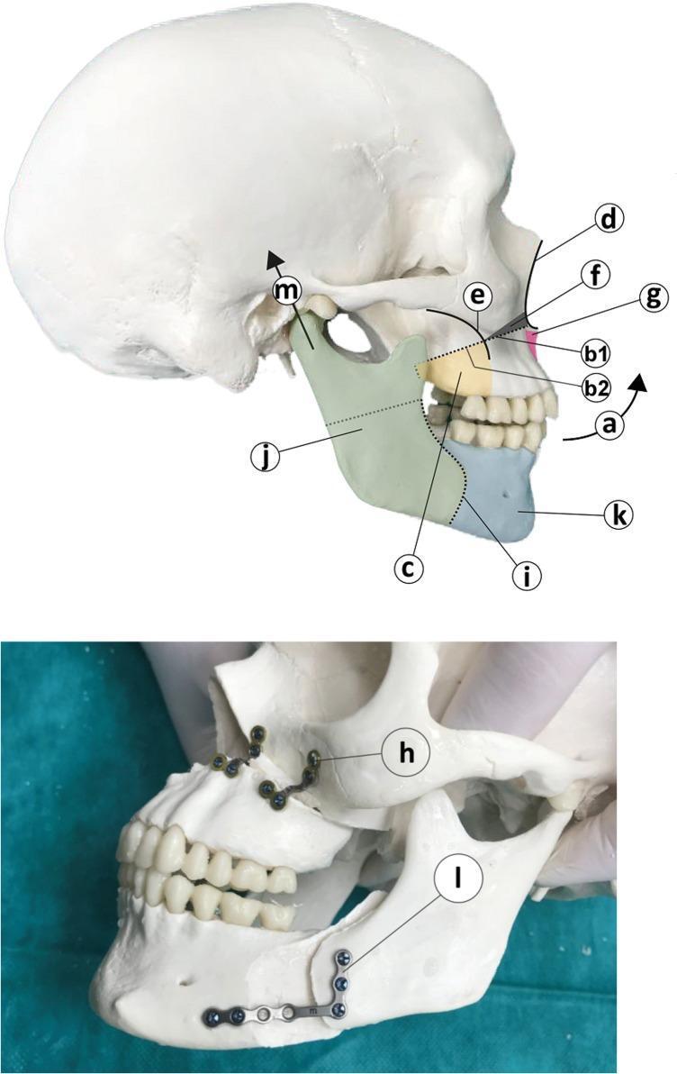
This medical illustration and corresponding clinical model photograph demonstrate the surgical steps of a bimaxillary advancement procedure with counter-clockwise rotation (BRA). The top diagram illustrates a modified Le Fort I osteotomy involving the resection of a cuneiform (wedge-shaped) bone fragment (f) from the anterior maxilla. This resection extends from the piriformis aperture (d) to the zygomatic-alveolar arch (e), with the maximum height at the aperture. A V-shaped osteotomy of the anterior nasal process (g) is indicated to prevent nasal septum compression. For the mandible, an Obwegeser-Dalpont sagittal split osteotomy (i) is shown, dividing the bone into a posterior (j) and anterior (k) segment, allowing for the advancement and cranial alignment (m) of the articular process. The bottom photograph shows the post-osteotomy fixation on a skull model. Rigid fixation of the maxilla is achieved using L-shaped mini-osteosynthesis plates (h) secured with four screws each. The mandibular segments are stabilized using a semirigid osteosynthesis miniplate (l) with multiple mini-screws. This procedure is commonly utilized in oral and maxillofacial surgery to treat obstructive sleep apnea (OSA) by expanding the pharyngeal airway.
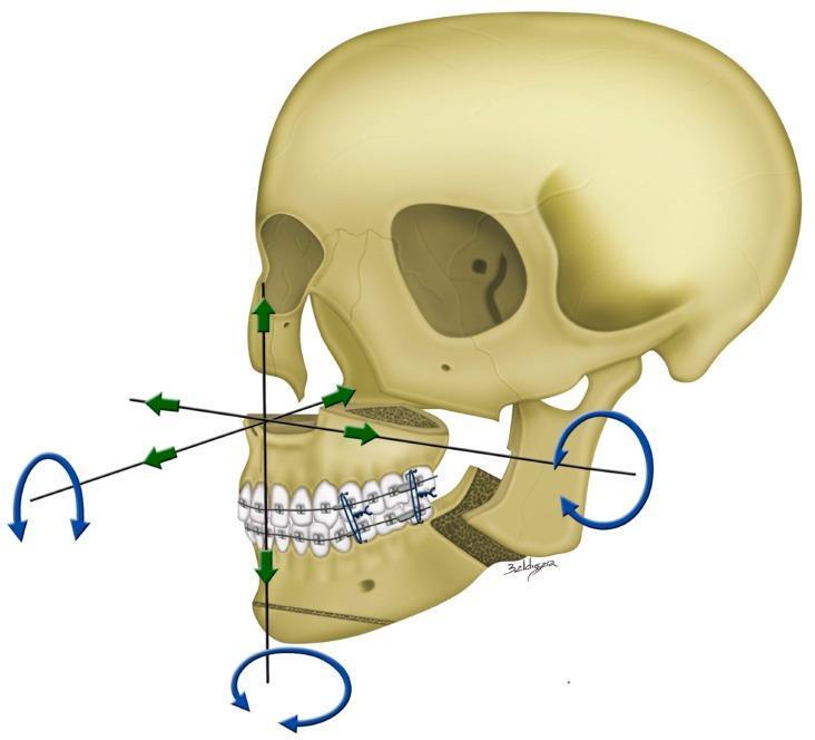
This medical anatomical diagram illustrates the principles of single-splint two-jaw orthognathic surgery on a human skull model. The illustration depicts a Le Fort I maxillary osteotomy and a bilateral sagittal split osteotomy (BSSO) of the mandible, showing the separation of the proximal ramus segments from the distal tooth-bearing segment. A 3D-printed surgical-occlusion splint and orthodontic brackets are visible, maintaining the maxillomandibular complex (MMC) in a unified position. The diagram utilizes a 3D coordinate system to show surgical degrees of freedom: green arrows represent en-bloc linear translations including advancement/setback (antero-posterior), left/right shift (horizontal), and extrusion/intrusion (vertical). Blue curved arrows indicate rotational movements: pitch (rotation around the lateral axis), roll (rotation around the sagittal axis), and yaw (rotation around the vertical axis). This visual serves as a guide for 3D computer-assisted surgical planning and the mobilization of the integrated MMC to a simulated ideal position during maxillofacial reconstruction.
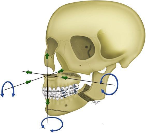
This medical anatomical diagram illustrates the principles of two-jaw orthognathic surgery using a single-splint technique for skeletofacial reconstruction. The illustration depicts a human skull with a Le Fort I osteotomy of the maxilla and a bilateral sagittal split osteotomy (BSSO) of the mandibular ramus. These procedures separate the maxilla and the distal segment of the mandible, which are then integrated into a single 'maxillo-mandibular complex' (MMC) using a surgical occlusion splint and orthodontic hardware. The diagram uses colored arrows to represent the six degrees of freedom in 3D surgical planning and movement. Green linear arrows indicate en-bloc translational movements along the X, Y, and Z axes, including horizontal shifts (left/right), antero-posterior movements (advancement/setback), and vertical movements (intrusion/extrusion). Blue curved arrows represent rotational movements, specifically pitch, roll, and yaw. This visual aid is designed for surgical education in maxillofacial and plastic surgery, demonstrating how virtual 3D simulations are transferred to physical skeletal repositioning during corrective jaw surgery.
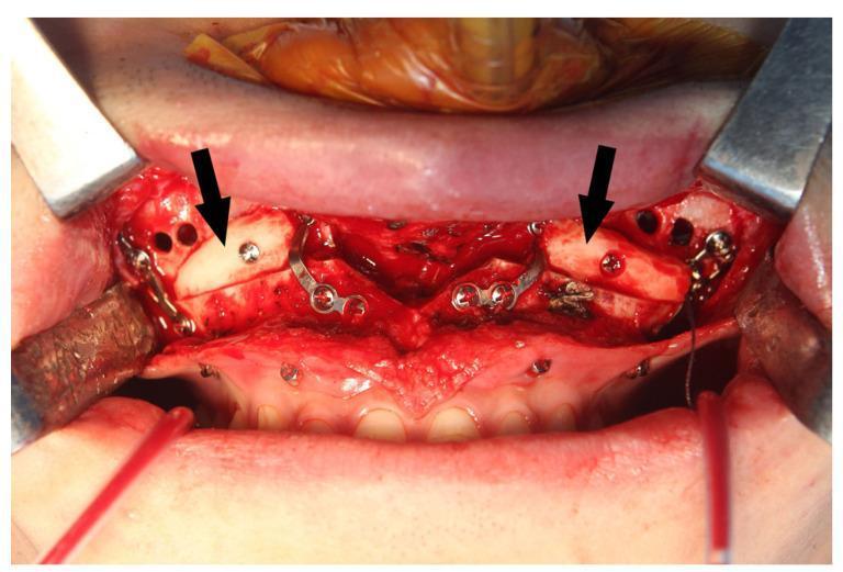
An intraoperative clinical photograph showing a Le Fort I osteotomy site in the anterior maxilla during bimaxillary orthognathic surgery. The surgical field is exposed using metal retractors, revealing the maxillary bone superior to the upper dentition. Two autogenous bone blocks (indicated by black arrows) are grafted bilaterally at the maxillary sinus wall gaps to ensure postoperative stability and facilitate sinus drainage. These pale, dense bone grafts are secured into position using titanium osteosynthesis screws. Multiple L-shaped and straight metal fixation plates are visible, bridging the osteotomy lines. Additionally, several small, circular drainage holes are drilled into the anterior maxillary wall, intended for the placement of Maxillary Sinus Vacuum Drainage (MSVD) tubes. The image demonstrates complex maxillofacial reconstruction techniques, highlighting the integration of rigid internal fixation, autogenous grafting, and sinus management protocols.
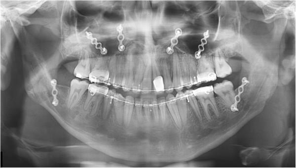
This panoramic dental radiograph (orthopantomogram) displays the postoperative status of a patient following bimaxillary orthognathic surgery. The image shows the complete maxillary and mandibular arches with comprehensive fixed orthodontic appliances (braces) consisting of brackets and continuous archwires. Radiopaque surgical hardware is prominent: four titanium miniplates are secured with monocortical screws across the maxillary Le Fort I osteotomy site along the zygomaticomaxillary and nasomaxillary buttresses. In the mandible, bilateral miniplates and screws are visible at the ramus-body junction, indicating fixation following a bilateral sagittal split osteotomy (BSSO). The anatomical landmarks, including the maxillary sinuses, nasal cavity, and mandibular condyles, are well-visualized. The hardware orientation demonstrates rigid internal fixation designed to stabilize the skeletal segments during bone healing. This image is an educational example of postoperative imaging in oral and maxillofacial surgery for the correction of dentofacial deformities like facial asymmetry and malocclusion.
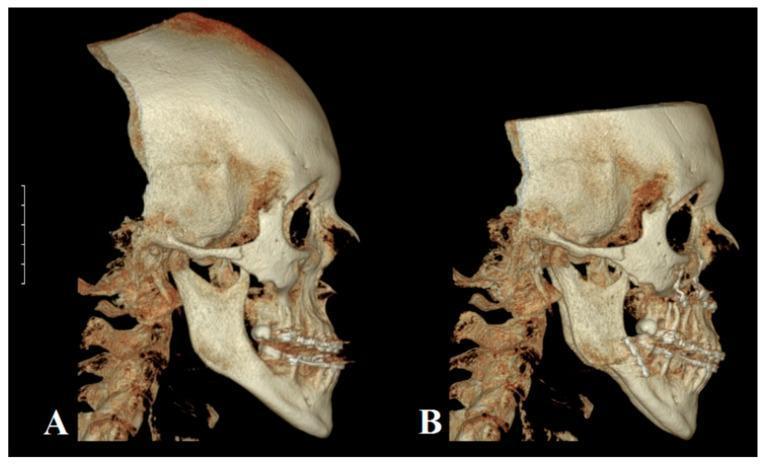
This diagnostic image displays a comparison of two 3D-reconstructed Cone Beam Computed Tomography (CBCT) scans of a human skull in a profile (lateral) view, illustrating the surgical correction of skeletal Class III malocclusion. Image A (pre-surgical) shows significant mandibular protrusion (prognathism) relative to the maxilla, resulting in a concave facial profile and reversed incisor overjet. Image B (post-surgical) demonstrates the result of bimaxillary orthognathic surgery. Specifically, it shows the outcome of a Le Fort I osteotomy used to advance the maxilla and a Bilateral Sagittal Split Osteotomy (BSSO) used to retrude the mandible. Radiopaque (white) osteosynthesis hardware, including plates and screws, is clearly visible along the osteotomy sites in both the maxilla and the mandibular ramus/body. The post-surgical reconstruction reveals a corrected neutral (orthognathic) profile with improved sagittal alignment of the upper and lower jaws and restored dental occlusion.
cephalometric landmarks SNA SNB ANB facial analysis
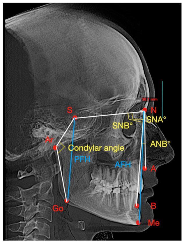
A lateral cephalometric radiograph displaying a standardized orthodontic and maxillofacial tracing used for skeletal analysis. The image identifies key anatomical landmarks marked with red dots, including the Sella (S), Nasion (N), Articulare (Ar), Gonion (Go), Menton (Me), and Points A (Subspinale) and B (Supramentale). White linear tracings connect these points to establish planes for angular measurements. Yellow arcs designate specific skeletal angles: SNA (maxillary position relative to the cranial base), SNB (mandibular position), ANB (intermaxillary relationship), and the condylar angle (S-Ar-Go). Additionally, blue vertical lines represent linear measurements for facial height analysis, specifically Posterior Facial Height (PFH) and Anterior Facial Height (AFH). This diagnostic tool is clinically significant for evaluating sagittal and vertical jaw relationships, planning orthodontic treatment, and assessing craniofacial growth or treatment outcomes in patients with temporomandibular disorders (TMD) or malocclusions.
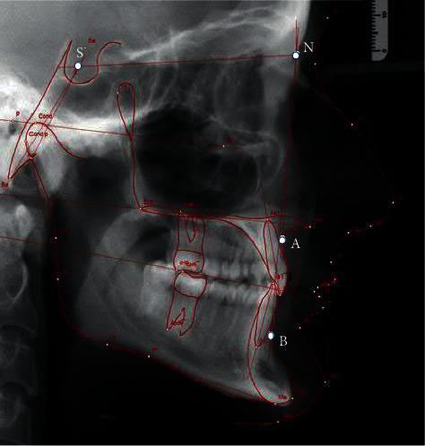
This diagnostic image is a lateral cephalogram, a standardized orthodontic X-ray providing a sagittal view of the human skull, facial bones, and soft tissue profile. The radiography demonstrates key anatomical landmarks used in cephalometric analysis. Traced in red are skeletal outlines including the cranial base, sella turcica, maxilla, and mandible. Specific cephalometric points are highlighted: S (Sella), N (Nasion), A (Subspinale), and B (Supramentale). These points facilitate the measurement of angles such as SNA, SNB, and ANB to evaluate the anteroposterior relationship of the jaws and determine facial types (orthognathic, retrognathic, or prognathic). The image clearly depicts the dentition, showing the inclination of the maxillary and mandibular incisors relative to their respective basal bones. This clinical tool is essential for orthodontic diagnosis, treatment planning for malocclusions, and assessing craniofacial growth or surgical outcomes in maxillofacial procedures.
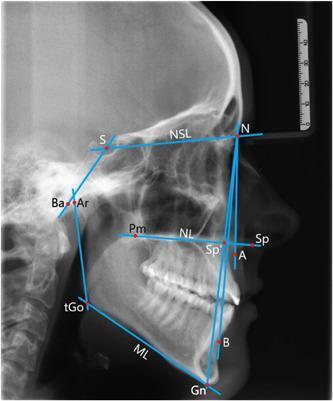
This diagnostic image is a lateral cephalogram, a specialized orthodontic X-ray of the human skull in profile. It features an overlay of blue geometric lines and red landmark points used for cephalometric analysis. Key anatomical landmarks identified include Sella (S), Nasion (N), A-point (A), B-point (B), Gnathion (Gn), Gonion (Go), and Articulare (Ar). The image illustrates several diagnostic variables: the SNA, SNB, and ANB angles for assessing the sagittal relationship of the maxilla and mandible relative to the cranial base; the NSBa angle for cranial base flexure; and the ML-NSL, NL-NSL, and ML-NL angles for evaluating vertical growth patterns and the inclination of the nasal and mandibular planes. The radiograph clearly shows the skeletal structures of the cranium, facial bones, dentition, and upper cervical vertebrae. This material is primarily used in orthodontics and maxillofacial surgery for treatment planning and growth monitoring.
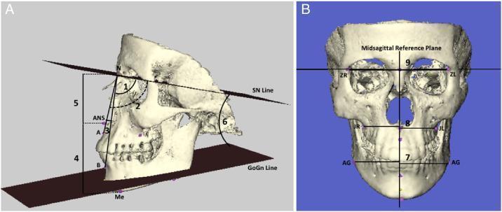
Educational medical illustration featuring 3D reconstructed skull models for cephalometric analysis, divided into lateral and posteroanterior views. Panel A demonstrates lateral cephalometric measurements including: angular relationships between the anterior cranial base (SN line) and the maxilla (SNA angle, 1), mandible (SNB angle, 2), and maxillomandibular discrepancy (ANB angle, 3); mandibular plane inclination relative to the cranial base (GoGn/SN angle, 6); and linear vertical measurements for anterior upper facial height (N-ANS, 5) and lower facial height (ANS-Me, 4). Panel B shows a posteroanterior (PA) view illustrating facial symmetry analysis relative to the Midsagittal Reference Plane (MSR). It highlights linear distances from the MSR to bilateral landmarks: the frontozygomatic sutures (ZL/ZR, 9), alveolar maxillary processes (JL/JR, 8), and antegonial notches (AG, 7). These diagrams illustrate the standard radiological landmarks used in orthodontics and maxillofacial surgery to assess skeletal growth patterns and craniofacial asymmetry.
facebow transfer articulator model surgery dental casts splint
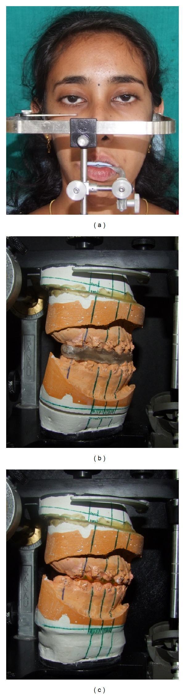
A multi-part clinical and laboratory image illustrating presurgical planning for orthognathic surgery. (a) Frontal clinical photograph of a female patient during a facebow transfer. A metallic facebow is stabilized using ear rods and an infraorbital pointer, with a bite fork inserted intraorally to record the relationship of the maxillary arch to the temporomandibular joints and horizontal reference plane. (b) and (c) Show model surgery performed on dental casts mounted on a Hanau articulator. The casts feature reference lines drawn across the dental bases to track vertical and horizontal movements. Figure (b) demonstrates the use of an intermediate acrylic occlusal splint, which records the planned repositioning of the maxilla relative to the unoperated mandible. Figure (c) shows the final occlusal splint in place, representing the desired post-surgical intercuspation and alignment of both the maxillary and mandibular arches. This sequence illustrates the transition from clinical recording to laboratory simulation for correcting skeletal malocclusions.
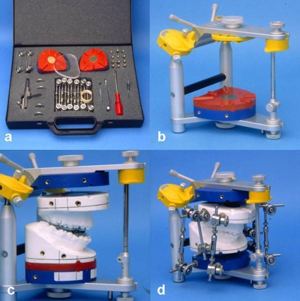
A series of four clinical photographs illustrating the Calibrated Double Splint - Münster Model Surgery System (KD-MMS), a specialized orthognathic surgical planning tool. Frame (a) shows the hardware kit, including red and clear split plates, precision screws, and specialized screwdrivers. Frame (b) depicts a SAM-P articulator with integrated red and blue double split plates mounted on the lower member, serving as a standardized reference base. Frame (c) shows white plaster dental casts mounted within the articulator; the setup is oriented parallel to the Axis Orbital Plane to facilitate precise simulation of maxillary displacement. Frame (d) demonstrates the final pre-surgical configuration, where the repositioned dental models are stabilized using a system of adjustable metal rods and screws. This device allows for the translation of two-dimensional cephalometric prediction planning into a three-dimensional model surgery environment for the treatment of dentofacial deformities and malocclusions.
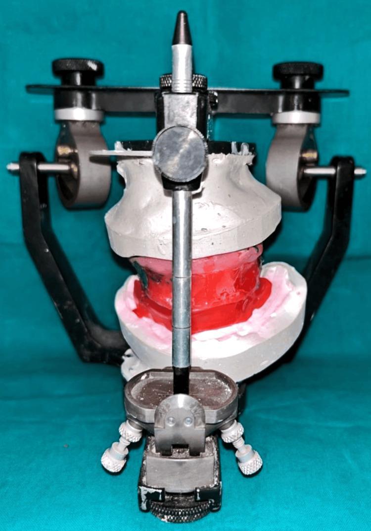
A clinical photograph depicting a Hanau Wide-Vue semi-adjustable articulator, a diagnostic and procedural tool used in prosthodontics and oral surgery. The image shows the frontal view of the device with maxillary and mandibular dental casts mounted. The articulator's upper member is connected to the lower member via a central vertical incisal pin and lateral condylar guidance mechanisms, which feature adjustable black knobs for setting condylar inclination. The maxillary (upper) and mandibular (lower) diagnostic casts are fabricated from white dental stone. Between the casts, a red and pink wax bite registration is positioned to record the maxillomandibular relationship. The setup represents a facebow transfer, utilized here to orient the maxillary cast to the articulator's hinge axis, facilitating the restoration of vertical dimension and occlusal rehabilitation in a complex implant-supported case. The clinical relevance involves pre-prosthetic planning for zygomatic and endosteal implant placement to correct severe maxillary atrophy and occlusal dysfunction.
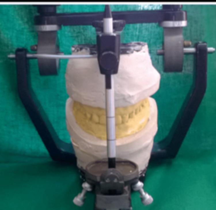
This procedural dental photograph shows a maxillary and mandibular diagnostic study model mounted on a semi-adjustable articulator. The device consists of a dark metallic frame with an incisal pin positioned vertically at the anterior, marked with graduated linear divisions to establish and maintain vertical dimension. The dental casts are made of white gypsum plaster, with the tooth regions highlighted in a contrasting yellow material, likely representing a wax-up or a specific dental stone for enhanced visualization of the occlusion. The maxillary cast is rigidly attached to the upper member of the articulator, while the mandibular cast is fixed to the lower member, replicating the patient's maxillomandibular relationship recorded via a facebow and interocclusal records. This setup is a critical step in prosthodontic treatment planning, allowing for the evaluation of occlusion, mock preparations, and the design of restorative interventions such as laminate veneers.
mandibular autorotation maxillary impaction orthognathic
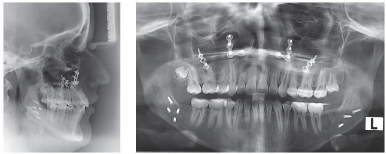
This composite of diagnostic images includes a lateral cephalometric radiograph and a panoramic radiograph showing the maxillofacial region of a post-surgical patient. The radiographs demonstrate the outcome of orthognathic surgery, specifically a bimaxillary procedure involving maxillary impaction and mandibular setback. Key findings include multiple radiopaque metallic hardware: bilateral Y-shaped zygomatic plates secured with screws in the maxilla and orthodontic miniscrews positioned between the canines and bicuspids in the mandible. The panoramic view shows a full dental arch with several radiopaque dental restorations (fillings) and evidence of endodontic treatment (root canals). The mandibular condyles are visible and symmetrical, and the alveolar bone height appears well-maintained. The lateral cephalogram highlights the skeletal profile changes, showing the soft tissue silhouette and the counterclockwise rotation of the maxillomandibular complex. These findings are consistent with orthodontic-surgical management of Class III malocclusion and condylar hyperplasia, showcasing final stabilization with skeletal anchorage and rigid internal fixation.
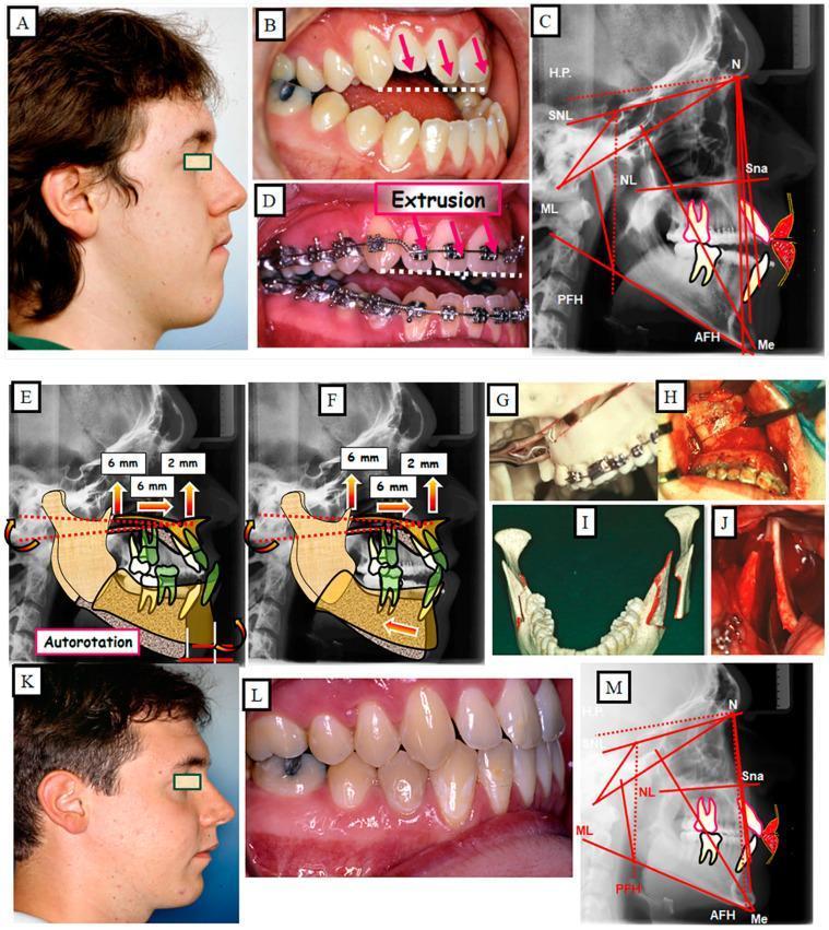
A multi-panel clinical educational figure documenting the surgical and orthodontic treatment of a 23-year-old male with a combined skeletal and dental anterior open bite. (A-C) Pre-treatment profile showing an elongated lower facial third, an intraoral view of severe anterior infraocclusion with red arrows indicating the vertical gap, and a lateral cephalogram with tracings (SNL, NL, ML) highlighting hyperdivergent jaw bases. (D) Pre-surgical orthodontic phase showing fixed appliances and the extrusion of anterior teeth. (E-F) Cephalometric surgical simulations demonstrating maxillary impaction (6mm) and resultant mandibular autorotation to close the vertical discrepancy and adjust the sagittal position. (G-J) Intraoperative photographs and 3D models illustrating the Le Fort I osteotomy for maxillary impaction and bilateral sagittal split osteotomy (BSSO) for mandibular adjustment with internal fixation. (K-M) Post-treatment results showing a reduced lower facial height, achieved dental occlusion with corrected overbite/overjet, and normalized cephalometric parameters. The content illustrates orthognathic surgical planning for long face syndrome and complex malocclusion.
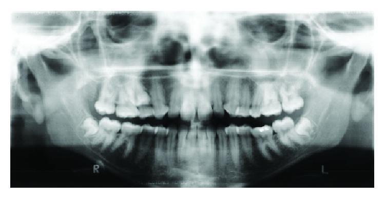
This diagnostic image is a pretreatment panoramic radiograph (orthopantomogram) of a 17-year-old female patient, illustrating significant dental impactions and malocclusion. The radiograph reveals a full permanent dentition with three primary areas of impaction: both mandibular third molars are horizontally impacted against the distal aspect of the second molars, and the maxillary right second premolar is impacted in a high superior position near the floor of the maxillary sinus. The dental alignment demonstrates signs of irregularity and crowding, particularly in the anterior regions, consistent with a clinical diagnosis of Class III malocclusion. The maxillary arch appears constricted, while the mandibular arch shows slight anterior crowding. Supporting anatomical structures, including the mandibular condyles, ramus, and maxillary sinuses, are visible. This imaging is clinically significant for orthodontic and orthognathic surgical planning, providing a comprehensive view of tooth angulation and the spatial relationship between impacted elements and surrounding bone.
Treatment Planning for Orthognathic Surgery
Based on Reyneke's "Essentials of Orthognathic Surgery," 2nd ed.
Introduction
1. Clinical Examination
Extraoral Assessment
- Facial thirds: The face is divided into upper (trichion-glabella), middle (glabella-subnasale), and lower (subnasale-menton) thirds. All three should be roughly equal in a balanced face.
- Anterior facial height: Excess LAFH suggests vertical maxillary excess ("long face"); deficiency suggests short face.
- Facial profile: Convex (Class II), concave (Class III), or straight (Class I).
- Lip competence: Assess lip seal at rest, amount of upper incisor and gingival display at rest and on full smile.
- Chin morphology: AP projection and vertical height.
- Transverse symmetry: Facial midline, chin deviation, jaw asymmetry.
Intraoral Assessment
- Angle classification (Class I, II, III)
- Overjet and overbite
- Dental midlines
- Transverse arch width and crossbites
- Curve of Spee
- Dental compensations (must be identified for pre-surgical decompensation)
2. Cephalometric Analysis
Key Skeletal Measurements
| Parameter | Normal Value | Significance |
|---|---|---|
| SNA | 82° ± 2° | Maxillary AP position to cranial base |
| SNB | 80° ± 2° | Mandibular AP position to cranial base |
| ANB | 2° ± 2° | Sagittal intermaxillary relationship |
| Wits appraisal | 0 mm (F), -1 mm (M) | Functional occlusal plane jaw relationship |
| Facial axis (Ba-N to Pt-Gn) | 90° | Direction of condylar growth |
| Lower anterior facial height | ~55% of total AFH | Vertical proportion |
| Gonial angle | 130° ± 7° | Mandibular morphology |
| Palatal plane to SN | 8° ± 3° | Maxillary inclination |
Key Dental Measurements
| Parameter | Normal Value |
|---|---|
| U1 to NA (angle) | 22° |
| U1 to NA (linear) | 4 mm |
| L1 to NB (angle) | 25° |
| L1 to NB (linear) | 4 mm |
| IMPA (L1 to mandibular plane) | 90° ± 5° |
| Interincisal angle | 130° ± 10° |
Soft Tissue Parameters
- Nasolabial angle: 90-110°
- Holdaway H-angle: 7-15°
- Upper lip to incisor at rest: 1-4 mm show
3. Pre-surgical Records
- Standardized facial photographs (frontal, profile, 3/4 view, smiling)
- Intraoral photographs
- Lateral and PA cephalometric radiographs
- Panoramic radiograph (OPG)
- Dental study models
- Facebow record
4. Pre-surgical Orthodontics
- Decompensate dental compensations (e.g., in Class III, upright the proclined lower incisors and retroclined upper incisors; this temporarily worsens the clinical appearance - the patient must be counseled)
- Level and align each arch independently
- Coordinate arch widths to correct transverse discrepancies
- Establish ideal arch form so the planned post-surgical occlusion is achievable
Reyneke's rule: Surgery must never compensate for orthodontic inadequacy. If the teeth are not properly prepared, the surgery will not achieve the planned result.
5. Model Surgery on the Articulator
Step 1 - Facebow Transfer
Step 2 - Mounting on Articulator
Step 3 - Maxilla-First Model Surgery (Reyneke's Sequence)
1. Reposition MAXILLA to planned position
         ↓
2. Construct INTERMEDIATE WAFER (records post-maxillary / pre-mandibular occlusion)
         ↓
3. Allow mandible to AUTOROTATE to new position
         ↓
4. Reposition MANDIBLE as required
         ↓
5. Construct FINAL WAFER (records definitive planned occlusion)
6. The Autorotation Concept (Reyneke's Key Teaching)
- A 4-6 mm maxillary impaction can advance the chin point by 3-4 mm and reduce LAFH significantly
- This may eliminate the need for mandibular surgery in some borderline cases
- Failure to account for autorotation results in unanticipated chin movement
7. Surgical Prediction Tracing (Visualized Treatment Objective - VTO)
- Trace the current cephalogram
- Cut and reposition the bony segments according to planned movements
- Predict soft tissue response using established ratios:
- Upper lip: moves with maxilla at ~50-70%
- Lower lip: follows mandibular incisor at ~80-100%
- Chin soft tissue: follows hard tissue Pogonion at ~90-100%
- Nasal tip: elevates slightly with maxillary impaction
8. Virtual Surgical Planning (VSP)
- Three-dimensional simulation of all bony movements (6 degrees of freedom)
- Superior accuracy for asymmetry correction
- CAD/CAM-fabricated cutting guides and printed surgical splints
- Prediction of soft tissue changes in 3D
9. Determining Surgical Movements
| Plane | Movements |
|---|---|
| Sagittal (AP) | Maxillary advancement/setback; mandibular advancement/setback |
| Vertical | Maxillary impaction/downgraft; vertical genioplasty |
| Transverse | Midline correction, asymmetry correction, expansion |
10. Surgical Sequence and Osteotomies
Standard Bimaxillary Sequence
Le Fort I Osteotomy (maxilla) → Intermediate wafer in place
         ↓
Maxilla fixed with titanium plates and screws
         ↓
Bilateral Sagittal Split Osteotomy (BSSO) - mandible
         ↓
Final wafer guides mandibular position → Fixed with plates/screws
         ↓
Genioplasty (if required) - last step
11. Stability Hierarchy (Reyneke after Proffit)
| Movement | Stability |
|---|---|
| Maxillary impaction | Most stable |
| Mandibular advancement (with rigid fixation) | Very stable |
| Maxillary advancement | Stable |
| SARPE (transverse expansion) | Moderate |
| Mandibular setback | Less stable (muscular/soft tissue relapse) |
| Maxillary downgraft | Least stable |
12. Post-surgical Orthodontics
- Detailing of the occlusion (minor tooth movements that surgery cannot achieve)
- Closure of residual spaces
- Finishing and retention
Multidisciplinary Team
| Team Member | Role |
|---|---|
| Oral & Maxillofacial Surgeon | Surgical planning and execution |
| Orthodontist | Pre- and post-surgical tooth movements |
| Prosthodontist | Restorative dental rehabilitation if needed |
| Speech Therapist | For mandibular advancement or cleft cases |
| Psychologist | Patient expectations and body image |
Summary - Reyneke's 10-Step Protocol
| Step | Action |
|---|---|
| 1 | Clinical examination (facial, dental, TMJ) |
| 2 | Cephalometric and radiographic analysis |
| 3 | Problem list and treatment objectives |
| 4 | Pre-surgical orthodontics (decompensation + alignment) |
| 5 | Final pre-surgical records |
| 6 | Model surgery on semi-adjustable articulator (maxilla first) |
| 7 | Prediction tracing / VTO / VSP |
| 8 | Intermediate and final wafer fabrication |
| 9 | Surgery (Le Fort I → BSSO → genioplasty) |
| 10 | Post-surgical orthodontics and retention |
Key Reyneke Principles to Memorize
- Maxilla first in both planning and surgery - it is the reference jaw
- Autorotation - always account for mandibular movement after maxillary repositioning
- Vertical dimension is established first before AP and transverse corrections
- Pre-surgical decompensation is mandatory - surgery never compensates for orthodontic deficiency
- Intermediate + final wafers - the two surgical guides that translate planning to the operating table
- Impaction > advancement > setback > downgraft in terms of stability
- Soft tissue prediction must validate skeletal planning before surgery is performed