Breathing systems in anaesthesia comprehensive review
Reading File
Finding Sources
Finding Sources
Searching PubMed
"breathing systems" AND anaesthesia
Finding Sources
Finding Sources
Finding Sources
Finding Sources
Finding Sources
Reading File
Reading File
Reading File
Reading File
Reading File
Reading File
Loading Image
Loading Image
Excellent — I now have all the core content and key diagrams. Let me compile the comprehensive review.
Breathing Systems in Anaesthesia — Comprehensive Review
Sources: Miller's Anesthesia 10e, Morgan & Mikhail's Clinical Anesthesiology 7e, Barash Clinical Anesthesia 9e
1. Overview and Classification
Fresh gas departs the anaesthetic machine's common gas outlet and enters the breathing circuit through the fresh gas line. The functions of any breathing circuit are to:
- Deliver oxygen and anaesthetic gases to the patient
- Eliminate CO₂
- Provide a reservoir to meet peak inspiratory flow demands
- Vent excess gas via an expiratory port or valve
Breathing systems are fundamentally classified by whether they use a CO₂ absorber:
| Category | CO₂ Elimination | Examples |
|---|---|---|
| Absorber systems | Chemical absorption | Circle system |
| Non-absorber (washout) systems | High fresh gas flow | Mapleson A–F |
A further classification uses the degree of rebreathing:
| Type | Description |
|---|---|
| Open | No rebreathing; gases not confined (e.g. insufflation) |
| Semi-open | Reservoir present, no rebreathing (e.g. Ayre's T-piece at high flow) |
| Semi-closed | Partial rebreathing with overflow (circle or Mapleson at moderate FGF) |
| Closed | Complete rebreathing; no overflow valve open; FGF = metabolic uptake |
2. Components Common to All Systems
Fresh Gas Inlet (FGI)
- Delivers O₂, N₂O, air, and volatile agent from the machine's common gas outlet (CGO)
- Oxygen flush valve bypasses vaporisers and flowmeters, delivering 35–75 L/min at line pressure (45–55 psig) — risk of barotrauma if activated when patient is connected
Reservoir Bag (Breathing Bag)
- Latex or silicone, typically 2 L for adults
- Serves as: (a) reservoir for gas during expiration; (b) tool for manual ventilation; (c) visual monitor of spontaneous breathing; (d) pressure-limiting safety device (maximum ~60 cmH₂O)
- APL valve should be fully open during spontaneous ventilation so circuit pressure remains negligible
Corrugated Breathing Tubes (Limbs)
- Standard: 22 mm internal diameter, 110 cm length
- High compliance = increased difference between volume delivered to circuit and volume reaching patient — clinically significant at low tidal volumes (paediatrics)
- Apparatus dead space extends only to the Y-piece in the circle system (not affected by tube length, unlike Mapleson circuits)
Adjustable Pressure-Limiting (APL) / Pop-off Valve
- Spring-loaded, pressure-adjustable overflow valve
- Open during spontaneous breathing; partially/fully closed during manual positive pressure ventilation
- Excess gas diverted to waste gas scavenging system
Y-piece
- Connects inspiratory and expiratory limbs to the patient's airway device
- The only portion of the circle system that represents apparatus dead space (beyond the Y-piece, inspiratory and expiratory gas mix)
3. The Circle System
The circle system is the most widely used anaesthetic breathing circuit worldwide.
3.1 Essential Components (7 core elements)
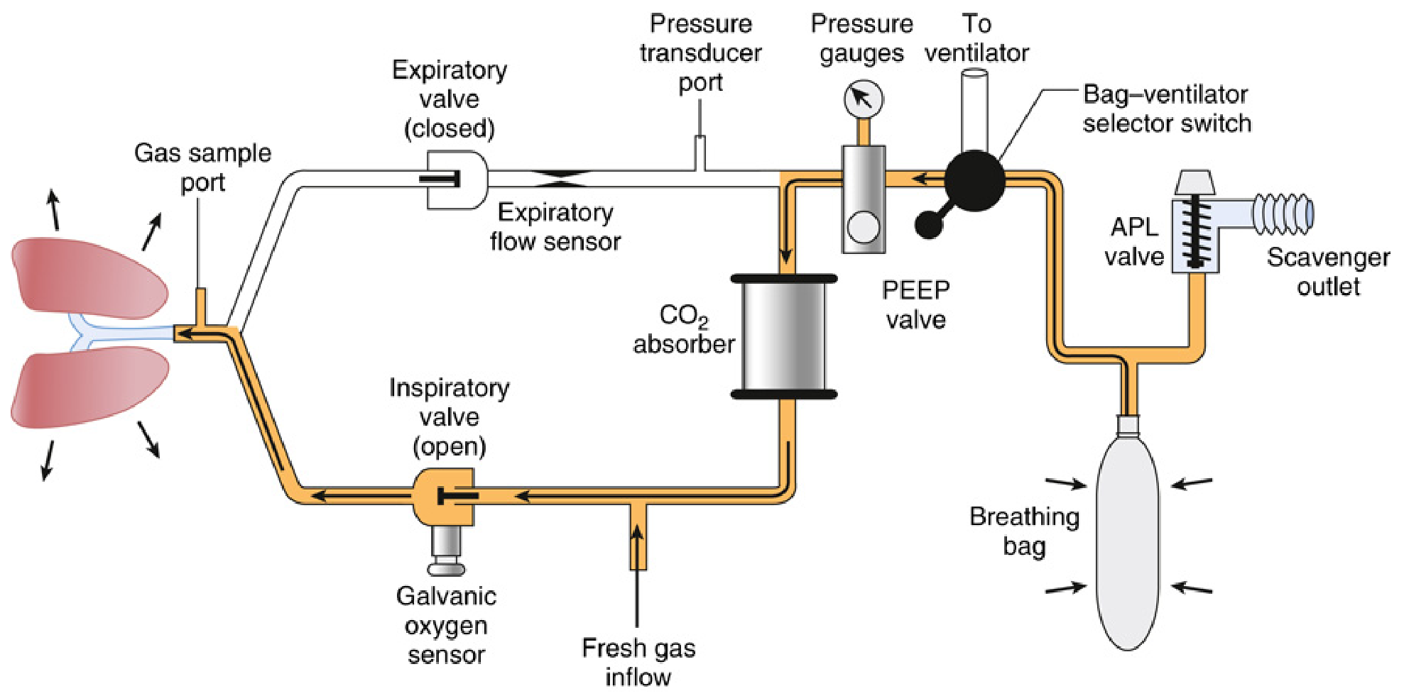
- Fresh gas inflow source
- Inspiratory unidirectional valve (allows gas flow toward patient only)
- Expiratory unidirectional valve (allows gas flow away from patient only)
- Inspiratory and expiratory corrugated tubes
- Y-piece (patient connection)
- APL (pop-off) valve
- Reservoir/breathing bag
- CO₂ absorber canister
Additional safety components: circuit pressure sensor/gauge, expiratory (± inspiratory) flow sensor, inspired O₂ concentration analyser, PEEP valve.
3.2 Gas Flow in the Circle System
- Inspiration: Patient draws gas from the breathing bag → through CO₂ absorber → mixed with FGI → through inspiratory valve → to patient
- Expiration: Exhaled gas passes through expiratory valve → toward CO₂ absorber and reservoir bag
- The unidirectional valves prevent mixing of inspiratory and expiratory gases proximal to the Y-piece, keeping apparatus dead space minimal
3.3 Rules to Prevent CO₂ Rebreathing (Circle System)
Three rules must be followed:
- A unidirectional valve must be on both the inspiratory and expiratory limbs between the patient and the reservoir bag
- Fresh gas inflow cannot enter the circuit between the expiratory valve and the patient
- The APL valve cannot be located between the patient and the inspiratory valve
Malfunction of either unidirectional valve allows rebreathing of CO₂ → hypercapnia.
3.4 Advantages of the Circle System
| Advantage | Mechanism |
|---|---|
| Stable inspired gas concentrations | Rebreathing + absorber dampens fluctuations |
| Conservation of anaesthetic agents | Rebreathing at low FGF |
| Conservation of heat & moisture | Exhaled humidified gas recycled |
| Efficient CO₂ removal | Chemical absorption |
| Reduced OR pollution | Scavenging + low FGF |
| Economical gas use | Low/minimal FGF possible |
3.5 Fresh Gas Flow (FGF) Strategies in the Circle System
| Strategy | FGF | Characteristics |
|---|---|---|
| High flow | >4 L/min | Rapid changes in inspired concentration; washes out N₂; prevents rebreathing without absorber |
| Low flow | 0.5–1 L/min | Relies on absorber; economical; retains heat/moisture; slow changes in circuit gas composition |
| Minimal flow | ~0.3 L/min | FGF = O₂ uptake + N₂O uptake; near-complete rebreathing |
| Closed system | = metabolic uptake | No gas escapes; FGF = O₂ consumption only (~200–250 mL/min); APL valve closed |
4. CO₂ Absorbers
4.1 Soda Lime
The most common CO₂ absorbent.
- Composition: Calcium hydroxide ~80%, sodium hydroxide ~4%, potassium hydroxide 1%, water 14–19%, silica (hardens granules, reduces dust inhalation risk and airflow resistance)
- Granule size: 4–8 mesh (4 mesh = 4 openings per inch) — balance between surface area and resistance
- Capacity: 1 g absorbs ~0.26 L CO₂; a 1 kg canister absorbs ~120 L CO₂
- Colour indicators: Most turn purple/violet when exhausted (e.g. ethyl violet). May regenerate (reverse colour) if not used — deceptive appearance of fresh absorbent; always verify with capnograph
4.2 Chemical Reactions (Soda Lime)
CO₂ + H₂O → H₂CO₃ (carbonic acid)
H₂CO₃ + 2NaOH → Na₂CO₃ + 2H₂O + heat
H₂CO₃ + 2KOH → K₂CO₃ + 2H₂O + heat
Na₂CO₃ + Ca(OH)₂ → CaCO₃ + 2NaOH (regenerates NaOH)
The reaction is exothermic — a warm canister indicates active CO₂ absorption; a cool canister suggests exhaustion.
4.3 Newer Absorbents
Modern absorbents aim to eliminate strong bases (NaOH, KOH) that cause volatile anaesthetic degradation:
| Absorbent | NaOH/KOH | Compound A | CO | Notes |
|---|---|---|---|---|
| Soda lime | Yes (small) | Minimal | Minimal | Standard |
| Baralyme | Yes | Higher | Higher | Largely withdrawn |
| Amsorb Plus | No | None | None | Ca(OH)₂ + CaCl₂; safe with all agents |
| Drägersorb Free | No | None | None | Lithium-based |
| Medisorb | No | None | None | Ca-based |
Key clinical concern: Degradation of volatile agents by strong-base absorbents:
- Sevoflurane + soda lime → Compound A (nephrotoxic in rats at high concentrations; not definitively shown harmful in humans but avoid very low FGF <1 L/min with sevoflurane for prolonged procedures per FDA labelling)
- Desflurane/isoflurane/enflurane + desiccated soda lime/Baralyme → Carbon monoxide (CO) — risk highest with Baralyme, enflurane > desflurane > isoflurane; occurs when absorbent is abnormally dry (e.g. high O₂ flow overnight through unused machine)
- Prevention: Use CO₂-absorbent free of strong bases; avoid desiccation; turn off O₂ flow at end of day
5. Mapleson Circuits (A–F)
Mapleson circuits lack a CO₂ absorber; CO₂ elimination depends entirely on fresh gas washout.
5.1 Common Components
- Patient connection (mask/ETT)
- Reservoir tubing
- Fresh gas inflow tubing
- Pop-off valve or open port
- Breathing bag (except Mapleson E)
5.2 Individual Circuits
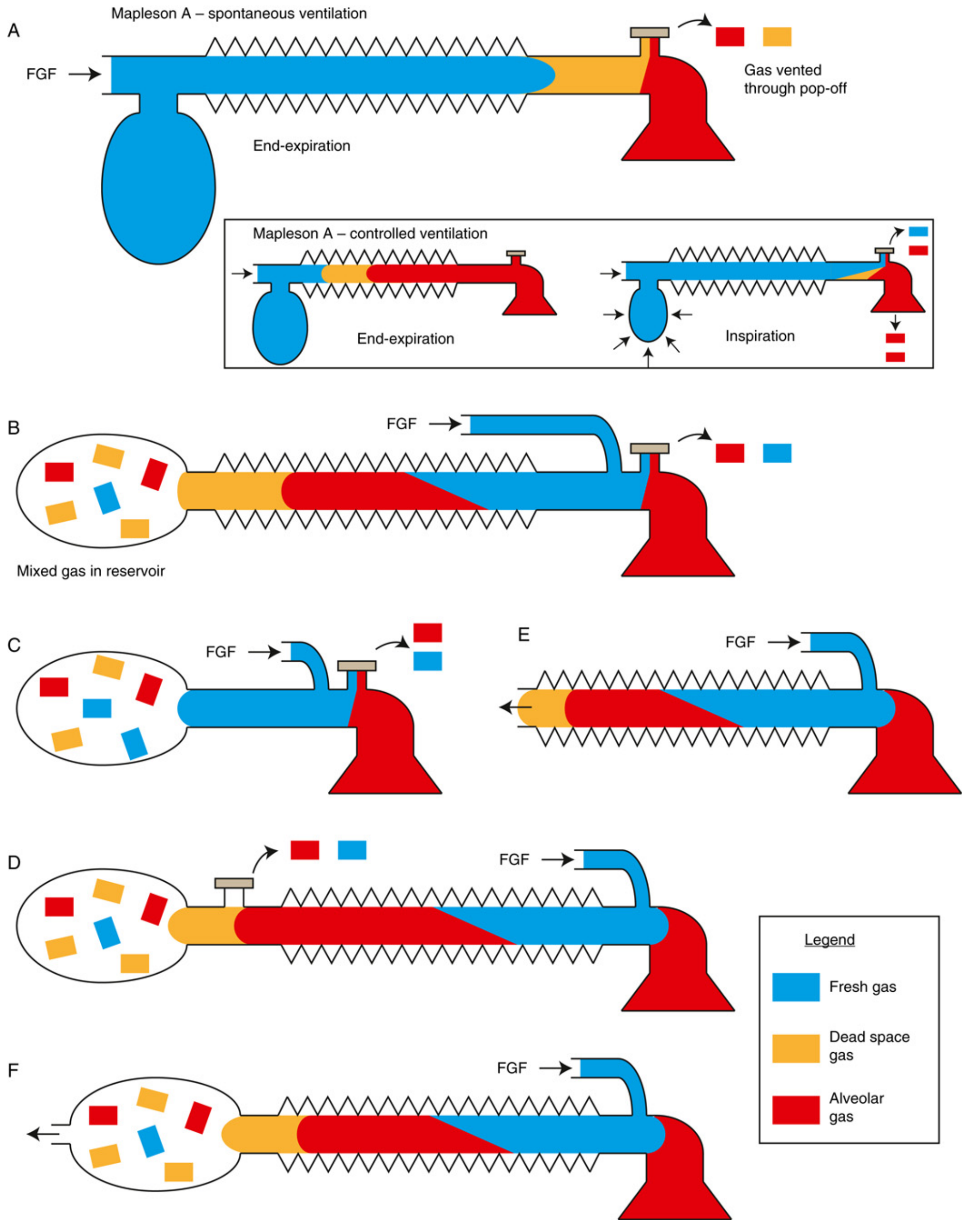
Mapleson A (Magill Circuit)
- FGI enters at machine end (bag end), far from patient
- APL valve near patient
- Most efficient for spontaneous ventilation — FGF equal to alveolar minute ventilation (~70 mL/kg/min) is sufficient to prevent rebreathing
- Why: During expiration, fresh gas fills the tubing, displacing alveolar gas out through the APL valve; only dead space gas (not alveolar gas) re-enters at the next inspiration
- Inefficient for controlled ventilation — requires FGF 2–3× minute ventilation; during manual IPPV, fresh gas is at bag end and cannot push alveolar gas toward APL valve efficiently
- Mnemonic: "A for Anaesthetist end" (FGI at anaesthetist/machine end)
Mapleson B
- FGI and APL valve both near patient (FGI proximal, APL slightly more distal)
- Reservoir tube dead-ends in a bag
- Inefficient for both spontaneous and controlled ventilation
- Rarely used clinically
Mapleson C (Waters To-and-Fro)
- Short circuit, FGI and APL both near patient, no corrugated tube
- FGI proximal, APL adjacent
- Historically used for short procedures but CO₂ absorber in original Waters canister placed inline
- The "C" without absorber is inefficient; requires FGF ~2× MV for spontaneous, ~2× MV for controlled
- Rarely used today
Mapleson D (Bain Circuit variant — coaxial Mapleson D)
- FGI near patient, APL valve at machine/bag end
- Most efficient for controlled ventilation — fresh gas pushes alveolar gas toward the APL valve
- FGF required: ~70–100 mL/kg/min (≥2.5× MV) to prevent rebreathing during controlled ventilation
- For spontaneous ventilation: FGF ~200–300 mL/kg/min needed (inefficient)
- Mapleson D = opposite of A: "D for Distant end" (FGI near patient, vents at far end)
Mapleson E (Ayre's T-piece)
- T-shaped connector, no reservoir bag and no APL valve; open expiratory limb
- FGI enters at the patient side of the T; expiratory limb acts as reservoir
- Suitable for spontaneous ventilation only (no bag for manual IPPV)
- Used for paediatrics and during weaning from mechanical ventilation
- FGF ≥2.5× MV to prevent rebreathing (expiratory limb volume must exceed tidal volume)
Mapleson F (Jackson–Rees Circuit)
- Ayre's T-piece with a bag and open tail added to the expiratory limb
- The open tail (with or without a valve) allows manual ventilation and visual monitoring of breathing
- Most popular paediatric circuit
- Efficient for both spontaneous and controlled ventilation in small patients
- FGF requirements similar to Mapleson D
5.3 Efficiency Summary Table
| Circuit | Best mode | Min FGF to prevent rebreathing |
|---|---|---|
| Mapleson A | Spontaneous | ~MV (70 mL/kg/min) |
| Mapleson B | Neither | ~2× MV |
| Mapleson C | Neither | ~2× MV |
| Mapleson D/Bain | Controlled | ~2–3× MV (spontaneous); ~70 mL/kg/min (controlled) |
| Mapleson E | Spontaneous (paediatric) | 2.5–3× MV |
| Mapleson F (Jackson–Rees) | Both (paediatric) | ~2–3× MV |
Memory aid: "A better than D for spontaneous; D better than A for controlled" — or: "All Dogs Make Furry Friends" (A, D, M[apleson], F, F for FGF hierarchy)
5.4 Advantages of Mapleson Systems
- Low resistance to gas flow
- Simple, few parts, lightweight
- Rapid changes in inspired concentration
- No volatile agent degradation (no CO₂ absorber)
- Suitable for patient transport and remote locations
5.5 Disadvantages
- Higher FGF required → higher gas/agent cost
- Poor heat and humidity conservation
- Difficult waste gas scavenging
- Risk of rebreathing at inadequate FGF
6. The Bain Circuit
A coaxial modification of the Mapleson D:
- Fresh gas flows through an inner coaxial tube from the machine to the patient end
- Expired gas travels back through the outer tube to the APL valve/bag
- Advantages: lightweight, single-tube design, less cumbersome; FGI warms slightly from surrounding expired gas
- Disadvantage: inner tube disconnection → increased dead space, unrecognised rebreathing → hypercapnia
- Pethick test (to check inner tube integrity): Occlude patient end, fill circuit with O₂ flush — if inner tube is patent, Venturi effect deflates the bag; if bag remains distended, inner tube is disconnected
7. Resuscitation (Self-Inflating) Breathing Systems
- Self-inflating bag (BVM — bag-valve-mask) does not require a gas source to function
- Contains a one-way patient valve and a reservoir bag/tube
- FiO₂ delivered is proportional to O₂ flow and reservoir design:
- No reservoir, no supplemental O₂: FiO₂ ~21%
- Supplemental O₂ at 10 L/min without reservoir: FiO₂ ~40–50%
- O₂ at 10–15 L/min with reservoir: FiO₂ ~60–100%
- Ventilation can be controlled (unlike insufflation)
8. Insufflation
- Gas directed near but not into the airway (e.g. over face)
- No direct patient contact → no rebreathing at sufficient flow
- Cannot control ventilation; inspired gas contains unpredictable entrained air → FiO₂ unreliable
- Uses: airway procedures, laryngoscopy, apnoeic oxygenation
9. Monitoring the Breathing System
| Monitor | Location | Function |
|---|---|---|
| O₂ analyser (paramagnetic/galvanic/polarographic) | Inspiratory or expiratory limb | Detect hypoxic mixture; mandatory for GA |
| Capnograph (ETCO₂) | Expiratory limb | Detect CO₂ rebreathing, circuit disconnection, correct ETT placement |
| Spirometer/respirometer | Expiratory limb (near expiratory valve) | Measure exhaled tidal volume |
| Airway pressure sensor | Inspiratory limb | Detect circuit disconnection (low-pressure alarm), obstruction (high-pressure alarm) |
| Inspiratory O₂ sensor | Inspiratory limb | Continuous FiO₂ monitoring |
| Volatile agent analyser | Expiratory limb | Measure inspired/expired anaesthetic concentration |
Circuit Pressure Alarms
- Low-pressure alarm: Primary mechanism to detect circuit disconnection — most important patient safety alarm
- High-pressure alarm: Detects obstruction or excessive IPPV pressure
- Threshold must be set appropriately — too-low alarm threshold may not trigger with partial disconnection
10. Dead Space in Breathing Systems
| System | Apparatus Dead Space |
|---|---|
| Circle system | Y-piece and beyond (independent of tube length) |
| Mapleson circuits | Affected by tube length and position of FGI relative to APL valve |
| Mask (adult) | ~100 mL additional |
| HME filter | ~50–100 mL additional |
Clinical significance: In paediatrics, even small additions to dead space are proportionally large relative to tidal volume.
11. Paediatric Considerations
- Circle system can be used in children >10–15 kg (modern lightweight paediatric circle systems)
- Below ~10 kg: Mapleson F (Jackson–Rees circuit) preferred due to:
- Very low resistance
- No unidirectional valves (lower imposed WOB)
- No CO₂ absorber granule inhalation risk
- Better tactile feedback during manual ventilation
- Tube compliance less critical with shorter, smaller-diameter paediatric tubing
- FiO₂ monitoring and ETCO₂ are equally mandatory
12. Clinical Decision Guide: Choosing a Breathing System
Patient in theatre (adult >10 kg)?
    → Circle system (low FGF: 0.5–1 L/min after equilibration)

Patient transport / remote location?
    → Mapleson D (Bain) or F — controlled ventilation
    → Mapleson A (Magill) — spontaneous ventilation

Paediatric patient (<10 kg)?
    → Mapleson F (Jackson–Rees) or paediatric circle

Weaning from mechanical ventilation (T-piece trial)?
    → Mapleson E (Ayre's T-piece)

Emergency resuscitation?
    → BVM (self-inflating bag) — no gas supply needed

Nasal O₂ during airway procedure / apnoeic oxygenation?
    → Insufflation
Key Clinical Pearls
- APL valve fully open during spontaneous ventilation; partially close only for manual IPPV
- Mapleson A = best spontaneous; Mapleson D = best controlled ventilation (among Mapleson circuits)
- Valve failure in circle system → CO₂ rebreathing → hypercapnia (classic exam scenario)
- Colour change reversal in CO₂ absorbent is deceptive — always use capnograph to confirm absorbent efficacy
- Desiccated absorbent + strong base + volatile agent = CO₂ production
- Bain circuit inner tube disconnect = unrecognised rebreathing → use Pethick test before use
- Low-pressure alarm is the most sensitive detector of circuit disconnection
- Closed-circuit anaesthesia: FGF = metabolic O₂ uptake only; most economical; requires close monitoring of inspired concentrations
References: Miller's Anesthesia 10e (pp. 2318–2356); Morgan & Mikhail's Clinical Anesthesiology 7e (pp. 77–130); Barash Clinical Anesthesia 9e (block 8)
This is a shared conversation. Sign in to Orris to start your own chat.