
Radiotherapy modalities in head and neck in detail along with IMRT, EBRT, IGRT , 3 D CONFORMAL RT from standard ENT textbook in simplified manner
IMRT treatment planning head and neck radiotherapy dose distribution
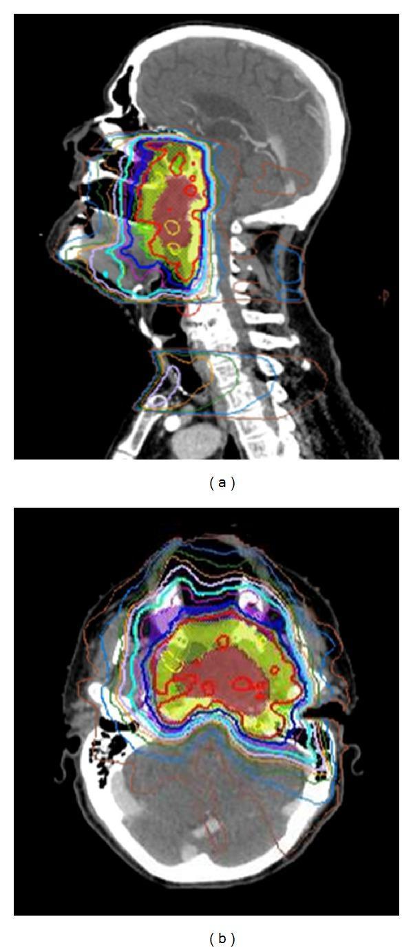
This diagnostic image displays a radiotherapy treatment plan for locally advanced nasopharyngeal cancer using Intensity-Modulated Radiation Therapy (IMRT). The visual consists of two panels: (a) a sagittal CT view and (b) an axial CT view of the head and neck. Overlaid on the anatomical structures are color-coded isodose lines representing radiation dose distribution. The highest dose regions (target volumes) are indicated by red and yellow areas, concentrated around the nasopharynx, skull base, and clivus. A sharp dose gradient is visible as the colors transition through green, blue, and cyan, reflecting rapid dose fall-off. This planning demonstrates the precision of IMRT in conforming high-dose radiation to the primary tumor while sparing adjacent critical 'organs at risk' (OARs), including the brainstem, spinal cord, and temporal lobes. The images highlight the clinical importance of high-resolution computerized planning and daily alignment (such as CBCT) to ensure target coverage and minimize toxicity to neuro-anatomical structures in head and neck squamous cell carcinoma (HNSCC) treatment.

This composite diagnostic and treatment planning image shows sagittal views of the head and neck, illustrating radiation therapy (RT) workflows for head and neck cancer (HNC). Panel A displays a baseline planning CT scan. Panels B and C show a co-registered T1-weighted MRI with an orange colormap; Panel C specifically highlights the delineated left hippocampus (blue contour) and the hippocampal planning organ-at-risk volume (PRV) (pink contour). Panels D, E, and F illustrate three different radiotherapy strategies overlaid on CT images: (D) standard clinical IMRT, (E) Hippocampal-Sparing Radiotherapy (HSRT), and (F) Brain-Sparing Radiotherapy (BSRT). The Planning Target Volume (PTV) is visualized in purple. Color-coded isodose lines represent dose distributions: 10 Gy (red), 20 Gy (blue), 30 Gy (yellow), and 61.75 Gy (green). The comparison highlights how HSRT and BSRT modify dose distribution to reduce radiation exposure to the hippocampal region and surrounding neural tissues compared to standard clinical protocols, aiming to preserve neurocognitive function.
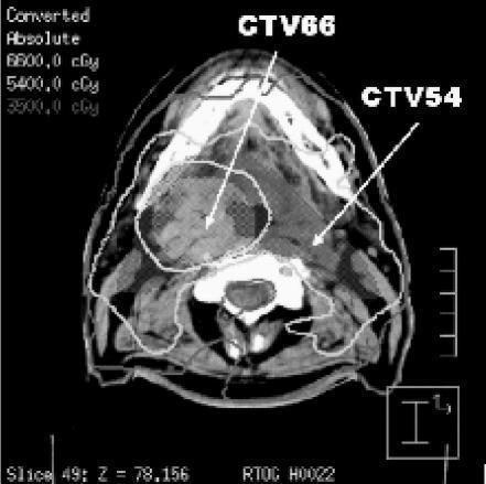
This diagnostic image is an axial computed tomography (CT) scan of the head and neck region, displaying an Intensity Modulated Radiation Therapy (IMRT) treatment plan. The image illustrates radiotherapy dose distribution through overlaid isodose lines and clinical target volumes (CTVs). The primary high-dose region, labeled CTV66, is an irregularly shaped area on the patient's right side, encompassed by the 6600.0 cGy (66 Gy) isodose line. A secondary target, labeled CTV54, represents a lower-dose volume situated lower in the neck, encompassed by the 5400.0 cGy (54 Gy) isodose line. A broader 3500.0 cGy (35 Gy) isodose line extends peripherally, demonstrating the dose fall-off toward surrounding healthy tissues. Key anatomical landmarks visible include the cervical vertebrae, mandible, and soft tissue structures of the neck. This image serves as an educational tool for understanding radiotherapy planning conformality, target volume delineation, and the spatial relationship between prescribed dose levels and cross-sectional anatomy in head and neck oncology.
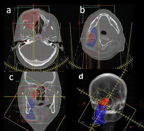
This set of diagnostic images illustrates radiation therapy planning for a head and neck malignancy using Intensity-Modulated Radiotherapy (IMRT). Panels (a) and (b) are axial CT slices showing the primary tumor volume (red mesh) in the maxillary/sinonasal region and the metastatic neck lymph node area (blue mesh) at an inferior level. Panel (c) provides a coronal CT reconstruction, demonstrating the vertical relationship between the superior primary lesion and the inferior nodal chain. Panel (d) displays a 'Beam’s Eye View' (BEV) of the treatment plan, visualizing the spatial orientation and field shaping for the target volumes. Superimposed on the CT images are multicolored isodose lines, with a prominent blue line representing the 95% isodose boundary. The high conformity of these lines around the red and blue target volumes highlights the precision of IMRT in delivering curative doses to the Gross Tumor Volume (GTV) while sparing adjacent critical structures in the head and neck. This visual material is intended for oncology education, focusing on radiotherapy contouring and dose distribution.
"head and neck cancer" AND "intensity modulated radiotherapy"
1. External Beam Radiotherapy (EBRT) - The Basic Concept
- Simulation - The patient is immobilized (a thermoplastic mask is used for the head and neck), reference points are marked with lasers/x-ray markers, and a planning CT scan is taken.
- Treatment Planning - The radiation oncologist outlines the tumor and nearby critical structures (spinal cord, salivary glands, optic nerves, brainstem) on the CT images. Three target volumes are defined:
- GTV (Gross Tumor Volume) - the visible/palpable tumor
- CTV (Clinical Target Volume) - GTV plus areas at risk of microscopic spread (e.g., draining lymphatics)
- PTV (Planning Target Volume) - CTV plus a margin to account for daily setup variation and patient motion
- Verification - Before treatment starts, imaging (portal films, orthogonal x-rays) confirms the patient is positioned exactly as planned.
- Dose Delivery - Delivered via a linear accelerator (LINAC), which produces a beam shaped by jaws or a multileaf collimator (MLC) - a device with many metal leaves that block or shape the beam (this replaced older lead blocks).
- Quality Assurance - Ongoing checks that the machine and plan are performing accurately.
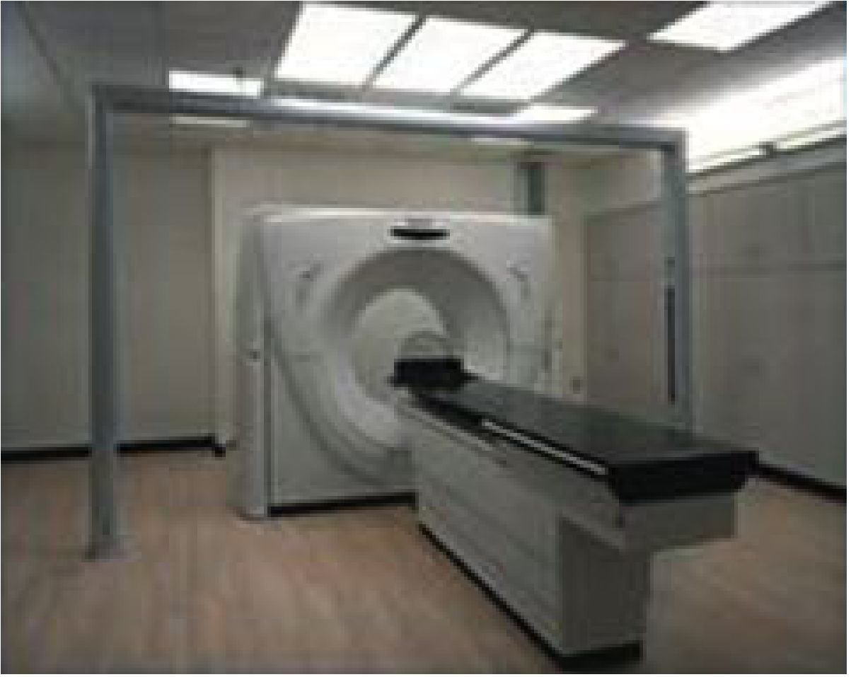
2. 3D Conformal Radiotherapy (3D-CRT)
- Uses 3D CT-based planning so the radiation oncologist can see the tumor and organs at risk in three dimensions, not just on a flat x-ray.
- Multiple beams are shaped (using the MLC) to conform to the 3D shape of the tumor from each beam angle, sparing more normal tissue than old 2D techniques.
- Classic technique for laryngeal cancer: opposed lateral fields matched to an anterior low-neck field (the "three-field technique"), using a "half-beam" setup to avoid overlapping the spinal cord.
- Limitation: beam intensity across each field is still relatively uniform ("static" fields) - it cannot create the complex, non-uniform dose "sculpting" that IMRT can.
3. Intensity-Modulated Radiotherapy (IMRT)
- Head and neck anatomy is crowded with critical structures (parotid/salivary glands, spinal cord, brainstem, optic nerves, esophagus) sitting very close to the tumor - IMRT's ability to "bend" dose around these structures is especially valuable here.
- Uses inverse treatment planning: the planner specifies desired doses to tumor and dose limits to organs at risk, and computer software works backward to calculate the beam pattern.
- Allows a simultaneous integrated boost (SIB) - delivering a higher dose to gross tumor and a lower dose to at-risk nodal areas in the same treatment session, rather than sequential fields.
- Major benefit: parotid gland sparing, which reduces xerostomia (dry mouth) - proven in the landmark PARSPORT trial, which showed IMRT significantly reduced xerostomia compared to conventional RT in pharyngeal cancers.
- Drawback: takes considerably more planning time/expertise than 3D-CRT, and poor planning has been linked to local treatment failures.
- A newer variant, Volumetric Modulated Arc Therapy (VMAT), delivers IMRT-style modulation while the machine rotates continuously around the patient - cutting treatment time from ~20-25 minutes (standard IMRT) to just 3-5 minutes, with even better organ-at-risk sparing and theoretically lower risk of secondary cancers.
4. Image-Guided Radiotherapy (IGRT)
- Because IMRT plans have very steep dose gradients (high dose right next to low dose), even small daily positioning errors can cause the tumor to be underdosed or a critical organ to be overdosed.
- IGRT solves this by taking imaging (e.g., cone-beam CT, portal imaging) immediately before or during each treatment session to verify and, if needed, adjust the patient's position/target location in real time - rather than relying only on the initial simulation setup.
- In the textbook's own words regarding early glottic cancer outcomes: better results with modern techniques come from combining accurate dose delivery with "image-guided verification for accurate daily reproducibility and dosimetry."
- The combination is often referred to as IG-IMRT, considered a current standard of care in many centers for HNC, since it lets clinicians exploit IMRT's tight conformality safely.
Quick Comparison Table
| Modality | Core Idea | Key Advantage | Key Limitation |
|---|---|---|---|
| EBRT (general) | Radiation from an external source (LINAC) | Foundation for all modern techniques | Precision depends on the specific technique used |
| 3D-CRT | 3D CT-based planning, shaped uniform beams | Better conformality than old 2D fields | Cannot vary intensity within a beam; less sparing of nearby organs |
| IMRT | Intensity-modulated, inverse-planned beams | Superior organ-at-risk sparing (e.g., parotids, less xerostomia); allows simultaneous boost | Complex, time-intensive planning; risk of error if poorly planned |
| IGRT | Imaging verification before/during each session | Corrects daily setup error, allows safe use of tight IMRT margins | Adds imaging dose/time; requires imaging equipment (CBCT) integrated with LINAC |
Recent evidence check
Radiotherapy in detail according to standard ENT textbook
1. Historical Background
- 1920s: Ionizing radiation first used for head and neck cancer, via external beam or interstitial rods (radium implants).
- Henri Coutard popularized protracted radiotherapy, which for a time partially displaced surgery as primary treatment for H&N cancer.
- Early era (orthovoltage generators, radium implants) caused severe skin damage, poor cure rates, and many complications.
- 1950s: The modern era began with the linear accelerator and telecobalt units, producing supervoltage radiation - far less skin toxicity.
- 1970s: Postoperative (adjuvant) radiotherapy became standard, shown to improve cure rates over surgery or RT alone.
- Late 1980s-1990s: 3D image-guided targeting, multileaf collimators, 3D-CRT, and finally IMRT emerged - progressively improving tumor dose conformality while sparing normal tissue.
- Today, RT alone or combined with cisplatin-based chemotherapy remains a mainstay of treatment for many head and neck cancers worldwide.
2. Radiobiology - How Radiation Kills Tumor Cells
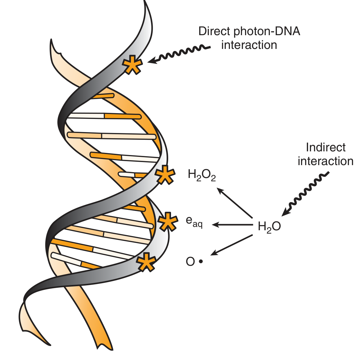
- DNA is the critical target. Radiation is called "ionizing" because it must ionize atoms to cause damage.
- Direct effect: radiation is absorbed directly by DNA, ionizing its atoms (relatively rare).
- Indirect effect (more common): radiation ionizes surrounding water molecules, generating free radicals (hydroxyl radicals, peroxide, hydrated electrons) that then damage DNA.
- Both mechanisms cause strand breaks in DNA. Single-strand breaks are easily repaired using the opposite strand as template. Double-strand breaks are the most important lesion - these cause mutation or, more importantly, cell killing.
- Other mechanisms of cell death: apoptosis, cell-cycle arrest, and mitotic death/catastrophe.
- Radiation triggers arrest, usually at the G1 and G2 checkpoints.
- Normal cells and cancer cells retaining functional p53 arrest in G1 (p53-mediated).
- Cells with p53 loss/mutation cannot arrest in G1 but can still arrest in G2; when they re-enter the cycle, some fail cytokinesis (forming multinucleated giant cells) or undergo mitotic catastrophe.
- States that rapidly proliferating cells are more radiosensitive than slowly proliferating ones.
- This is only partly true - many slowly proliferating normal tissues (e.g., kidney) are highly radiosensitive but express injury late. Similarly, some rapidly dividing tumors (e.g., glioblastoma) can be quite radioresistant.
- Tumor regression depends on more than direct cell death - also on stromal content, rate of cell death, and clearance of inactivated cells.
- Plotting surviving fraction (log scale) against dose (linear scale) produces a curve with an initial shoulder region (repairable damage) followed by a straight-line portion at higher doses.
- The clinically most influential model is the linear-quadratic (LQ) model, describing cell killing as having both a linear (αD) and a quadratic (βD²) dependence on dose - this underlies modern fractionation calculations (the α/β ratio).
3. Fractionation - Why Radiation Is Given in Multiple Small Doses
- Conventional fractionation: ~2 Gy/day, once daily, 5 days/week, to a total of 60-70 Gy.
- Hyperfractionation: Multiple smaller fractions per day (e.g., 1.1-1.2 Gy/fraction, twice daily) to a higher total dose (74-80 Gy) over the same overall treatment time. Rationale: late-responding normal tissues are more sensitive to fraction size than tumors are, so shrinking fraction size allows a higher cumulative dose without increasing late morbidity. Trials showed improved locoregional control (8-20% absolute benefit) and in some cases improved overall survival, at the cost of somewhat greater acute toxicity.
- Accelerated fractionation: Larger daily doses given to shorten overall treatment time, aiming to overcome tumor repopulation during therapy (a documented cause of treatment failure with prolonged treatment courses). Results across trials have been inconsistent for survival benefit, and added mucosal toxicity is a concern.
4. Treatment Techniques (Brief Recap)
- External Beam RT (EBRT): delivered via linear accelerator; workflow = simulation → planning (GTV/CTV/PTV delineation) → verification → delivery → quality assurance.
- 3D-CRT: CT-based 3D planning with shaped, largely uniform beams.
- IMRT/VMAT: intensity-modulated, inverse-planned beams for superior sparing of parotids, spinal cord, brainstem; VMAT delivers this via continuous gantry rotation, cutting treatment time dramatically.
- IGRT: imaging (e.g., cone-beam CT) immediately before/during treatment to verify positioning given IMRT's steep dose gradients.
- Brachytherapy: sealed radioactive sources placed directly into/near tumor (e.g., base of tongue) for rapid dose fall-off; can be low-dose-rate (catheter-based) or remote afterloading.
5. Indications - When Is RT Used?
- Definitive (curative) RT: primary treatment for early-stage disease (e.g., T1-T2 glottic cancer) where organ preservation and cure rates rival surgery, often with fewer functional deficits.
- Postoperative/Adjuvant RT (PORT): given after surgical resection when high-risk features are present - involved/positive margins, perineural invasion, bone/cartilage invasion, advanced T-stage (T3/T4), or advanced nodal disease (N2/N3), extracapsular extension. Landmark EORTC and RTOG trials showed that adding concurrent cisplatin chemotherapy to PORT further improves progression-free and overall survival in high-risk patients (particularly those with extracapsular extension or positive margins), at the cost of increased acute mucosal toxicity.
- Concurrent Chemoradiation (CRT): standard of care for many locoregionally advanced, unresectable, or organ-preservation cases (e.g., advanced laryngeal cancer, where CRT allows larynx preservation instead of total laryngectomy).
- Palliative RT: for symptom control (pain, bleeding, obstruction) in incurable or metastatic disease, using shorter/hypofractionated courses.
6. Complications of Radiotherapy
- Skin reactions: erythema, desquamation - IMRT can worsen skin reaction due to multiple beam angles; avoiding bolus effect (no ointments/creams over the field) helps.
- Mucositis: radiation kills basal stem cells in mucosa, causing painful denuding of epithelium; begins 2-3 weeks into treatment; incidence higher with concurrent chemoradiation (up to 64% in some series). Managed with oral hygiene, dietary modification, topical anesthetics.
- Acute xerostomia: significant salivary loss begins around 10 Gy to salivary glands.
- Chronic xerostomia: doses >26 Gy can cause permanent salivary gland dysfunction; managed by sparing at least one parotid (and submandibular glands) during planning, and using saliva substitutes. Amifostine reduced acute xerostomia from 78% to 51% and chronic xerostomia at 12 months from 57% to 34% in a landmark trial, but has significant side effects/cost and is not widely used; benefit is less clear with concurrent chemoradiation.
- Hypothyroidism: occurs in 30-40% after RT to the neck; requires periodic thyroid function testing.
- Laryngeal edema/necrosis: mild-moderate edema in 15-25% of glottic cancer patients post-RT; severe edema/necrosis is rarer (<5%).
- Osteoradionecrosis (ORN) of the jaw: a severe late complication, occurring in 5-10% of patients after conventional RT (mandible most affected due to its unilateral blood supply vs. bilateral maxillary supply). Risk factors include tooth extraction in irradiated fields and hyperfractionated regimens (23% vs. 9% incidence vs conventional in one study). Prevention includes pre-RT dental assessment/extraction of nonrestorable teeth, minimizing high-dose mandibular volume, and good oral hygiene. Management ranges from conservative debridement/antibiotics to radical resection with microvascular reconstruction in severe cases. Hyperbaric oxygen (HBO) has theoretical benefit but a randomized trial showed no clear advantage over placebo.
Summary Table
| Aspect | Key Point |
|---|---|
| History | Coutard (1920s) → LINAC/telecobalt (1950s) → 3D-CRT (1980s) → IMRT (1990s) |
| Radiobiology | DNA double-strand breaks = key lethal lesion; p53-dependent G1 arrest; linear-quadratic model guides fractionation |
| Fractionation | Conventional (2 Gy/day) vs hyperfractionation (smaller, twice-daily) vs accelerated (larger, shorter course) |
| Indications | Definitive, postoperative/adjuvant (high-risk features), concurrent chemoradiation, palliative |
| Major complications | Mucositis, xerostomia, hypothyroidism, laryngeal edema, osteoradionecrosis |