
Create notes of regional block used in gynaecological procedures along with diagrams and anatomy and nerves targeted and procedures done...TAP block Pudenal nerve block paracervical block rectus sheath block
TAP block transversus abdominis plane anatomy layers
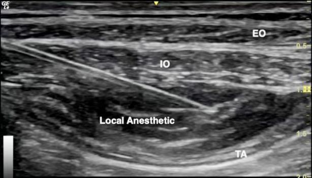
This diagnostic ultrasound image demonstrates a transversus abdominis plane (TAP) block procedure. The image depicts the layered anatomy of the lateral abdominal wall, showing three distinct muscle layers from superficial to deep: the external oblique (EO), internal oblique (IO), and transversus abdominis (TA) muscles. A hyperechoic, linear needle is visible entering from the left at an oblique angle, with its tip precisely positioned in the fascial plane between the IO and TA muscles. An anechoic to hypoechoic area is labeled 'Local Anesthetic,' showing the characteristic hydrodissection and separation of the IO and TA muscle layers as the fluid expands the potential space. This visual serves as a primary educational tool for regional anesthesia, illustrating real-time needle guidance and successful fascial plane infiltration for postoperative pain management. The image includes depth markers on the right and standard anatomical labels, making it suitable for training in ultrasound-guided nerve blocks.
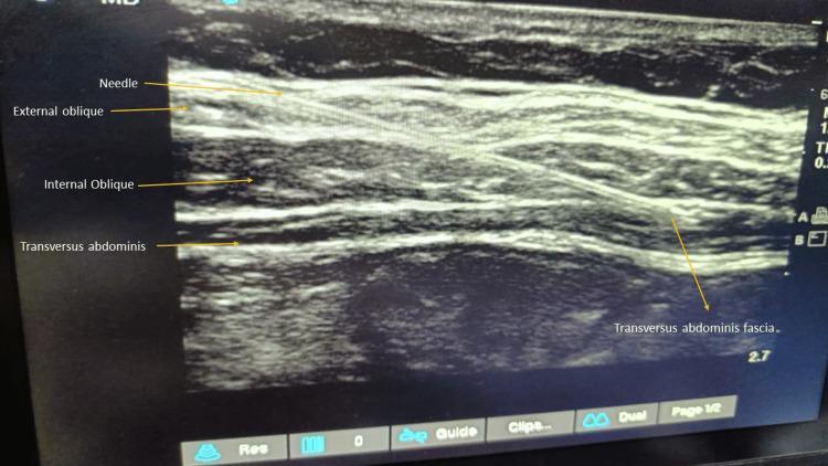
This diagnostic ultrasound image demonstrates the layered anatomy of the lateral abdominal wall, utilized for an ultrasound-guided transversus abdominis plane (TAP) block. The image clearly identifies three distinct muscle layers from superficial to deep: the external oblique, internal oblique, and transversus abdominis muscles. Each muscle layer appears as a relatively hypoechoic band separated by thin, bright hyperechoic fascial planes. A hyperechoic, linear needle is visualized using an 'in-plane' technique, traversing through the external and internal oblique muscles. The needle tip is positioned toward the fascial plane between the internal oblique and the transversus abdominis muscle, which is the target for local anesthetic deposition to block the thoracolumbar nerves (T7-L1). This imaging modality is essential in anesthesiology for providing regional analgesia following abdominal surgeries, ensuring accurate needle placement and reducing procedural complications.
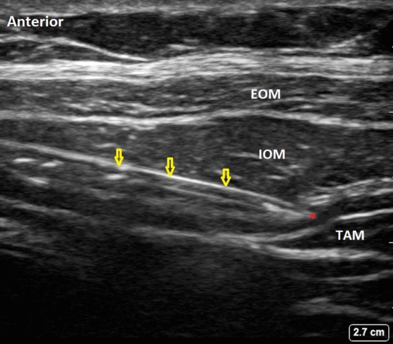
This diagnostic ultrasound image demonstrates the performance of a Transversus Abdominis Plane (TAP) block, a regional anesthesia technique. The image shows the layered anatomy of the lateral abdominal wall, with individual muscles clearly labeled: the External Oblique Muscle (EOM), Internal Oblique Muscle (IOM), and Transversus Abdominis Muscle (TAM). These muscle layers are separated by echogenic (bright) fascial planes. A highly echogenic, linear structure representing a block needle or catheter is identified by yellow arrows. It is positioned in an in-plane approach, traveling through the fascial plane located specifically between the IOM and TAM. A red asterisk marks the distal tip of the needle, where a small hypoechoic (dark) area indicates the initial administration of local anesthetic or saline (injectate), confirming correct placement within the target plane. The 'Anterior' orientation is noted on the left of the frame, and a scale bar in the bottom right indicates a depth of 2.7 cm. This image serves as an educational example of real-time needle guidance and anatomical identification for truncal nerve blocks.
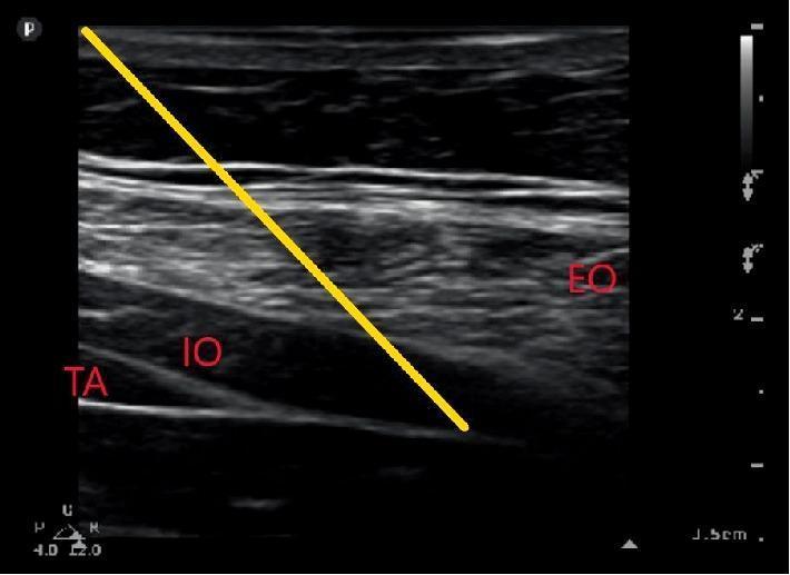
This diagnostic ultrasound image demonstrates the layered anatomy of the lateral abdominal wall for the purpose of guiding a transversus abdominis plane (TAP) or quadratus lumborum (QL) block. The image shows three distinct muscular layers: the superficial external oblique (EO), the intermediate internal oblique (IO), and the deep transversus abdominis (TA) muscle. These structures appear as hypoechoic bands separated by hyperechoic fascial planes. A prominent yellow line overlay indicates the simulated needle trajectory, originating from the top left and progressing diagonally toward the posterior aponeurosis of the transversus abdominis muscle. The clinical focus is on identifying the precise fascial interface for local anesthetic delivery to provide regional anesthesia. Landmarks such as the transversalis fascia and the relationship between muscle bellies and their aponeurotic extensions are clearly visible, serving as a pedagogical tool for ultrasound-guided regional anesthesia techniques in perioperative pain management.
pudendal nerve anatomy pelvis block
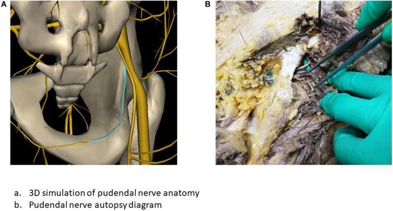
Educational comparison illustrating the anatomical localization of the pudendal nerve through two modalities: a 3D simulation (A) and a cadaveric autopsy dissection (B). Panel A presents an anatomical diagram using 3D bone reconstruction (gray-beige) of the pelvis, including the sacrum, ilium, and ischial spine. The pudendal nerve and its branching sacral plexus (S2–S4) are rendered in yellow. A light blue trace highlights the specific surgical path of the nerve as it travels through the greater sciatic foramen and along the inner aspect of the ischium toward the pudendal canal. Panel B shows a clinical photograph of a cadaveric dissection in the gluteal/perineal region. The image depicts the preserved anatomical tissues, showing muscular layers, yellowish adipose tissue, and connective fascia. A gloved hand uses metallic surgical forceps to isolate and demonstrate the physical path of the pudendal nerve among surrounding neurovascular structures. This comparison serves to correlate theoretical 3D digital mapping with real-world gross anatomy, specifically for planning surgical procedures such as pudendal nerve blocks or the implantation of neuromodulation electrodes.
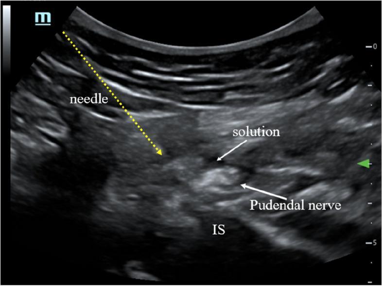
This ultrasound image demonstrates an ultrasound-guided pudendal nerve block or pulsed radiofrequency (PRF) treatment. The scan shows a cross-sectional view of the pelvic floor anatomy at the level of the ischial spine (IS). Key landmarks include the hyperechoic ischial spine (marked 'IS') providing a posterior bony boundary. The pudendal nerve is visualized as a small, mixed-echogenicity oval structure located superior and medial to the ischial spine. A needle trajectory is indicated by a yellow dotted line, originating from the top-left (in-plane approach) and terminating near the target nerve. A hypoechoic (dark) area labeled 'solution' is visible immediately adjacent to the pudendal nerve, representing the successful deposition of local anesthetic or therapeutic compound. This visual illustrates the precise placement required for regional anesthesia in the treatment of chronic pelvic pain or pudendal neuralgia, emphasizing the relationship between the nerve, the bony landmark of the ischial spine, and the therapeutic injectate.
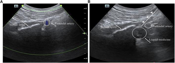
This educational medical visual consists of two ultrasound frames (A and B) demonstrating a guided pudendal nerve block procedure. Image A (pre-injection) shows the pelvic floor anatomy via a phased-array probe. Key landmarks include the ischial spine, visualized as a linear, hyperechoic (bright) band, and the pudendal artery, identified as a small, hypoechoic (dark) circular structure near the spine's tip. Image B (post-injection) illustrates the clinical application, featuring a needle trajectory marked by a white line with arrowheads. A larger hypoechoic area, labeled 'liquid medicine,' is visible adjacent to the pudendal artery, representing the local anesthetic spread around the pudendal nerve. The images serve as an anatomical guide for regional anesthesia, highlighting the spatial relationship between bony landmarks (ischial spine), vascular structures (pudendal artery), and the target nerve site for effective needle placement and anesthetic distribution in the management of post-operative pelvic or anorectal pain.
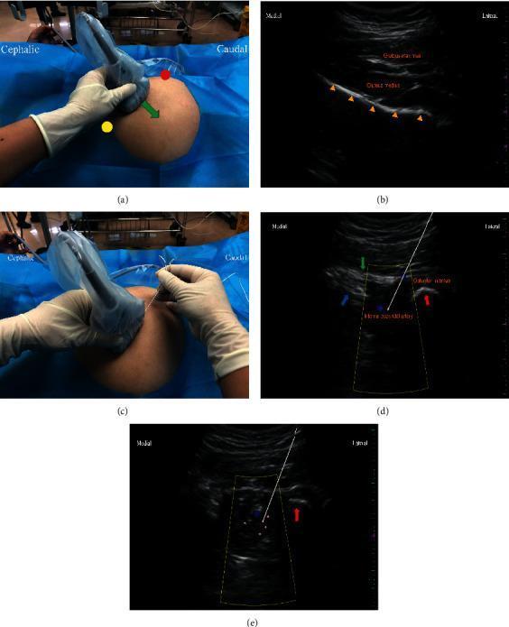
This composite figure illustrates the procedural steps and ultrasonographic anatomy for an ultrasound-guided pudendal nerve block (PNB) at the level of the ischial spine. Panel (a) shows the initial transducer placement between the greater trochanter and posterior superior iliac spine. Panel (b) is a gray-scale ultrasound image identifying the iliac bone as a continuous, hyperechoic specular reflector. Panel (c) depicts the lateral-to-medial in-plane needle insertion technique. Panel (d) shows the sonographic landmarks at the lesser sciatic notch, including the sacrospinous ligament (medial), sacrotuberous ligament (superficial), and ischial tuberosity (lateral). Color Doppler identifies the internal pudendal artery within the Alcock (pudendal) canal, situated in the acute angle between the coccygeus and internal obturator muscles. Panel (e) demonstrates the post-injection state, showing the hypoechoic spread of local anesthetic around the neurovascular bundle. This series serves as a clinical guide for anesthesiologists to achieve regional anesthesia for perineal procedures such as hemorrhoidectomy.
paracervical block cervix uterus anatomy injection
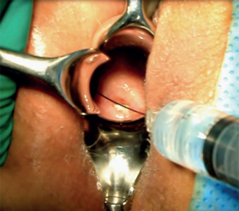
This clinical photograph demonstrates a gynecological interventional procedure with the patient in the lithotomy position. A metal speculum is utilized to retract the vaginal walls, providing clear visualization of the cervix (portio). The anterior lip of the cervix is secured with a surgical tenaculum to provide stabilization of the uterine anatomy. A syringe with a fine-gauge needle is visible in the foreground, performing a bilateral paracervical injection of local anesthetic (e.g., lidocaine). This paracervical block is a common clinical step to achieve regional anesthesia before invasive gynecological maneuvers such as cervical dilation or the insertion of an intracavitary brachytherapy applicator. The image highlights the precise anatomical positioning required for paracervical anesthesia, with the needle directed toward the lateral vaginal fornices where the sensory nerve supply to the cervix and lower uterus is located. The setup is performed under sterile conditions as part of a pre-planning or surgical phase in reproductive medicine or gynecological oncology.
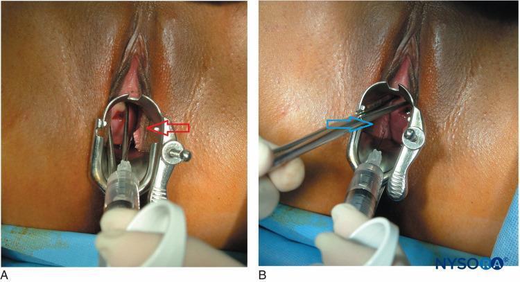
Two-panel clinical photograph (A and B) demonstrating the administration of a paracervical block in a gynecological setting. The images show a metal Grave's or Pederson speculum inserted into the vaginal vault to visualize the cervix and vaginal fornices. Panel A shows the injection of local anesthetic on the patient's left side (indicated by a red arrow) at the 4 o'clock position relative to the cervix. Panel B shows the injection on the patient's right side (indicated by a blue arrow) at the 8 o'clock position. A long, fine-gauge needle attached to a syringe is visible, being guided by a gloved clinician to the paracervical tissues. This procedure targets the Frankenhäuser plexus (uterovaginal plexus) to provide regional anesthesia for minor intrauterine procedures such as dilation and curettage (D&C). The anatomical landmarks visible include the labia majora, labia minora, vaginal canal, and the portio vaginalis of the cervix.
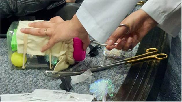
This clinical photograph captures a low-fidelity simulation of a Dilation and Evacuation (D&E) procedure, designed for medical education and physician training. The simulation model features a 'uterus' constructed from a clear plastic rectangular container, filled with various objects such as a yellow ball, green sponge, and iridescent mylar balls representing 'fetal parts.' The 'cervix' is simulated using a pink foam can holder secured to the container's opening, which is draped with beige fabric. A trainee's hands are visible, one stabilizing the model and the other operating a pair of silver-toned Bierer forceps to extract the contents through the simulated cervical canal. A pair of gold-handled surgical scissors lies on the surface nearby. This pedagogical tool is used to teach instrument handling, paracervical block techniques, and the tactile skills necessary for intrauterine procedures in obstetrics and gynecology. The setup illustrates an accessible, cost-effective method for clinical skills acquisition in reproductive health.
rectus sheath block anatomy posterior sheath umbilicus
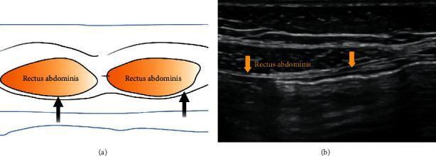
This dual-panel educational figure illustrates the Rectus Sheath Block (RSB), a regional anesthesia technique. Panel (a) is a schematic diagram showing a transverse cross-section of the anterior abdominal wall. It highlights the bilateral rectus abdominis muscles in orange, with black arrows indicating the target needle placement for local anesthetic infiltration into the potential space between the posterior rectus sheath and the muscle. Panel (b) shows a corresponding ultrasound image in the transverse plane lateral to the umbilicus. The rectus abdominis muscle is clearly visualized as a hypoechoic (darker) elliptical structure. Orange arrows point to the hyperechoic (brighter) fascial plane of the posterior rectus sheath, which serves as the injection point for the anesthetic solution. This visual is designed to teach medical professionals how to identify anatomical landmarks for ultrasound-guided abdominal wall blocks, focusing on the interface between the posterior rectus sheath and the rectus abdominis muscle.
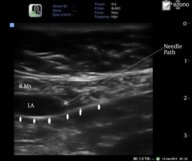
A transverse grayscale ultrasound image demonstrating a rectus sheath block procedure in the abdominal wall, located at or just above the umbilicus. The rectus abdominis muscle (RMs) is visualized as a relatively large, heterogeneous area in the superficial to mid-field. Below the muscle, a significant hypoechoic (dark) collection of local anesthetic (LA) is seen, illustrating hydrodissection between the muscle and the posterior rectus sheath. Small white arrows highlight the hyperechoic, linear posterior rectus sheath and fascia transversalis, which form the deep boundary of the injection site. An annotated white line indicates the 'Needle Path', demonstrating an in-plane approach from the lateral aspect toward the potential space between the muscle and the posterior sheath. This diagnostic image serves as an educational guide for regional anesthesia, highlighting essential sonographic landmarks and needle placement for effective blockade of the somatic sensory nerves (intercostal nerves T7-T11) within this anatomical plane.
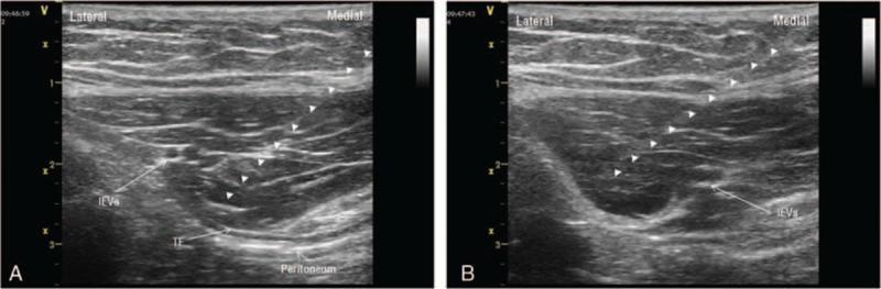
This diagnostic ultrasound display contains two frames (A and B) demonstrating an ultrasound-guided rectus sheath block (RSB). The images show the cross-sectional anatomy of the abdominal wall, specifically focusing on the posterior rectus sheath region. Key anatomical landmarks identified include the inferior epigastric vessels (IEVs), which appear as hypoechoic circular structures, the transversalis fascia (TF) visualized as a thin hyperechoic line, and the underlying peritoneum. Small white arrowheads indicate the needle trajectory using an in-plane technique. Frame A illustrates the needle tip positioned in the fascial plane between the medial aspect of the IEVs and the TF. Frame B shows the needle repositioned to the lateral aspect of the IEVs, with an evident hypoechoic fluid collection representing local anesthetic injectate separating the IEVs from the transversalis fascia. This image serves as a clinical guide for regional anesthesia, highlighting the precise needle placement required to achieve an effective superficial rectus sheath block while avoiding vascular or peritoneal injury.
Regional Blocks in Gynaecological Procedures
1. TRANSVERSUS ABDOMINIS PLANE (TAP) BLOCK
Anatomy
- External oblique muscle
- Internal oblique muscle
- Transversus abdominis muscle
Nerves Targeted
| Nerve | Root | Supplies |
|---|---|---|
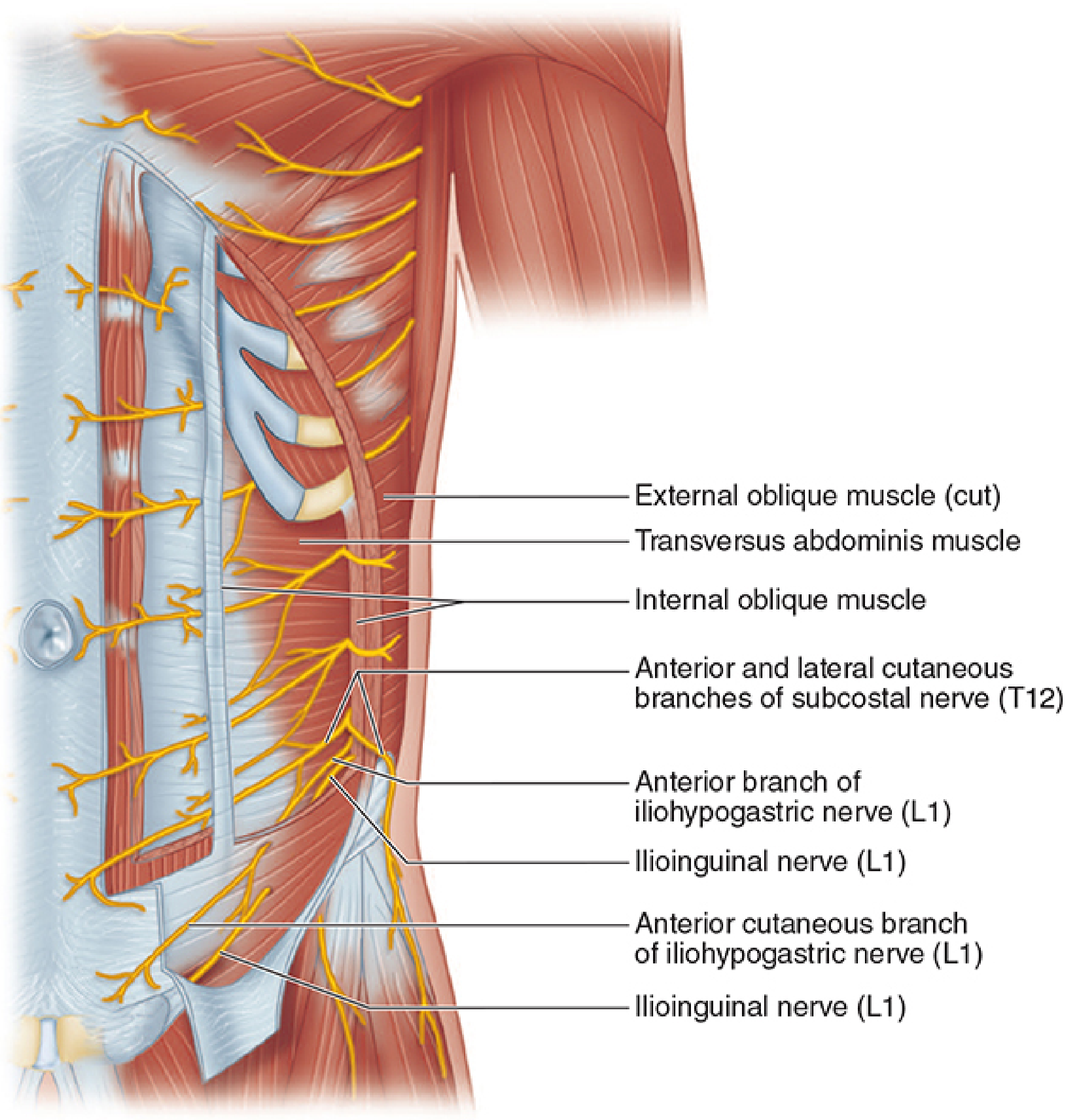
| Subcostal nerve | T12 | Lower abdominal wall |
| Iliohypogastric nerve | L1 | Suprapubic and inguinal region |
| Ilioinguinal nerve | L1 | Lower abdomen, upper medial thigh |
Ultrasound Appearance
Procedure (Ultrasound-Guided)
- Position: Patient supine (or lateral decubitus if preferred)
- Transducer: Linear array probe placed parallel to the inguinal ligament, just superior to the ASIS
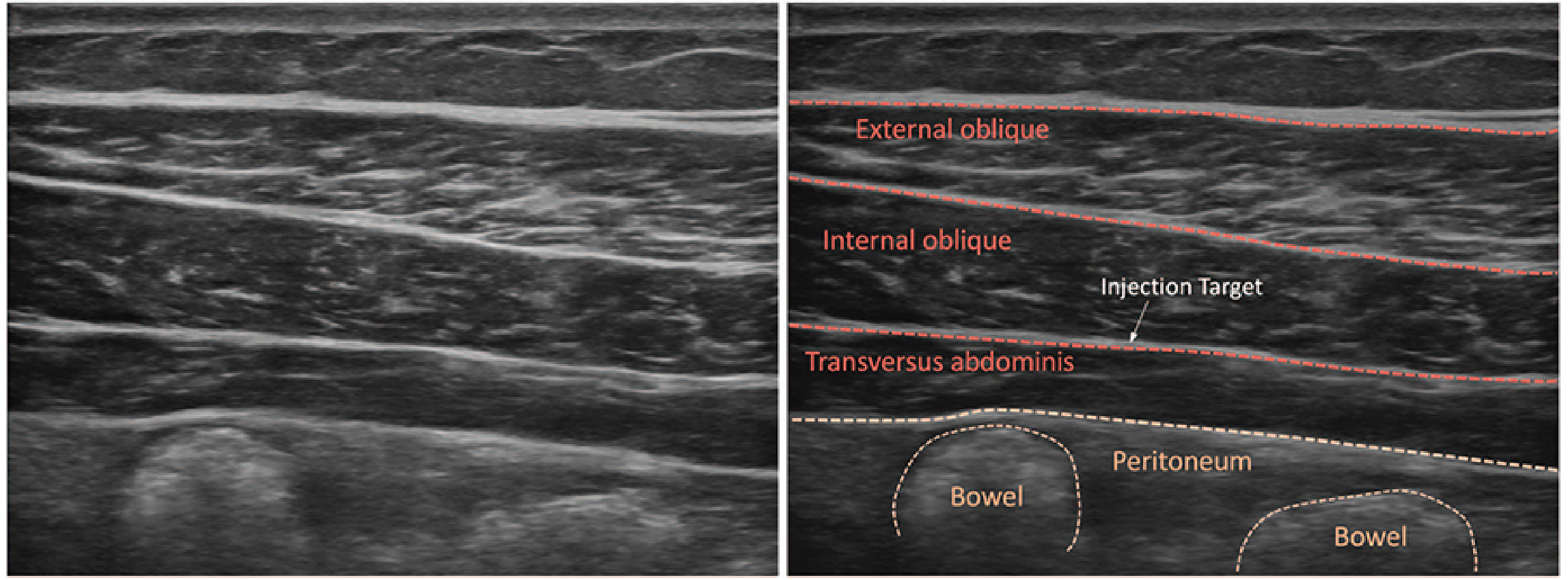
- Identification: Visualize all three muscle layers; identify the fascial plane between internal oblique (IO) and transversus abdominis (TA)
- Needle insertion: In-plane technique, lateral to medial; advance needle until tactile feedback of fascial planes is felt at the IO-TA interface
- Injection: ~30 mL of local anesthetic (e.g., 0.25-0.5% bupivacaine or ropivacaine); observe elliptical separation between fascial layers ("opening" of the plane)
- Aspiration before injection to rule out vascular placement
Gynaecological Indications
- Laparoscopic/laparotomic hysterectomy (postoperative analgesia)
- Caesarean section (bilateral TAP block)
- Laparoscopic salpingo-oophorectomy
- Laparoscopic myomectomy
- Endometrial ablation (open/laparoscopic approach)
- Major lower abdominal gynaecological surgery - component of enhanced recovery (ERAS) protocols
Complications
- Bowel perforation (risk reduced with USG guidance)
- Peritoneum violation
- Intravascular injection / local anaesthetic systemic toxicity (LAST)
- Block failure
2. PUDENDAL NERVE BLOCK
Anatomy
- Exits the pelvis through the greater sciatic foramen, inferior to the piriformis muscle
- Crosses the posterior aspect of the sacrospinous ligament / ischial spine
- Re-enters the pelvis through the lesser sciatic foramen
- Travels within Alcock's canal (pudendal canal) - a fascial sheath on the inner surface of the obturator internus muscle
- Divides into three terminal branches:
- Inferior rectal nerve - external anal sphincter, perianal skin
- Perineal nerve - labium majus/minus, vagina, perineal muscles, urethral sphincter
- Dorsal nerve of the clitoris - clitoris
Nerves Targeted
| Structure Blocked | Effect |
|---|---|
| Pudendal nerve (S2-S4) | Perineum, vulva, vaginal introitus, external anal sphincter, clitoris |
Approaches
A. Transvaginal Approach (most common in obstetrics)
- Patient in lithotomy position
- Iowa Trumpet (needle guide) inserted transvaginally
- The ischial spine is palpated through the lateral vaginal wall
- Needle advanced just medial and posterior to the ischial spine, through the sacrospinous ligament
- Aspirate to exclude vascular placement; inject 10 mL of local anesthetic (e.g., 1% lidocaine) on each side
B. Transperineal / Ultrasound-Guided Approach
- Ultrasound probe placed between the greater trochanter and posterior superior iliac spine
- Ischial spine identified as a bony hyperechoic landmark
- Internal pudendal artery located medial to the spine (using Doppler)
- Needle guided to the ischial spine region within Alcock's canal
Gynaecological / Obstetric Indications
- Vaginal delivery - second stage of labor analgesia
- Episiotomy - cutting and repair
- Forceps or vacuum extraction delivery (low pelvic station)
- Repair of perineal, vaginal, and cervical lacerations
- Vulvectomy (as part of multimodal analgesia)
- Chronic pelvic pain / pudendal neuralgia
- Anorectal procedures
Complications
- Hematoma (vaginal or ischiorectal)
- Retropubic/pelvic abscess (most feared - injection through non-sterile field)
- Intravascular injection (internal pudendal artery)
- Direct fetal injection (in obstetric setting - rare)
- High failure rate (~50% in some series)
- Impairs urge to push during second stage
Note: Pudendal block provides analgesia for the second stage of labor but is less effective than subarachnoid block with fentanyl and bupivacaine. - Miller's Anesthesia, 10e
3. PARACERVICAL BLOCK
Anatomy
- Uterine pain (visceral afferents) from T10-L1 travel via the sympathetic chain
- Cervical pain from S2-S4 via the pelvic splanchnic nerves
- Both pathways converge in the Frankenhauser plexus at the lateral fornix of the vagina
Nerves Targeted
| Plexus | Root | Supplies |
|---|---|---|
| Frankenhauser (uterovaginal) plexus | T10-L1 + S2-S4 | Cervix, lower uterus, upper vagina |
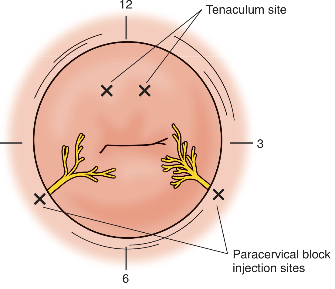
Procedure
- Patient in lithotomy position
- Insert bivalve speculum to visualize the cervix
- Apply tenaculum to anterior cervical lip for stabilization (nongravid cervix)
- Swab injection sites with antibacterial solution
- Using Iowa Trumpet (gravid) or direct visualization (nongravid):
- Insert 20-gauge needle no deeper than 0.5 cm into the submucosa at the cervicovaginal junction
- Gravid uterus: inject at 3 o'clock position first, then 9 o'clock
- Nongravid / early labor: nerves at 4 and 8 o'clock positions
- As labor progresses, nerve position migrates anteriorly
- Always aspirate before injecting to exclude vascular placement
- Inject 5-10 mL per side of local anesthetic (1% chloroprocaine preferred if repeated doses needed, to minimize fetal exposure; 1-2% lidocaine also used)
- Wait 3-5 minutes for onset
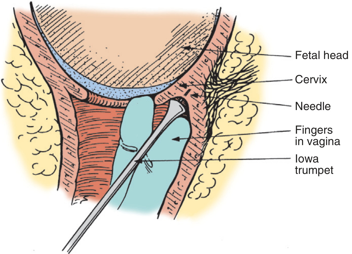
Gynaecological / Obstetric Indications
- First stage of labor analgesia (cervical dilation phase)
- Dilation and curettage (D&C)
- Dilation and evacuation (D&E)
- Intrauterine fetal demise (IUFD) labor analgesia
- Cervical conization (LEEP, laser)
- Hysteroscopy and endometrial ablation
- IUD insertion in anxious or stenotic cervix
- Induced abortion (first trimester)
Important Complications
| Complication | Notes |
|---|---|
| Fetal bradycardia | 25-35% incidence; due to rapid vascular uptake from highly vascular paracervical space |
| Direct fetal injection | Devastating; reason it is largely avoided in viable fetuses in the US |
| Maternal LA toxicity (LAST) | Highly vascular paracervical tissue |
| Vasovagal reaction | Common |
| Infection | Rare |
Recommendation: In viable fetuses, paracervical block is largely avoided in the United States. 1% to 2% chloroprocaine is preferred over lidocaine or mepivacaine if repeated doses are needed, as it is rapidly metabolized. - Creasy & Resnik's Maternal-Fetal Medicine
4. RECTUS SHEATH BLOCK
Anatomy
- Anterior layer - external oblique aponeurosis + anterior leaf of internal oblique
- Posterior layer (above arcuate line) - posterior leaf of internal oblique + transversus abdominis aponeurosis
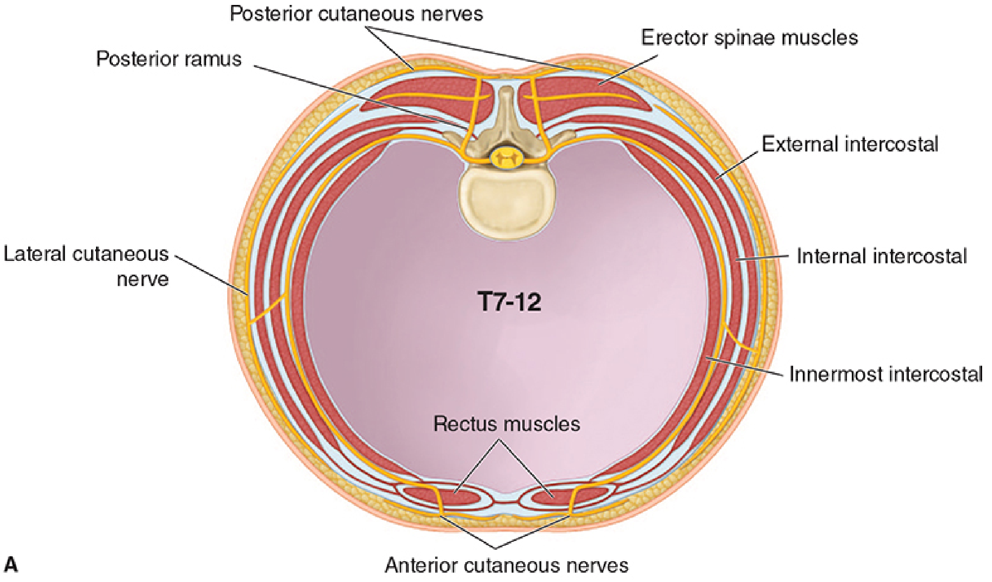
Nerves Targeted
| Nerve | Root | Area Supplied |
|---|---|---|
| Anterior cutaneous branches of intercostal nerves | T7-T12 | Anterior abdominal wall at and around the midline, from xiphoid to pubis |
- Coverage: Midline and paramedian anterior abdominal wall
- Does NOT provide analgesia for lateral abdominal wall or peritoneal/visceral pain
Ultrasound-Guided Procedure
- Patient supine
- Linear ultrasound probe placed transversely over the midline abdomen (at or near the umbilicus)
- Identify the linea alba as a hyperechoic midline structure
- Scan laterally to identify:
- Rectus abdominis - spindle-shaped hypoechoic muscle
- Anterior rectus sheath - hyperechoic layer superficial to muscle
- Posterior rectus sheath - hyperechoic layer deep to muscle
- Transversalis fascia and peritoneum deep to posterior sheath
- Block needle inserted from the lateral side of the transducer at a shallow angle
- Advance through the rectus muscle to its deep surface (posterior sheath interface)
- Inject 20 mL of local anesthetic per side to hydrodissect the rectus abdominis from the posterior sheath
Gynaecological Indications
- Midline laparotomy incisions (pfannenstiel or vertical midline)
- Total abdominal hysterectomy
- Myomectomy via midline incision
- Periumbilical port analgesia after laparoscopy
- Umbilical and paraumbilical hernia repair
- Trocar site analgesia for laparoscopic gynaecological procedures
Relationship to TAP Block
| Feature | TAP Block | Rectus Sheath Block |
|---|---|---|
| Target | IO-TA fascial plane | Posterior rectus sheath plane |
| Probe position | Lateral abdominal wall, above ASIS | Midline / paramedian |
| Nerves | T10-L1 (subcostal, ilioinguinal, iliohypogastric) | T7-T12 anterior cutaneous branches |
| Coverage | Lower lateral + lower anterior abdomen | Midline anterior abdomen |
| Incision type | Pfannenstiel, inguinal | Vertical midline, periumbilical |
Complications
- Peritoneal perforation / bowel injury (most serious - use USG guidance)
- Intravascular injection (inferior epigastric artery is in this plane - identify with Doppler)
- Bilateral rectus hematoma
- Incomplete block (nerves may have variable entry points)
SUMMARY COMPARISON TABLE
| Block | Nerves Targeted | Root Level | Coverage | Key Landmark | Volume (per side) | Main Gynaecological Use |
|---|---|---|---|---|---|---|
| TAP | Subcostal, ilioinguinal, iliohypogastric | T10-L1 | Lower anterior abdomen below umbilicus | IO-TA fascial plane above ASIS | 20-30 mL | Laparotomy, laparoscopy, Caesarean section |
| Pudendal | Pudendal nerve | S2-S4 | Perineum, vulva, vaginal introitus, clitoris | Ischial spine / Alcock's canal | 10 mL | Episiotomy, vaginal delivery, vulvectomy |
| Paracervical | Frankenhauser ganglion (uterovaginal plexus) | T10-L1 + S2-S4 | Cervix, lower uterus, upper vagina | Lateral vaginal fornix (4 & 8 o'clock) | 5-10 mL | D&C, D&E, first-stage labor, hysteroscopy |
| Rectus Sheath | Anterior cutaneous branches of intercostal nerves | T7-T12 | Anterior midline abdominal wall | Posterior rectus sheath | 20 mL | Midline laparotomy, periumbilical ports |
DRUG CHOICES (Common for All Blocks)
| Drug | Concentration | Onset | Duration | Notes |
|---|---|---|---|---|
| Bupivacaine | 0.25-0.5% | 15-20 min | 4-8 hours | Most commonly used; avoid >3 mg/kg |
| Ropivacaine | 0.2-0.5% | 10-15 min | 4-8 hours | Less cardiac toxicity than bupivacaine |
| Lidocaine | 1-2% | 5-10 min | 1-2 hours | Faster onset, shorter duration |
| Chloroprocaine | 1-2% | 3-5 min | 45-60 min | Preferred for paracervical block in obstetrics (rapid metabolism) |
Create notes of regional block used in gynaecological procedures along with diagrams and anatomy and nerves targeted and procedures done...TAP block Pudenal nerve block paracervical block rectus sheath block
TAP block transversus abdominis plane anatomy abdominal wall nerves
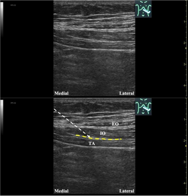
This diagnostic ultrasound image illustrates the musculoskeletal anatomy of the lateral abdominal wall, specifically for a Transversus Abdominis Plane (TAP) block or hydrodissection procedure. The image is presented in two panels: an unlabeled original view (top) and an annotated version (bottom). Three distinct muscle layers are visible with varying echogenicity: the superficial External Oblique (EO), the middle Internal Oblique (IO), and the deep Transversus Abdominis (TA). A dashed yellow line highlights the fascial plane—the TAP—situated between the IO and TA muscles. An overlaying white dashed line indicates a needle trajectory following an in-plane approach from a medial-to-lateral direction toward the target fascial space. Anatomical orientation markers 'Medial' and 'Lateral' are provided, and a depth scale in centimeters is visible on the right margin. This visual serves as an educational guide for ultrasound-guided regional anesthesia and pain management, demonstrating the precise localization of the ventral rami of spinal nerves for therapeutic intervention.
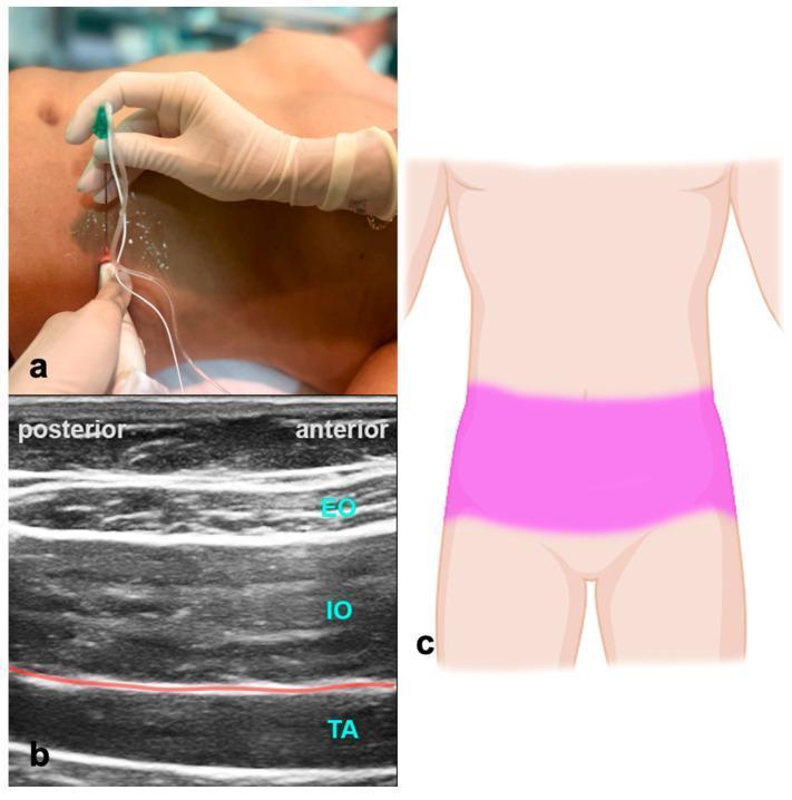
This composite educational image illustrates the Transversus Abdominis Plane (TAP) block procedure. Panel (a) shows a clinical photograph of the mid-axillary abdominal wall with an ultrasound transducer placed transversely and a needle inserted in-plane toward the lateral abdominal wall. Panel (b) is a high-frequency ultrasound image demonstrating the layered musculoskeletal anatomy of the abdominal wall. From superficial to deep, the external oblique (EO), internal oblique (IO), and transversus abdominis (TA) muscles are clearly visualized as hypoechoic structures separated by hyperechoic fascial planes. A red line indicates the target fascial plane for local anesthetic injection between the IO and TA muscles. Panel (c) is a schematic diagram showing the typical bilateral dermatomal spread of anesthesia across the lower abdomen (T10-L1) following a successful TAP block. This material is designed for teaching regional anesthesia techniques and ultrasound-guided nerve block landmarks.
This diagnostic ultrasound image demonstrates the layered anatomy of the lateral abdominal wall, utilized for an ultrasound-guided transversus abdominis plane (TAP) block. The image clearly identifies three distinct muscle layers from superficial to deep: the external oblique, internal oblique, and transversus abdominis muscles. Each muscle layer appears as a relatively hypoechoic band separated by thin, bright hyperechoic fascial planes. A hyperechoic, linear needle is visualized using an 'in-plane' technique, traversing through the external and internal oblique muscles. The needle tip is positioned toward the fascial plane between the internal oblique and the transversus abdominis muscle, which is the target for local anesthetic deposition to block the thoracolumbar nerves (T7-L1). This imaging modality is essential in anesthesiology for providing regional analgesia following abdominal surgeries, ensuring accurate needle placement and reducing procedural complications.
pudendal nerve anatomy pelvis ischial spine S2 S3 S4
Educational comparison illustrating the anatomical localization of the pudendal nerve through two modalities: a 3D simulation (A) and a cadaveric autopsy dissection (B). Panel A presents an anatomical diagram using 3D bone reconstruction (gray-beige) of the pelvis, including the sacrum, ilium, and ischial spine. The pudendal nerve and its branching sacral plexus (S2–S4) are rendered in yellow. A light blue trace highlights the specific surgical path of the nerve as it travels through the greater sciatic foramen and along the inner aspect of the ischium toward the pudendal canal. Panel B shows a clinical photograph of a cadaveric dissection in the gluteal/perineal region. The image depicts the preserved anatomical tissues, showing muscular layers, yellowish adipose tissue, and connective fascia. A gloved hand uses metallic surgical forceps to isolate and demonstrate the physical path of the pudendal nerve among surrounding neurovascular structures. This comparison serves to correlate theoretical 3D digital mapping with real-world gross anatomy, specifically for planning surgical procedures such as pudendal nerve blocks or the implantation of neuromodulation electrodes.
This ultrasound image demonstrates an ultrasound-guided pudendal nerve block or pulsed radiofrequency (PRF) treatment. The scan shows a cross-sectional view of the pelvic floor anatomy at the level of the ischial spine (IS). Key landmarks include the hyperechoic ischial spine (marked 'IS') providing a posterior bony boundary. The pudendal nerve is visualized as a small, mixed-echogenicity oval structure located superior and medial to the ischial spine. A needle trajectory is indicated by a yellow dotted line, originating from the top-left (in-plane approach) and terminating near the target nerve. A hypoechoic (dark) area labeled 'solution' is visible immediately adjacent to the pudendal nerve, representing the successful deposition of local anesthetic or therapeutic compound. This visual illustrates the precise placement required for regional anesthesia in the treatment of chronic pelvic pain or pudendal neuralgia, emphasizing the relationship between the nerve, the bony landmark of the ischial spine, and the therapeutic injectate.
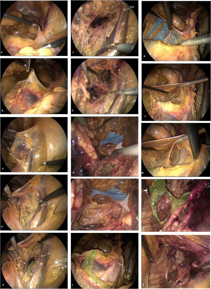
This composite of 15 laparoscopic photograms (labeled a-o) illustrates a step-by-step dissection of the retroperitoneal pelvic anatomy. The series follows a surgical progression starting from the sacral promontory and right psoas muscle (a-c), moving into the obturator fossa to identify the genitofemoral nerve (GFN), obturator nerve (ON), and lumbosacral trunk (LST) (d-f). Deeper dissection in panels g-i highlights the sciatic notch and floor of the pelvis, identifying the ischial spine, sacrospinous ligament (asterisk), iliococcygeus muscle (ICM), and pudendal neurovascular bundle. Panels j-m focus on the presacral space and superior hypogastric plexus (SHP), while n-o demonstrate the sacral nerve roots (S2-S4) and the inferior hypogastric plexus (IHP) with associated pelvic splanchnic nerves (PSN). High-contrast overlays—including blue for endopelvic fascia and green for neural plexuses—and white anatomical labels help distinguish complex neural, vascular, and muscular structures. This educational resource is designed to teach laparoscopic surgical landmarks and spatial relationships within the female pelvic retroperitoneum.
paracervical block injection cervix Frankenhäuser ganglion technique
Two-panel clinical photograph (A and B) demonstrating the administration of a paracervical block in a gynecological setting. The images show a metal Grave's or Pederson speculum inserted into the vaginal vault to visualize the cervix and vaginal fornices. Panel A shows the injection of local anesthetic on the patient's left side (indicated by a red arrow) at the 4 o'clock position relative to the cervix. Panel B shows the injection on the patient's right side (indicated by a blue arrow) at the 8 o'clock position. A long, fine-gauge needle attached to a syringe is visible, being guided by a gloved clinician to the paracervical tissues. This procedure targets the Frankenhäuser plexus (uterovaginal plexus) to provide regional anesthesia for minor intrauterine procedures such as dilation and curettage (D&C). The anatomical landmarks visible include the labia majora, labia minora, vaginal canal, and the portio vaginalis of the cervix.
This clinical photograph demonstrates a gynecological interventional procedure with the patient in the lithotomy position. A metal speculum is utilized to retract the vaginal walls, providing clear visualization of the cervix (portio). The anterior lip of the cervix is secured with a surgical tenaculum to provide stabilization of the uterine anatomy. A syringe with a fine-gauge needle is visible in the foreground, performing a bilateral paracervical injection of local anesthetic (e.g., lidocaine). This paracervical block is a common clinical step to achieve regional anesthesia before invasive gynecological maneuvers such as cervical dilation or the insertion of an intracavitary brachytherapy applicator. The image highlights the precise anatomical positioning required for paracervical anesthesia, with the needle directed toward the lateral vaginal fornices where the sensory nerve supply to the cervix and lower uterus is located. The setup is performed under sterile conditions as part of a pre-planning or surgical phase in reproductive medicine or gynecological oncology.
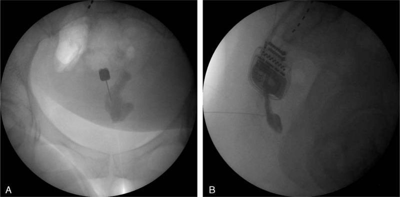
This diagnostic image displays dual fluoroscopic views (A: Anteroposterior; B: Lateral) of a ganglion impar block procedure. In Panel A, the pelvic bones and sacrococcygeal region are visible with a 22-gauge block needle inserted midline via a transsacrococcygeal approach. Following the injection of contrast media into the retroperitoneal space, an irregular radiopaque spread is noted at the needle tip. Panel B shows the lateral perspective, identifying the needle piercing the dorsal sacrococcygeal ligament with the tip positioned anterior to the ventral sacrococcygeal ligament. The contrast distribution exhibits a characteristic 'apostrophe' appearance, confirming appropriate needle placement for sympathetic block or neurolysis. Also visible in the upper field of both images is a previously implanted spinal cord stimulator (SCS) pulse generator and leads. This imagery illustrates the interventional pain management technique for treating chronic coccydynia and sympathetically maintained pelvic pain.
rectus sheath block posterior sheath intercostal nerve T7-T12 ultrasound
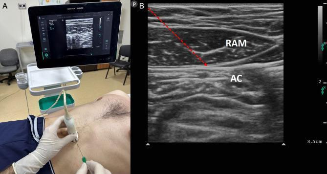
This dual-panel image demonstrates the clinical and sonographic components of a rectus sheath block (RSB), a regional anesthesia technique targeting T7-T12 spinal nerve endings. Panel A is a clinical photograph showing a patient in the supine position for a mid-abdominal intervention. A clinician, wearing sterile gloves, is performing the procedure using a high-frequency linear ultrasound probe placed in a transverse orientation over the rectus abdominis muscle. A block needle is visible being inserted in-plane toward the target site. An ultrasound monitor in the background displays the real-time procedural imaging. Panel B is a corresponding musculoskeletal ultrasound image (sonogram) labeling the relevant anatomy. The rectus abdominis muscle (RAM) is identified as a hypoechoic, spindle-shaped structure with internal fibrillar striations. Deep to the RAM is the abdominal cavity (AC), appearing heterogeneous and hyperechoic due to bowel interfaces. A red dashed arrow indicates the needle's trajectory, targeting the potential space between the posterior aspect of the rectus muscle and the posterior rectus sheath to deliver local anesthetic.
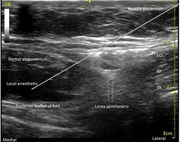
An ultrasound diagnostic image demonstrating a transversus abdominis plane (TAP) and rectus sheath block procedure. The image displays the anterolateral abdominal wall musculature in cross-section. On the right (lateral aspect), three distinct muscle layers are visible: the external oblique (EO), internal oblique (IO), and transversus abdominis (TA) muscles, separated by hyperechoic fascial planes. Progressing medially, the linea semilunaris marks the transition where these muscles meet the rectus abdominis muscle. A white line indicates the 'Needle projection,' showing an in-plane approach from lateral to medial. The needle tip terminates between the rectus abdominis muscle and the hyperechoic posterior leaflet of the rectus abdominis sheath (RAS). A significant hypoechoic (dark) area is labeled 'Local anesthetic,' illustrating the successful hydrodissection and spread of injectate within the posterior rectus sheath plane. This visual serves as a clinical guide for regional anesthesia, highlighting essential landmarks for ultrasound-guided nerve blocks of the T7-T12 intercostal nerves.
A transverse grayscale ultrasound image demonstrating a rectus sheath block procedure in the abdominal wall, located at or just above the umbilicus. The rectus abdominis muscle (RMs) is visualized as a relatively large, heterogeneous area in the superficial to mid-field. Below the muscle, a significant hypoechoic (dark) collection of local anesthetic (LA) is seen, illustrating hydrodissection between the muscle and the posterior rectus sheath. Small white arrows highlight the hyperechoic, linear posterior rectus sheath and fascia transversalis, which form the deep boundary of the injection site. An annotated white line indicates the 'Needle Path', demonstrating an in-plane approach from the lateral aspect toward the potential space between the muscle and the posterior sheath. This diagnostic image serves as an educational guide for regional anesthesia, highlighting essential sonographic landmarks and needle placement for effective blockade of the somatic sensory nerves (intercostal nerves T7-T11) within this anatomical plane.
🔵 Regional Blocks in Gynaecological Procedures
Complete Study Notes with Anatomy, Nerves & Diagrams
1. TRANSVERSUS ABDOMINIS PLANE (TAP) BLOCK
Anatomy
| Layer | Muscle |
|---|---|
| 1st (superficial) | External oblique |
| 2nd (middle) | Internal oblique |
| 3rd (deepest) | Transversus abdominis |
Nerves Targeted
| Nerve | Root | Region Supplied |
|---|---|---|
| Subcostal nerve | T12 | Lower anterior abdominal wall |
| Iliohypogastric nerve | L1 | Suprapubic and inguinal region |
| Ilioinguinal nerve | L1 | Lower abdomen, upper medial thigh, mons pubis |
- Does NOT cover visceral/intraperitoneal pain
- Bilateral blocks required for midline procedures
Ultrasound-Guided Technique
- Position: Supine or lateral decubitus
- Probe: Linear array transducer (curvilinear in obese patients), placed parallel to the inguinal ligament, just superior to the ASIS
- Identify layers: Scan to see all three striated muscle layers (hypoechoic) separated by hyperechoic fascial planes
- Needle insertion: In-plane technique, inserted lateral to medial until the tip reaches the IO-TA interface. A tactile "pop" through the fascial plane is felt
- Injection: ~30 mL local anesthetic injected, observing elliptical separation (hydrodissection) between IO and TA fasciae
- Always aspirate before injection to exclude intravascular placement
Gynaecological Procedures
- Caesarean section (bilateral TAP) - component of ERAS protocols
- Total abdominal hysterectomy (TAH)
- Laparoscopic hysterectomy / salpingo-oophorectomy
- Laparoscopic myomectomy
- Ovarian cystectomy (open or laparoscopic)
- Pfannenstiel / lower midline incisions
- Endometrial ablation (open approach)
- Trocar-site analgesia for laparoscopy
Complications
| Complication | Notes |
|---|---|
| Bowel perforation | Most serious - minimized with USG |
| Peritoneal violation | Especially without ultrasound |
| LAST (local anaesthetic systemic toxicity) | Large volumes used bilaterally |
| Block failure | ~10-15%; supplement IV/local |
| Haematoma | Rare |
2. PUDENDAL NERVE BLOCK
Anatomy
- Exits pelvis through the greater sciatic foramen (inferior to piriformis)
- Crosses the posterior surface of the ischial spine / sacrospinous ligament
- Re-enters the pelvis through the lesser sciatic foramen
- Travels within Alcock's canal (pudendal canal) - a fascial sheath within the obturator internus fascia, on the lateral wall of the ischioanal fossa
- Accompanied throughout by the internal pudendal artery and vein
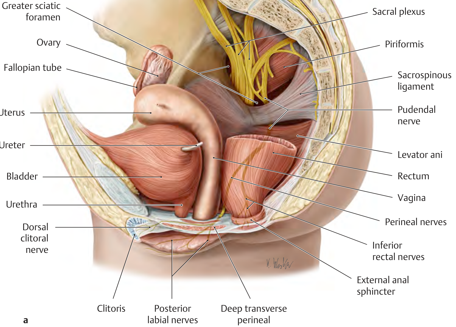
Terminal Branches
| Branch | Supplies |
|---|---|
| Inferior rectal nerve | External anal sphincter, perianal skin |
| Perineal nerve | Posterior labium majus/minus, vaginal introitus, perineal muscles, external urethral sphincter, posterior scrotum |
| Dorsal nerve of clitoris/penis | Clitoris, dorsum of penis |
Technique
A - Transvaginal Approach (standard in obstetrics)
- Patient in lithotomy position
- Insert Iowa Trumpet (needle guide) transvaginally using index and middle fingers as guides
- Palpate the ischial spine through the lateral vaginal wall
- Place the trumpet tip just medial and posterior to the ischial spine (1 cm above and lateral)
- Advance 20-gauge needle through the trumpet; depth limited to 1 cm through the mucosa
- Aspirate to exclude intravascular placement
- Inject 10 mL local anesthetic; repeat on the opposite side
B - Ultrasound-Guided Approach
- Linear probe placed between greater trochanter and posterior superior iliac spine
- Scan medially to identify the ischial spine as a hyperechoic bony landmark
- Locate the internal pudendal artery with colour Doppler (medial to the ischial spine)
- The pudendal nerve lies adjacent to the artery within Alcock's canal
- In-plane needle guidance; inject 10 mL local anesthetic around the neurovascular bundle
Bupivacaine is contraindicated in obstetric paracervical block but can be used for pudendal block in non-obstetric procedures with standard precautions.
Gynaecological / Obstetric Indications
- Second stage of labor analgesia (pushing phase)
- Episiotomy - incision and repair
- Forceps or vacuum-assisted delivery (low/outlet station)
- Repair of perineal, vaginal, labial, and cervical lacerations
- Vulvectomy (partial/radical)
- Bartholin gland surgery
- Vulvar biopsy / excision
- Chronic pudendal neuralgia / pelvic floor pain
- Anorectal surgery (haemorrhoidectomy, fistula repair)
Complications
| Complication | Notes |
|---|---|
| Pelvic/retropsoas abscess | Most feared; injection through non-sterile field |
| Ischiorectal / vaginal haematoma | Due to pudendal vessel puncture |
| LAST | Internal pudendal artery nearby |
| Direct fetal injection | If performed in late labor with dilated cervix |
| Block failure | ~50% failure rate reported; high inter-operator variability |
| Impairs urge to push | Motor component of pudendal nerve blocked |
"Although a pudendal nerve block provides some relief during second stage, it is not as effective as a subarachnoid block with fentanyl and bupivacaine." - Miller's Anesthesia, 10e
3. PARACERVICAL BLOCK
Anatomy
- Visceral afferents from the uterine body (T10-L1) via the sympathetic chain and superior hypogastric plexus
- Cervical afferents (S2-S4) via the pelvic splanchnic nerves and inferior hypogastric plexus
Nerves Targeted
| Structure | Root | Supplies |
|---|---|---|
| Frankenhauser plexus (uterovaginal plexus) | T10-L1 + S2-S4 | Uterine body, cervix, upper vagina |
Injection Sites (Clock Face of Cervix)
Technique
- Patient in lithotomy position
- Insert bivalve speculum; apply tenaculum to anterior lip of cervix (nongravid)
- Clean injection sites with antibacterial solution
- In labor (gravid): Use Iowa Trumpet guided by two fingers in the vagina
- Advance 20-gauge needle through the mucosa at the cervicovaginal junction
- Depth: maximum 0.5 cm into the submucosa (no deeper)
- Nongravid / early labor: Inject at 4 and 8 o'clock
- Active labor: Position migrates anteriorly with progressive dilation
- Aspirate before every injection (highly vascular area)
- Inject 5-10 mL per side; may inject in 2-3 divided aliquots around the nerve location
- Monitor fetal heart rate after injection (gravid patient)
Drug Choice
| Drug | Dose | Notes |
|---|---|---|
| Chloroprocaine 1-2% | 5-10 mL/side | Preferred if repeated doses needed; rapidly metabolized, minimizes fetal exposure |
| Lidocaine 1% | 5-10 mL/side | Max 70 mg/side (1 mg/kg); standard choice |
| Bupivacaine | CONTRAINDICATED | Increased cardiotoxicity risk in gravid patient |
- Lidocaine: 300 mg total (4.5 mg/kg); do not repeat < 2 hours
- Chloroprocaine: 120 mg total; do not repeat < 1 hour
Gynaecological / Obstetric Indications
| Setting | Indication |
|---|---|
| Obstetric | First-stage labor analgesia (cervical dilation 5-9 cm) |
| Obstetric (non-viable) | Intrauterine fetal demise (IUFD) labor analgesia |
| Gynaecology | Dilation and curettage (D&C) |
| Gynaecology | Dilation and evacuation (D&E) |
| Gynaecology | Induced abortion (first trimester) |
| Gynaecology | LEEP / laser cervical conization |
| Gynaecology | Hysteroscopy and endometrial ablation |
| Gynaecology | IUD insertion (difficult/stenotic cervix) |
| Gynaecology | Cervical biopsy |
Complications
| Complication | Details |
|---|---|
| Fetal bradycardia | 25-35% incidence; due to rapid systemic absorption from vascular paracervical space; usually transient |
| Direct fetal injection | Devastating complication; causes fetal cardiac arrest |
| Maternal LAST | Highly vascular area - rapid absorption |
| Vasovagal reaction | Common; position flat before and after |
| Infection | Rare |
| Failed block | Frequent in heavily dilated or progressed labor |
"Paracervical block was a popular form of anesthesia for the first stage of labor until it was implicated in several fetal deaths and was shown to be associated with fetal bradycardia in 25% to 35% of cases." - Creasy & Resnik's Maternal-Fetal Medicine
In the United States, paracervical block for viable fetuses is largely avoided. It remains in use for D&C, D&E, IUFD, and non-obstetric gynaecological procedures.
4. RECTUS SHEATH BLOCK (RSB)
Anatomy
- Anterior rectus sheath - external oblique aponeurosis + anterior layer of internal oblique
- Posterior rectus sheath (above arcuate line only) - posterior layer of internal oblique + transversus abdominis aponeurosis
- Below the arcuate line (midway between umbilicus and pubis), all layers pass anteriorly; posterior sheath becomes thin transversalis fascia only
Nerves Targeted
| Nerve | Root | Area Supplied |
|---|---|---|
| Anterior cutaneous branches of intercostal nerves | T7-T12 | Midline anterior abdominal wall, from xiphisternum to pubic symphysis |
- Produces an elliptical midline block distribution
- Does NOT provide lateral abdominal wall analgesia
- Does NOT provide visceral or peritoneal analgesia
Ultrasound-Guided Technique
- Patient supine
- Linear ultrasound probe placed transversely over the midline abdomen (at the umbilical level or above)
- Identify the linea alba as a hyperechoic midline structure
- Scan laterally to identify:
- Rectus abdominis - spindle-shaped hypoechoic muscle
- Anterior rectus sheath - hyperechoic fascia superficial to muscle
- Posterior rectus sheath - hyperechoic fascia deep to muscle
- Transversalis fascia and peritoneum - deep to posterior sheath
- Needle enters from the lateral side at a shallow angle (to avoid deep injury)
- Advance through the rectus muscle to the deep surface - posterior sheath plane
- Inject 20 mL local anesthetic per side; watch for hydrodissection (fluid separating muscle from posterior sheath)
- Note: Identify and avoid the inferior epigastric vessels (use Doppler)
Gynaecological Indications
| Indication | Notes |
|---|---|
| Total abdominal hysterectomy (midline/pfannenstiel incision) | Bilateral RSB replaces thoracic epidural for midline incisions |
| Myomectomy (midline laparotomy) | Excellent midline coverage |
| Periumbilical laparoscopic port analgesia | Single-injection for camera port |
| Umbilical/paraumbilical hernia repair | Surgical anaesthesia for superficial procedures |
| Midline laparotomy for ovarian cancer staging | Bilateral continuous catheters for ERAS |
| Pfannenstiel incision supplementation | Complements TAP block for more complete coverage |
Comparison: TAP Block vs Rectus Sheath Block
| Feature | TAP Block | Rectus Sheath Block |
|---|---|---|
| Target plane | IO-TA fascial plane (lateral wall) | Posterior rectus sheath plane (midline) |
| Probe position | Lateral wall, superior to ASIS | Over rectus muscle, transverse midline |
| Nerves | Subcostal T12, ilioinguinal L1, iliohypogastric L1 | Anterior cutaneous branches T7-T12 |
| Coverage | Lower lateral + lower anterior abdomen | Anterior midline only (xiphoid to pubis) |
| Best for | Pfannenstiel, lower abdominal incisions | Vertical midline, periumbilical ports |
| Volume | 20-30 mL per side | 20 mL per side |
| Bilateral? | Yes for midline | Yes always |
Complications
| Complication | Notes |
|---|---|
| Bowel/peritoneal perforation | Most serious; use USG always |
| Inferior epigastric vessel injury | Identify with Doppler before injecting |
| Bilateral rectus haematoma | Rare; can be serious |
| Incomplete block | Nerves enter at variable sites |
| LA toxicity | Bilateral blocks - monitor cumulative dose |
MASTER COMPARISON TABLE
| Feature | TAP Block | Pudendal Block | Paracervical Block | Rectus Sheath Block |
|---|---|---|---|---|
| Nerve(s) | Subcostal T12, ilioinguinal L1, iliohypogastric L1 | Pudendal nerve S2-S4 | Frankenhauser plexus T10-L1 + S2-S4 | Intercostal T7-T12 anterior cutaneous |
| Plane / Target | IO-TA fascial plane | Ischial spine / Alcock's canal | Lateral vaginal fornix | Posterior rectus sheath |
| Coverage | Lower abdomen below umbilicus | Perineum, vulva, vaginal introitus, clitoris | Cervix, lower uterus, upper vagina | Midline anterior abdominal wall |
| Approach | Ultrasound-guided (lateral flank) | Transvaginal or USG-guided | Direct (vaginal/speculum) | Ultrasound-guided (transabdominal) |
| Volume | 20-30 mL/side | 10 mL/side | 5-10 mL/side | 20 mL/side |
| Drug | Bupivacaine 0.25-0.5% / Ropivacaine | Lidocaine 1% | Chloroprocaine 1-2% / Lidocaine 1% | Bupivacaine 0.25-0.5% |
| Position | Supine / lateral decubitus | Lithotomy | Lithotomy | Supine |
| Labour use | No | 2nd stage / delivery | 1st stage (cervical dilation) | No |
| Gynaecological use | TAH, CS, laparoscopy | Episiotomy, vulvectomy | D&C, hysteroscopy, LEEP | TAH, myomectomy, laparoscopy ports |
LOCAL ANAESTHETIC DRUG REFERENCE
| Drug | Concentration | Onset | Duration | Max Dose | Notes |
|---|---|---|---|---|---|
| Bupivacaine | 0.25-0.5% | 15-20 min | 4-8 hrs | 2 mg/kg (150 mg) | CONTRAINDICATED in obstetric paracervical block |
| Ropivacaine | 0.2-0.5% | 10-15 min | 4-8 hrs | 3 mg/kg | Less cardiac toxicity than bupivacaine |
| Lidocaine | 1-2% | 5-10 min | 1.5-2 hrs | 4.5 mg/kg (300 mg) | Add adrenaline to extend duration |
| Chloroprocaine | 1-2% | 3-5 min | 45-60 min | 120 mg | Preferred for paracervical block (rapid metabolism) |