

Need a proper notes of ift with diagram and each question is of 15 mrk and reference book should be BK nanda Clayton and low and reed
interferential therapy IFT electrode placement diagram
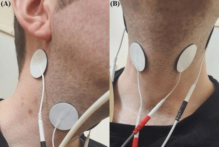
Clinical photograph in two views (A and B) demonstrating the electrode placement for Interferential Current (IFC) therapy, a neuromuscular electrical stimulation technique used in dysphagia rehabilitation. Image (A) provides a lateral (side) view of the neck, showing two circular, white surface electrodes adhered to the skin. One is positioned in the submental region near the angle of the mandible, and the second is placed inferiorly along the anterior border of the sternocleidomastoid muscle, targeting the superior laryngeal nerve pathway. Image (B) shows an anterior (front) view, illustrating the symmetrical placement of the electrodes on both sides of the laryngeal prominence. Thin, white lead wires with color-coded connectors (red and black) are attached to the electrodes, connecting to an external BTL-4000 Smart device. This setup is designed to stimulate pharyngeal and laryngeal muscles to improve swallowing function, specifically epiglottic inversion and hyoid bone movement, in patients with post-stroke dysphagia.
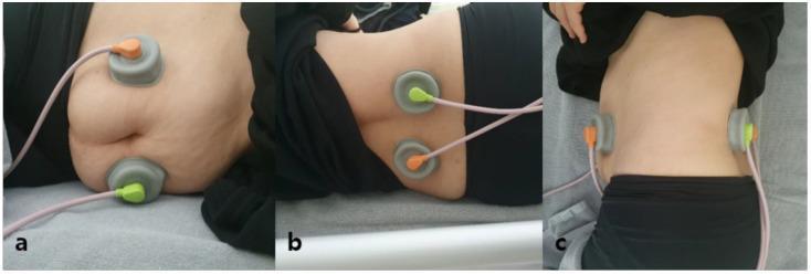
This composite of three clinical photographs illustrates the electrode placement for two-channel interferential current (IFC) therapy aimed at bowel stimulation. (a) Anterior view: Two circular grey electrodes with orange and green color-coded connectors are placed bilaterally on the anterior abdominal wall below the costal margin. (b) Posterior view: Two corresponding electrodes are positioned on the patient's back flanking the spine between the T12 and L4 vertebrae. (c) Lateral view: Provides a profile of the cross-sectional alignment, demonstrating how the electrodes are situated to create a crossing current path through the abdominal cavity. The patient is shown in a supine position on a medical table. Pink insulated wires connect each electrode to the IFC device. This procedural configuration is used in physical therapy and gastroenterology to modulate intestinal motility using a carrier frequency (e.g., 5 kHz) and beat frequency without inducing painful muscle contractions.
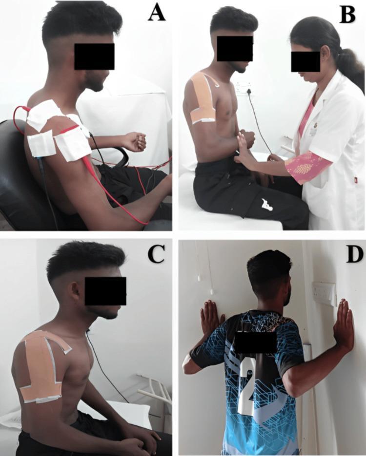
A multi-panel clinical photograph illustrating various stages of physiotherapy and rehabilitation for a shoulder injury. Panel A shows a seated patient receiving interferential therapy (IFT), with a four-pole electrode configuration using large white pads and red/black wires over the right shoulder and periscapular region for pain modulation. Panel B depicts a healthcare professional assisting the patient with isometric external rotation exercises; the patient's shoulder is stabilized with kinesiotherapy tape. Panel C focuses on specialized therapeutic taping, demonstrating an 'inverted J' application over the lateral and anterior deltoid aimed at increasing subacromial space. Panel D shows the patient performing active rehabilitation through wall push-ups in the scaption plane to improve scapular stability and muscle strength. The sequence represents a comprehensive orthopedic rehabilitation protocol ranging from passive pain management to active functional strengthening. The patient is a young adult male, and the setting is a clinical physiotherapy environment.
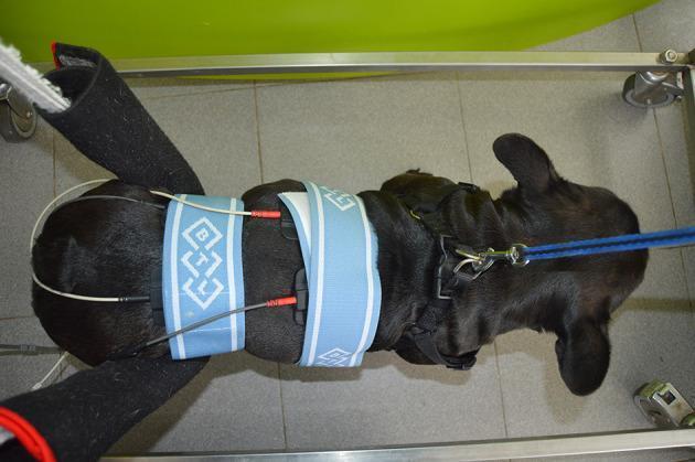
A clinical photograph taken from a dorsal view showing a patient (canine model) undergoing interferential electrical stimulation (IES) for pain management. The image demonstrates the precise electrode placement for dual-channel stimulation over the spinal column. Four rubber and carbon electrodes are secured in a quadripolar, crossed configuration (90-degree intersection) using two light blue elasticated bands. This arrangement is designed to deliver a modulated frequency at the site of spinal hyperesthesia. The patient is positioned in a postural standing stance supported by an underwater treadmill frame, which serves as a functional neurorehabilitation (FNR) device. Assistive features include a padded frontal support for the forelimbs and a leash for stabilization. The setup illustrates a segmental technique used in clinical physical therapy and rehabilitation to address musculoskeletal or neurological pain through biphasic, symmetric continuous current.
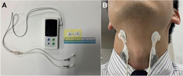
This composite clinical photograph illustrates a cervical percutaneous interferential current stimulation (IFC) device and its application for dysphagia or cough reflex therapy. Panel A shows the portable IFC unit, featuring a digital display and control buttons, connected via a bifurcated cable to four electrode connectors. A ruler is placed for scale alongside a pair of surface electrode pads. Panel B demonstrates the clinical application on a human subject. Two adhesive electrode pads are placed bilaterally on the anterior neck. The pads are positioned between the lower border of the mandibular angle and the anterior margin of the sternocleidomastoid muscle, targeting deep cervical structures. This setup is designed to deliver a 50 Hz interference current to facilitate swallowing-related muscle activation or sensory stimulation. The visual serves to guide clinicians on correct electrode placement and hardware configuration for neuromodulation in the context of neurogenic swallowing disorders, such as those seen in Parkinson's disease.
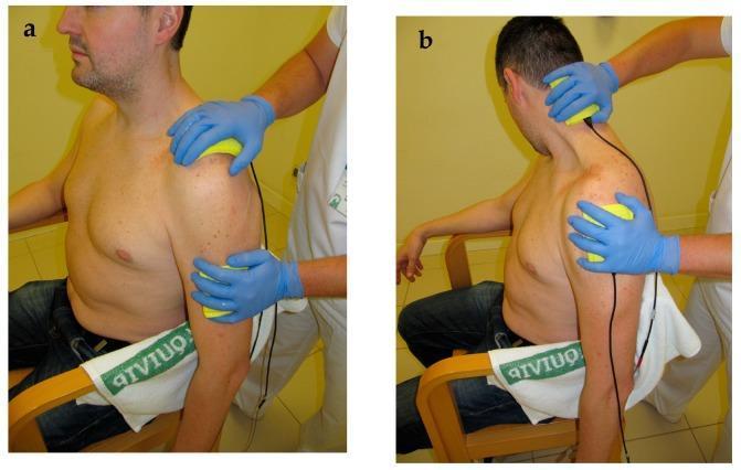
This clinical photograph illustrates the application of bipolar Interferential Therapy (IFT) electro-massage for musculoskeletal rehabilitation. The image is split into two panels: (a) showing the procedure with the patient in a neutral, upright seated position, and (b) demonstrating the procedure combined with active/passive stretching of the neck and shoulder musculature. A clinician wearing blue nitrile gloves is shown manually applying two yellow sponge-covered rubber electrodes to the patient's cervical-scapular and glenohumeral regions. The sponges are dampened to facilitate conductivity and smooth gliding over the skin during the massage. This technique is typically used in physical therapy to manage post-operative pain (such as after acromioplasty), improve range of motion, and target muscle groups like the upper trapezius and levator scapulae. The visual highlights the dynamic integration of electrotherapy with manual stretching to enhance therapeutic outcomes in the neck-shoulder complex.
IFT interferential therapy notes BK Nanda Clayton Low Reed physiotherapy definition types physiological effects
interferential therapy beat frequency waveform diagram medium frequency current
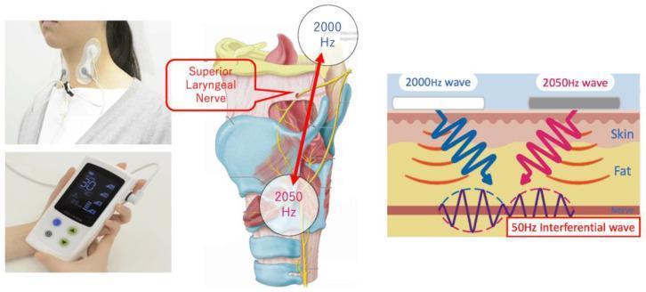
This composite educational image illustrates the application and mechanism of Transcutaneous Electrical Sensory Stimulation (TESS) for swallowing rehabilitation. The first panel shows a clinical photograph of surface electrodes positioned on the lateral cervical region of a patient. The central panel is an anatomical diagram of the larynx and pharynx, highlighting the superior laryngeal nerve. It demonstrates the placement of two frequencies—2000 Hz superiorly and 2050 Hz inferiorly—targeting the laryngeal structures. The final panel is a pathophysiology diagram explaining the interferential current (IFC) principle: two medium-frequency sine waves (2000 Hz and 2050 Hz) penetrate the skin and fat layers to intersect at the deeper nerve layer. This intersection creates a 50 Hz interferential wave, providing targeted stimulation to deep-seated nerves while minimizing superficial skin irritation. This technology is used for muscle atrophy amelioration and sensory stimulation in dysphagia management. The image also displays the 'Gentle-Stim' handheld control device.
This composite of three clinical photographs illustrates the electrode placement for two-channel interferential current (IFC) therapy aimed at bowel stimulation. (a) Anterior view: Two circular grey electrodes with orange and green color-coded connectors are placed bilaterally on the anterior abdominal wall below the costal margin. (b) Posterior view: Two corresponding electrodes are positioned on the patient's back flanking the spine between the T12 and L4 vertebrae. (c) Lateral view: Provides a profile of the cross-sectional alignment, demonstrating how the electrodes are situated to create a crossing current path through the abdominal cavity. The patient is shown in a supine position on a medical table. Pink insulated wires connect each electrode to the IFC device. This procedural configuration is used in physical therapy and gastroenterology to modulate intestinal motility using a carrier frequency (e.g., 5 kHz) and beat frequency without inducing painful muscle contractions.
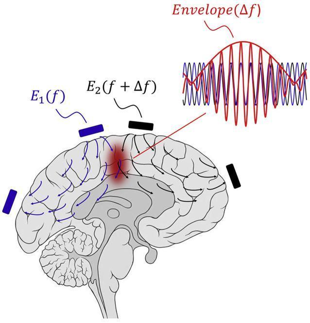
An anatomical diagram and pathophysiology illustration demonstrating the mechanism of Temporal Interference (TI) stimulation for noninvasive neuromodulation. The image features a sagittal-view stylized human brain with surface-mounted electrodes positioned to deliver oscillating electric fields. Two pairs of electrodes are shown: one set in blue, labeled E1(f), and one set in black, labeled E2(f + Δf). These generate intersecting electric field lines that penetrate deep into brain tissues. A localized red area highlights the target region where the two fields overlap. Above the brain, a waveform diagram illustrates the physics of the interference: two high-frequency sinusoidal waves (blue and red) overlap to produce a beat frequency, represented by a red 'Envelope(Δf)'. This envelope frequency (Δf) is significantly lower than the carrier frequencies, allowing for selective stimulation of deep neural structures while avoiding the activation of the superficial cortex. The diagram effectively teaches the concept of using high-frequency current offsets to achieve localized, focal deep brain stimulation without invasive electrodes.
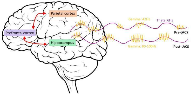
A combined neuroanatomical diagram and electrophysiological waveform illustration depicting the brain network involved in working memory and the effects of transcranial alternating current stimulation (tACS). The left side features a lateral view of the human brain with highlighted regions: the prefrontal cortex (purple), parietal cortex (orange), and hippocampus (green). Red arrows indicate bidirectional connectivity between the prefrontal cortex and hippocampus, and projections from the parietal cortex to the prefrontal cortex. The right side compares 'Pre-tACS' and 'Post-tACS' neural oscillations using wave patterns. Pre-tACS shows theta-gamma coupling with a 6Hz theta wave (purple) and 42Hz gamma bursts (yellow) at the peaks. Post-tACS demonstrates a frequency shift in the coupled gamma bursts to 80-100Hz, while maintaining the 6Hz theta rhythm. This infographic illustrates the mechanism of cross-frequency coupling manipulation to enhance cognitive function within the frontoparietal-hippocampal network.
https://copthnigadi.org/pdf/Econtent/Dr-chintan-solanki-IFT.…
INTERFERENTIAL THERAPY (IFT)
Complete Notes for BPT - Medium Frequency Currents
QUESTION a: Define IFT and its types (15 marks)
Definition
- Also known as Nemec's current after Dr. Hans Nemec who developed it in the early 1950s in Vienna, Austria.
- Medium frequency = 1,000 Hz to 10,000 Hz (typically 4,000 Hz carrier frequency is used).
- The two currents differ slightly in frequency (e.g., 4,000 Hz and 4,100 Hz), producing a beat frequency of 100 Hz at the point of interference.
Principle of Interference
Why Medium Frequency?
| Feature | Low Frequency | Medium Frequency |
|---|---|---|
| Skin impedance | HIGH (uncomfortable) | LOW (comfortable) |
| Tissue penetration | Superficial | Deep |
| Patient comfort | Painful | Comfortable |
| Selectivity | Non-selective | More selective |
Types of IFT
1. True/Classic IFT (4-pole / Quadripolar)
- Two independent medium-frequency circuits are applied using 4 electrodes (2 per circuit).
- The two currents physically cross inside the body tissues.
- Interference occurs within the tissues at the target site.
- Produces a clover-leaf shaped interference field.
- This is the original and most common form.
2. Pre-modulated IFT (2-pole / Bipolar)
- The interference is created within the IFT machine before delivery.
- Only 2 electrodes are required.
- The resultant amplitude-modulated current is then delivered to the tissues.
- Also called "pseudo-interferential" or "pre-modulated."
- No true tissue interference occurs.
- Simpler to apply; useful when only small areas are accessible.
3. Vector/Scanning IFT
- A variant of the 4-pole method.
- The interference field is automatically rotated through 360° by the machine.
- This ensures a larger tissue area is treated as the resultant current scans the region.
- Useful when the exact lesion site is uncertain.
- Achieves more uniform stimulation of a wider area.
QUESTION b: Explain the physiological effects of IFT (15 marks)
Beat Frequency and Corresponding Nerve Stimulation
| AMF/Beat Frequency | Effect |
|---|---|
| 1-5 Hz | Strong muscle contraction (fast twitch); denervated muscle stimulation |
| 5-10 Hz | Stimulates parasympathetic nerves; promotes circulation |
| 10-50 Hz | Stimulates motor nerves; produces rhythmic muscle contractions |
| 50-90 Hz | Sedative and spasmolytic effect; reduces muscle spasm |
| 90-100 Hz | Analgesic (pain relief) - activates pain gate control mechanism |
| 100-150 Hz | Stimulates sensory nerves; pain relief via opioid release |
1. Pain Relief
- High-frequency IFT (80-100 Hz) activates large-diameter Aβ nerve fibres.
- These fibres stimulate inhibitory interneurons in the dorsal horn (substantia gelatinosa).
- This "closes the gate" to painful stimuli traveling on small C-fibres and Aδ-fibres.
- Provides immediate but short-duration pain relief.
- Low-frequency IFT (2-4 Hz) stimulates the pituitary and hypothalamus to release endorphins and enkephalins.
- These endogenous opioids bind to opioid receptors in the brain and spinal cord.
- Provides longer-lasting pain relief (post-stimulation analgesia).
2. Motor Stimulation / Muscle Contraction
- Frequencies of 10-50 Hz produce rhythmic contractions of skeletal muscle.
- Used to strengthen weak or atrophied muscles.
- Helps maintain muscle bulk during periods of immobilization.
- Can reduce muscle spasm at 50-90 Hz.
3. Improved Blood Circulation
- Rhythmic muscle contraction produced by IFT acts as a muscle pump.
- Dilates blood vessels (vasodilation) at the treatment site.
- Improves local arterial and venous circulation.
- Aids in the removal of metabolic waste products (lactic acid, bradykinin).
- Promotes tissue healing and reduces ischemic pain.
4. Reduction of Oedema
- IFT causes rhythmic muscle contractions that create a pumping effect.
- Stimulates lymphatic drainage and venous return.
- Promotes reabsorption of interstitial fluid.
- Particularly useful in sub-acute post-traumatic oedema.
- The use of suction electrodes can enhance this effect.
5. Tissue Healing and Repair
- Improved circulation brings oxygen and nutrients to injured tissues.
- Stimulates fibroblast activity, promoting collagen synthesis.
- Enhances tissue regeneration in chronic wounds and soft tissue injuries.
6. Reduction of Muscle Spasm
- AMF at 50-90 Hz produces a sedative effect on muscle.
- Causes fatigue of muscle in spasm, leading to relaxation.
- Also reduces pain that may be maintaining the spasm (pain-spasm cycle is broken).
QUESTION c: Explain the therapeutic effects of IFT (15 marks)
1. Analgesia (Pain Management)
- Immediate analgesia via gate control (high AMF: 80-100 Hz)
- Delayed analgesia via endorphin release (low AMF: 2-4 Hz)
- Effective for acute and chronic pain conditions: OA knee, LBP, cervical spondylosis, post-surgical pain.
2. Muscle Stimulation
- Denervated muscle stimulation at 0.5-5 Hz (prevents atrophy)
- Innervated muscle strengthening at 10-50 Hz
- Effective in post-immobilization weakness, quadriceps wasting, peripheral nerve lesions
3. Reduction of Oedema and Inflammation
- Lymphatic drainage effect through muscular pumping action
- Reduces post-acute oedema in ankle sprains, post-fracture swelling
- Anti-inflammatory via improved circulation and metabolite clearance
4. Tissue Repair / Wound Healing
- Enhanced vascularity promotes cellular metabolism
- Promotes fibroplasia and collagen formation in soft tissue repair
5. Treatment of Stress Incontinence
- Low AMF (5-10 Hz) used to strengthen pelvic floor muscles (levator ani, external urethral sphincter)
- Used in female stress urinary incontinence
6. Spasmolysis
- AMF 50-90 Hz selectively fatigues hypertonic muscles
- Breaks the vicious cycle of pain causing spasm causing more pain
7. Facilitation of Joint Mobility
- Pain reduction and muscle relaxation together improve range of motion
- Used as adjunct before exercise therapy or manual therapy
QUESTION d: Enumerate the appropriate dose to bring about the desired physiological and therapeutic effect (15 marks)
Dose Parameters in IFT
1. Carrier Frequency
- Standard: 4,000 Hz (most common)
- Some machines use 2,500 Hz or up to 10,000 Hz
2. Amplitude Modulated Frequency (AMF / Beat Frequency)
| Clinical Goal | AMF (Hz) | Duration |
|---|---|---|
| Acute pain relief | 80-100 Hz | 15-20 min |
| Chronic pain | 2-4 Hz or 80-100 Hz | 20-30 min |
| Muscle strengthening | 25-50 Hz | 15-20 min |
| Oedema reduction | 5-20 Hz | 20 min |
| Muscle spasm | 50-100 Hz | 15-20 min |
| Stress incontinence | 5-20 Hz | 15-20 min |
| Denervated muscle | 0.5-1 Hz | 20 min |
3. Sweep/Frequency Modulation
- A sweep or swing control automatically varies the AMF within a set range.
- Prevents nerve/muscle accommodation (adaptation to a constant frequency).
- Types of sweep patterns: Trapezoidal, Triangular, Rectangular.
- Example: A sweep of 90-100 Hz for pain relief; sweep of 10-50 Hz for muscle work.
4. Current Intensity
- Should be set to produce the desired sensation:
- Sensory threshold (tingling only): for pain relief (80-100 Hz)
- Motor threshold (visible contraction): for muscle stimulation
- Strong motor contraction: for muscle strengthening/oedema
- Increase intensity gradually until patient reports the desired sensation.
- Never cause pain with intensity.
5. Treatment Duration
- Acute conditions: 10-15 minutes
- Chronic conditions: 20-30 minutes
- Daily or alternate-day sessions.
- Typical course: 6-12 sessions.
6. Electrode Size
- Larger electrodes: larger treatment area, more comfortable
- Smaller electrodes: focused stimulation on small structures
7. Number of Sessions
- Acute: 3-6 sessions
- Chronic: 10-15 sessions
- Reassess after 3rd session for progress.
QUESTION e: Explain techniques - different methods of application of IFT (15 marks)
Pre-Treatment Checklist
- Check the machine is in working order (test on self).
- Explain the procedure and obtain informed consent.
- Inspect the skin for abrasions, cuts, or infections - avoid treating over these.
- Position the patient comfortably with the area to be treated exposed.
- Check for contraindications.
- Educate the patient on what sensation to expect (tingling, buzzing, muscle twitching).
Method 1: Quadripolar (4-Electrode) Technique
- 4 electrodes (suction cups or flat pads) placed around the target site.
- Electrodes from Circuit 1 (red) placed diagonally opposite each other.
- Electrodes from Circuit 2 (black) placed in the remaining diagonal positions.
- The two circuits cross at right angles (90°), and the interference field forms at their crossing point over the lesion.
- The electrodes of each circuit are placed so the currents cross at the lesion.
- The currents must cross as close to 90° as possible for maximum interference.
- The electrodes must be of equal size within each circuit.
- The skin-electrode contact must be uniform (use wet sponge pads or suction cups).
Method 2: Bipolar (2-Electrode / Pre-modulated) Technique
- Only 2 electrodes used.
- Interference happens inside the machine.
- Simpler and faster to set up.
- Used on small areas: fingers, toes, small joints.
- Suitable when patient cannot tolerate suction.
Method 3: Coplanar Technique
- All 4 electrodes are placed on the same surface (same plane) of the body.
- Used when the target is close to the surface.
- For example, treating the spine: all electrodes placed on the back.
Method 4: Suction Electrode Technique
- Suction cups hold electrodes in contact without manual pressure.
- Most hygienic and comfortable.
- The suction itself provides mild massage effect, assisting lymphatic drainage.
- Used over larger joints: knee, hip, shoulder.
- Patients can perform gentle exercises during treatment.
Method 5: Vector/Scanning Mode
- Available on advanced IFT machines.
- The interference field rotates through 360° automatically.
- Useful when the exact treatment area is large or diffuse.
- Treats a wider field with one application.
Electrode Media
| Type | Use |
|---|---|
| Suction cups (with water) | Joints, larger areas |
| Flat rubber electrodes with wet sponge | General use |
| Adhesive pad electrodes | Pre-modulated/bipolar use |
Steps of Application (Quadripolar)
- Prepare electrodes: fill suction cups with water, or dampen sponge pads.
- Position electrodes diagonally around the lesion.
- Set carrier frequency (4,000 Hz).
- Set AMF/beat frequency according to treatment goal.
- Set sweep range.
- Gradually increase intensity to required level.
- Treat for 15-30 minutes.
- Slowly reduce intensity to zero at end of treatment.
- Remove electrodes; inspect skin.
- Document treatment parameters.
QUESTION f: Describe different types of Electrodes (including vacuum), its Effects and Uses (15 marks)
Types of Electrodes
1. Suction/Vacuum Electrodes
- Transparent plastic or rubber cup.
- Contains a carbon rubber electrode or conductive material inside.
- Connected to a suction pump on the IFT machine.
- Water or electrolytic gel is placed inside the cup before use.
- The suction pump creates a partial vacuum, drawing the skin into the cup.
- This holds the electrode firmly in contact without strapping or manual pressure.
- Provide excellent, constant electrical contact.
- The suction creates mild mechanical massage effect - helps mobilize tissue fluid.
- Acts as a pneumatic massage, enhancing lymphatic drainage.
- Increases local blood flow (hyperemia) from the suction effect.
- Combine electrical stimulation with mechanical suction for enhanced oedema reduction.
- Over large joints: knee, hip, shoulder, ankle.
- When treating oedema - suction enhances lymphatic drainage.
- When long treatment times are required (patient comfort).
- When hands-free operation is needed.
- During exercise-combined IFT.
- Hands-free - therapist can assist patient with exercises.
- Hygienic (each cup used for one patient).
- Consistent contact pressure.
- Additional massage effect via suction.
- Cannot be used over bony prominences.
- Cannot be used where skin is fragile.
- Cannot be used in areas with poor circulation.
2. Flat Rubber (Carbon Rubber) Electrodes with Sponge Pads
- Flexible carbon-rubber electrodes.
- Covered with water-dampened sponge pads for electrical contact.
- Held in place with rubber straps or bandages.
- Available in various sizes.
- Used with sponge interface to reduce skin irritation.
- Best for flat body areas.
3. Self-Adhesive Electrodes (Pad Electrodes)
- Hydrogel-coated adhesive pads.
- Used primarily with pre-modulated/bipolar IFT.
- Single-use or limited-reuse.
- Convenient for small areas.
- Do not require straps.
4. Roller Electrodes
- Cylindrical electrode that can be rolled over the skin surface.
- Used in bipolar IFT/electromassage techniques.
- The therapist moves the electrode over the treatment area.
- Provides combined electrical stimulation and massage.
Electrode Size Selection
| Treatment Area | Electrode Size |
|---|---|
| Large muscles/joints | Large (10x10 cm or suction cups) |
| Medium joints | Medium (7x7 cm) |
| Small joints/localized area | Small (3x3 cm) |
| Digits | Bipolar with small pads |
Uses of IFT Electrodes
- Accurate placement of electrodes determines the zone of interference.
- Proper electrode selection ensures patient comfort and treatment efficacy.
QUESTION g: Explain indications, contraindications, dangers and precautions of IFT (15 marks)
INDICATIONS OF IFT
Musculoskeletal Conditions:
- Osteoarthritis (knee, hip, cervical, lumbar)
- Rheumatoid arthritis (sub-acute phase)
- Shoulder conditions: adhesive capsulitis, rotator cuff tendinopathy
- Lumbar spondylosis / low back pain (LBP)
- Cervical spondylosis / neck pain
- Plantar fasciitis
- Ankle sprain (sub-acute and chronic)
- Post-fracture rehabilitation (oedema, pain, muscle wasting)
- Muscle strain and ligament sprains (sub-acute)
Neurological / Neuromuscular:
- Peripheral nerve lesions (for denervated muscle stimulation)
- Post-nerve injury rehabilitation
- Painful neurological conditions (neuralgia, radiculopathy)
- Muscle atrophy from disuse
Cardiorespiratory / Circulatory:
- Poor peripheral circulation (chronic)
- Raynaud's disease (with caution)
- Venous oedema in limbs
Other:
- Stress urinary incontinence (pelvic floor strengthening)
- Post-operative pain and oedema
- Sports injuries
- Dysmenorrhea (menstrual pain)
CONTRAINDICATIONS OF IFT
Absolute Contraindications (IFT should NOT be used):
| Contraindication | Reason |
|---|---|
| Cardiac pacemaker | Electrical current may interfere with pacemaker function |
| Malignancy / Cancer over treatment site | May stimulate tumour growth or spread |
| Deep Vein Thrombosis (DVT) | Risk of dislodging thrombus |
| Active Haemorrhage / Fresh bleeding | Increased circulation worsens bleeding |
| Skin infections / Open wounds | Risk of spreading infection; burns |
| Pregnancy (over abdomen/lower back) | Risk to foetus; may stimulate uterine contractions |
| Epilepsy (over head/neck) | May precipitate seizure |
| Impaired sensation over treatment area | Cannot report discomfort; risk of burns |
| Acute inflammatory conditions | Can worsen inflammation |
Relative Contraindications (use with caution):
- Over carotid sinus (may cause reflex bradycardia)
- Over the eyes or head
- Patients with metal implants at treatment site (risk of heat)
- Patients on anticoagulants
- Hypertension
DANGERS OF IFT
- Burns - from excessive intensity, dry sponge pads, or prolonged treatment
- Increased pain - may occur if wrong frequency or intensity used; or in acute conditions
- General malaise - feeling of weakness/tiredness post-treatment
- Nausea - particularly when treating the trunk
- Dizziness - especially when treating the head, neck, or vestibular region
- Migraine - in susceptible patients, head/neck treatment may trigger
- Skin irritation - under electrodes; from pressure or chemical reaction with gel
- Allergic reaction - to electrode gel or sponge material
- Fainting (vasovagal response) - rarely, from intense stimulation
- Interference with implanted devices - pacemakers, cochlear implants
PRECAUTIONS
- Always test the machine before use on a functioning model or self.
- Inspect the patient's skin thoroughly before each session.
- Warn the patient to report any burning, discomfort, or increased pain immediately.
- Never increase intensity rapidly - always increase gradually.
- Do not treat over wet skin (other than properly prepared electrode-sponge system).
- Ensure electrodes are firmly and evenly in contact - loose electrodes cause burns.
- Reduce intensity to zero before removing electrodes.
- Treat duration should not exceed 30 minutes in most cases.
- Document all parameters used.
- Reassess after each session - if no improvement in 3-4 sessions, review the treatment plan.
IFT MACHINE PANEL - KEY COMPONENTS DIAGRAM
┌──────────────────────────────────────────────────────┐
│ IFT MACHINE PANEL │
├────────────┬───────────────┬────────────┬────────────┤
│ CARRIER │ AMF / BEAT │ SWEEP │ INTENSITY │
│ FREQUENCY │ FREQUENCY │ CONTROL │ CONTROL │
│ (4000 Hz) │ (1-250 Hz) │ (Swing %) │ (mA) │
├────────────┴───────────────┴────────────┴────────────┤
│ TIMER │
│ (0-30 minutes) │
├─────────────────────────────────────────────────────┤
│ CIRCUIT 1 OUTPUT │ CIRCUIT 2 OUTPUT │
│ (Red terminals) │ (Black terminals) │
│ Electrode 1A & 1B │ Electrode 2A & 2B │
└─────────────────────────────────────────────────────┘
SUMMARY TABLE: IFT AT A GLANCE
| Parameter | Details |
|---|---|
| Full Name | Interferential Therapy |
| Developer | Dr. Hans Nemec (1950s, Vienna) |
| Also Called | Nemec's Current |
| Carrier Frequency | 4,000 Hz (medium frequency) |
| Beat Frequency (AMF) | 1-250 Hz (therapeutic range) |
| Types | Quadripolar, Bipolar/Pre-modulated, Vector |
| Electrode Types | Suction, Carbon rubber, Adhesive pads |
| Key Physiological Effects | Analgesia, Motor stimulation, Oedema reduction, Spasm relief |
| Treatment Duration | 15-30 minutes per session |
| Frequency of Sessions | Daily or alternate day; 6-15 sessions |
| Primary References | Clayton, Low & Reed, BK Nanda |
REFERENCES
- Clayton, E. - Clayton's Electrotherapy (3rd & 10th editions) - Primary reference for all IFT parameters, types, and application techniques.
- Low, J. & Reed, A. - Electrotherapy Explained: Principles and Practice - Comprehensive physiological basis of IFT; frequency effects; clinical applications.
- Nanda, B.K. - Textbook of Electrotherapy - Indian standard reference for BPT; practical protocols and clinical use of IFT.
Exam Tip: Each of the 7 syllabus objectives (a-g) maps to a 15-mark question. Structure your answer with: Definition/Concept (3 marks) + Detailed Explanation with Classification (7 marks) + Diagram (3 marks) + Clinical Application (2 marks). Always mention frequency ranges for physiological effects and always cite Clayton/Low & Reed/BK Nanda in your answer.