
Surgical anatomy of temporal bone
temporal bone surgical anatomy diagram
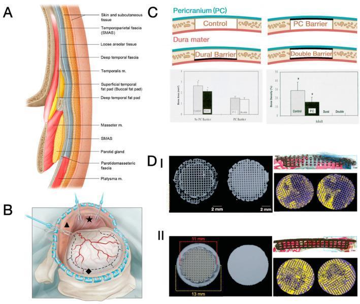
Educational panel illustrating cranial surgical anatomy and bone regeneration research. Panel A: A cross-sectional anatomical diagram of the calvarial and temporal regions labeling multiple soft tissue layers, including the skin, subcutaneous tissue, temporoparietal fascia (SMAS), loose areolar tissue, deep temporal fascia, temporalis muscle, and fat pads. Panel B: A surgical illustration of a craniectomy, showing reflected scalp and dissected temporalis muscle over the dura mater. Panel C: Scientific schematic and bar charts evaluating the inhibitory effects of mechanical barriers (pericranium and dural barriers) on bone regeneration in rat cranial defects. Panel D: Pre-implantation photographs and post-surgical histology of β-TCP scaffolds used in rabbit models. Sub-panels I (porous cap) and II (solid cap) display circular lattice scaffolds, Stevenel’s blue/Van Gieson staining (SVG) for tissue differentiation (mineralized bone in red, soft tissue in blue), and micro-CT reconstructions highlighting new bone formation in yellow at 8 weeks post-operation. This visual resource is designed for advanced learners in neurosurgery and tissue engineering.
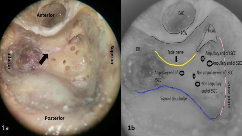
This medical visual consists of two parts: a clinical photograph of a surgical dissection (1a) and a corresponding anatomical diagram (1b) focusing on the surgical anatomy of the left temporal bone. Image 1a shows a cortical mastoidectomy and labyrinthectomy, highlighting the facial nerve (indicated by a black arrow) situated in the posterior canal wall. The orientation labels show the anterior, posterior, superior, and inferior margins of the operative field. Image 1b is an illustrative overlay depicting key landmarks for otologic surgery, including the facial nerve (yellow line), the sigmoid sinus bulge (blue line), and the dural or tegmen plate (pink dotted line). The diagram further identifies the external auditory canal (EAC), posterior canal wall (PCW), and the digastric ridge (DR). Specific surgical landmarks for the vestibular system are noted, including the ampullary and non-ampullary ends of the lateral (LSCC), posterior (PSCC), and superior (SSCC) semicircular canals, as well as the position of the incus. This content is intended for intermediate to advanced otorhinolaryngology education regarding mastoid surgery and facial nerve identification.
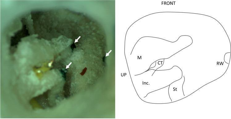
This composite image consists of an otoendoscopic clinical photograph (left) and a corresponding anatomical line diagram (right) of a right human temporal bone in an operative position. The photograph illustrates a qualitative analysis of microneedle injection accuracy within the middle ear cleft. Three target areas are identified by black ink droplets (marked with white arrowheads) and one red ink droplet, serving as markers for localization. The anatomical diagram provides orientation, labeling key structures of the middle ear: the malleus (M), incus (Inc.), stapes (St), chorda tympani (CT), and the round window (RW) niche. The view is oriented with 'FRONT' and 'UP' markers, simulating a surgical approach through the external auditory canal. The visible bone surface displays a textured, porous morphology characteristic of the mastoid/tympanic region. This visual material is designed for educational use in otolaryngology, specifically regarding surgical navigation, augmented reality systems in ear surgery, and middle ear anatomy.
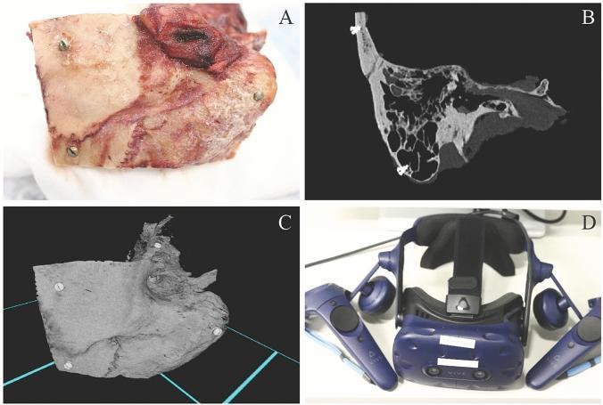
This composite educational image illustrates the multimodal representation of human temporal bone (TB) anatomy for surgical training. Panel A shows a clinical photograph of a fresh frozen temporal bone specimen, displaying natural coloration with red hues from residual soft tissue and blood vessels. Five titanium fiducial marker screws are visible, placed at predefined locations (squamous part, mastoid tip, and petrous part) for measurement validation. Panel B presents a 2D high-resolution computed tomography (HRCT) image in a grayscale bone window, clearly detailing internal structures like mastoid air cells and the bony labyrinth. Panel C displays a 3D virtual reality (VR) reconstruction of the specimen, emphasizing surface morphology and the spatial orientation of the fiducial markers within a digital environment. Panel D shows the hardware used for interaction, specifically an HTC Vive Pro head-mounted display and controllers. The set demonstrates the translation of physical specimens into diagnostic imaging and immersive VR simulations for otologic surgical planning and anatomical study.
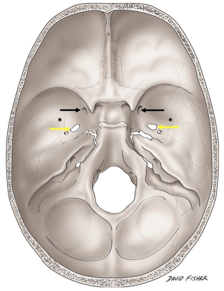
Anatomical Diagram: Superior view (internal aspect) of the human skull base. This medical illustration highlights the bony landmarks and foramina of the anterior, middle, and posterior cranial fossae. Black arrows indicate the bilateral foramina rotundum, while yellow arrows point to the bilateral foramina ovale. Asterisks (*) denote unusual bilateral variant foramina situated approximately 3.1 cm lateral to the standard midline foramina, near the sphenotemporal suture. The diagram clearly depicts the sphenoid bone, temporal bone, and occipital bone transitions, illustrating the spatial relationship between neurovascular exit points and the infratemporal fossa roof. This schematic is designed for osteological study and surgical anatomy education, focusing on anatomical variations within the middle cranial fossa that may be relevant during skull base procedures or diagnostic imaging interpretation.
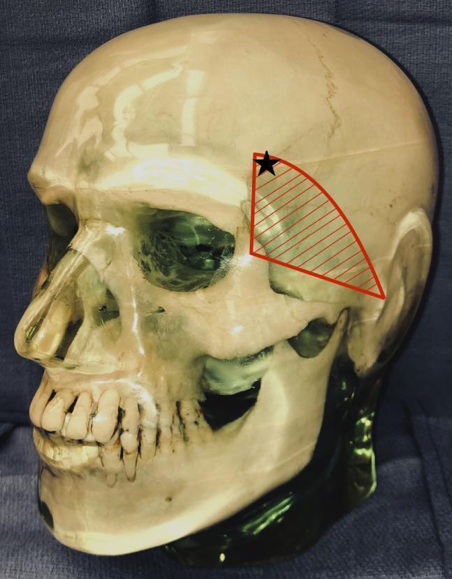
This anatomical diagram utilizes a lateral view of a human skull model to illustrate the surgical vulnerability of the temporal branch of the facial nerve. A red hatched triangular region is overlaid on the temporal fossa, bounded by the zygomatic arch inferiorly, the zygomatic process of the frontal bone anteriorly, and extending toward the superior temporal line. This area represents the danger zone where the temporal branch of the facial nerve is most superficial. A black star is marked within the superior-anterior portion of this shaded region, indicating the specific placement of a Mayfield head clamp pin that resulted in postoperative frontalis muscle palsy. The image serves as a clinical education tool for neurosurgical and orthopedic surgical positioning, highlighting the risk of iatrogenic nerve injury from external fixation devices when applied near the course of the facial nerve branches.
mastoid air cells facial nerve canal temporal bone cross section
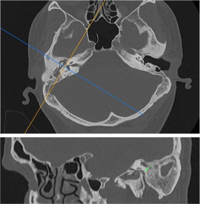
This medical visual consists of two panels showcasing Multidetector Computed Tomography (MDCT) of the temporal bone for anatomical assessment of the facial nerve (CN VII). The top panel displays an axial thin-section MDCT scan at the level of the skull base, featuring blue and orange planning lines used to generate multiplanar reformats. The bottom panel displays a reformatted sagittal view derived from the axial data. This sagittal section clearly illustrates the intraosseous course of the facial nerve canal within the temporal bone. Key anatomical landmarks demonstrated include the tympanic segment, the sharp angulation at the second genu, and the descending mastoid (vertical) segment. Surrounding structures such as the mastoid air cells, tympanic cavity, and the relationship of the facial canal to the posterior wall of the external auditory canal are visible. The green arrow specifically highlights the region of the second genu. This type of multiplanar reformatting is clinically essential for preoperative planning in otologic surgery and for evaluating facial canal dehiscence or traumatic injury.
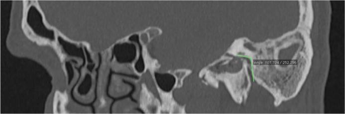
This diagnostic image is a sagittal reformatted Multidetector Computed Tomography (MDCT) scan of the human temporal bone and midface region. The anatomical focus is the course of the facial nerve canal within the temporal bone. Key visible structures include the mastoid air cells with their characteristic trabecular pattern, the middle ear cavity, and the paranasal sinuses anteriorly. The image features a quantitative assessment where two green linear annotations are superimposed to track the facial nerve's trajectory. One line follows the horizontal tympanic segment, while the second line follows the vertical mastoid segment. These lines intersect at the second genu of the facial canal, and a digital measurement box displays the resulting angle (107.7 degrees). This radiographic technique is used in otolaryngology and radiology for preoperative surgical planning and anatomical variation assessment, particularly to identify the precise angulation of the facial nerve to avoid iatrogenic injury during mastoidectomy or middle ear surgery.
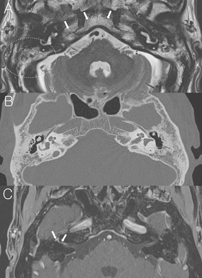
This composite figure consists of three axial imaging views of the temporal bone and skull base in a patient with Bell's palsy, demonstrating sclerotic mastoid changes. (A) Non-contrast axial T2-weighted MRI at the level of the internal auditory canal (IAC) shows heterogeneous high signal intensity within the mastoid air cell region (indicated by a dotted circle), matching the signal of the adjacent clivus and petrous apex marrow (arrows). (B) Axial temporal bone CT scan (TBCT) provides anatomical correlation, showing significant bony sclerotic changes and a marked reduction in the number of mastoid air cells compared to normal pneumatization. (C) Post-contrast axial T1-weighted MRI at the level of Bill's bar demonstrates pathologic enhancement of the right facial nerve involving the distal canalicular, labyrinthine, and geniculate ganglion segments (arrows). The images collectively illustrate how chronic mastoid sclerosis, an anatomical variant, can appear on MRI and CT, while also showing the characteristic nerve enhancement associated with acute peripheral facial nerve palsy.
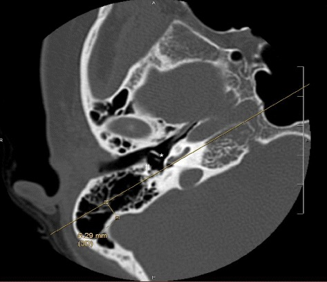
**Imaging Modality:** High-resolution computed tomography (HRCT) of the temporal bone. **Anatomical Region:** Axial section of the right petrous temporal bone and middle ear. **Key Landmarks and Features:** The image displays the internal auditory canal, the cochlea, and the pneumatized mastoid air cells. Specific annotation marks identify the round window niche (*) and the descending (mastoid) segment of the facial nerve (#). A linear trajectory is projected passing through these two anatomical landmarks, extending posteriorly toward the mastoid cortex. **Measurements and Observations:** A quantitative measurement of 6.29 mm is visible, representing the distance between the reference line (aligned with the round window and facial nerve) and the anterior border of the sigmoid sinus. The sigmoid sinus is visualized as a well-defined cortical groove posterior to the mastoid antrum. **Clinical Context:** This preoperative measurement assesses the surgical corridor for a posterior tympanotomy or cochlear implantation. It evaluates the degree of sigmoid sinus anteriorization, which can influence surgical access to the middle ear via the facial recess. The image demonstrates a standard anatomical relationship without evidence of ossicular pathology or significant mastoid opacification.
middle ear ossicles malleus incus stapes anatomy
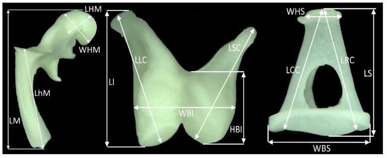
Anatomical comparison and morphometric analysis of the three auditory ossicles from the middle ear: the malleus, incus, and stapes. The image displays the bones individually against a dark background, highlighted with white arrows and abbreviations indicating specific linear and width measurements. 1. Malleus (Left): Demonstrates measurements for total length (LM), length and width of the head (LHM, WHM), and length of the handle or manubrium (LhM). 2. Incus (Middle): Resembles a molar tooth with measurements for total length (LI), length of the long crus (LLC), length of the short crus (LSC), and the height and width of the body (HBI, WBI). 3. Stapes (Right): A stirrup-shaped bone showing total length (LS), length of the caudal and rostral crura (LCC, LRC), width of the head (WHS), and width of the base/footplate (WBS). This diagram serves as a morphometric guide for identifying structural landmarks and quantifying the size proportions of the ossicular chain used in comparative anatomy and audiological research.
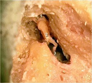
This clinical photograph provides a cadaveric dissection view of the middle ear cavity, illustrating the anatomical arrangement of the human ossicular chain. The image displays the three primary ossicles in their healthy, articulated positions. The head of the malleus (labeled 1) is shown in close physical contact with the body of the incus (labeled 2), forming a normal incudo-malleolar joint. Progressing medially and inferiorly, the long process of the incus (2) is seen in direct continuity with the head of the stapes (labeled 3) at the incudo-stapedial joint. The surrounding temporal bone has been partially dissected to expose the tympanic cavity, highlighting the relative spatial orientation of these structures. This image serves as a reference for normal anatomy in the assessment of post-traumatic ossicular luxation or middle ear pathology. It is intended for intermediate to advanced medical learners studying otolaryngology or temporal bone radiology.
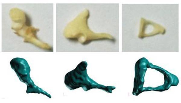
A comparison chart showcasing the three human auditory ossicles of the middle ear: the malleus (left), incus (center), and stapes (right). The image is organized into two rows to contrast real anatomical specimens with digital reconstructions. The top row features clinical photographs of actual ossicles harvested from a temporal bone, displaying natural biological variations in off-white to tan bone color, subtle surface textures, and fine morphology. The bottom row presents corresponding 3D solid models, likely generated via micro-CT scanning for finite element (FE) modeling. These digital renderings are depicted in a uniform teal color with smoothed surfaces and idealized geometries. The malleus is shown with its distinct bulbous head and elongated manubrium; the incus displays its characteristic body and short and long processes; and the stapes is identified by its small, stirrup-like triangular shape and central opening. This visual aid is designed for advanced medical education in otorhinolaryngology and biomechanical engineering, illustrating the translation of complex anatomical structures into simplified computational models for middle ear research.
Surgical Anatomy of the Temporal Bone
Overview
- Cummings Otolaryngology, Ch. 126 (Francis HW)
- Shambaugh Surgery of the Ear, Anatomy of the Temporal Bone
1. Parts of the Temporal Bone
| Part | Key Features |
|---|---|
| Squamous | Forms the lateral (temporal) surface; contains the zygomatic process and root of zygoma; contributes to middle cranial fossa floor |
| Petrous | Dense, pyramidal bone housing the inner ear, IAC, carotid canal, and apex; runs obliquely medially |
| Tympanic | Forms most of the bony EAC (external auditory canal) and the tympanic ring |
| Mastoid | Posterior projection; contains mastoid air cells, antrum, and canal for facial nerve |
| Styloid | Projects inferiorly below the tympanic bone; origin of stylohyoid ligament and muscles |
2. Lateral Surface - Key Surgical Landmarks
- Temporal line (linea temporalis): A ridge running posteriorly and slightly superiorly from the root of the zygoma. It marks the inferior border of the temporalis muscle and approximates the floor of the middle cranial fossa. The temporal line is located approximately 5 mm inferior to the lowest level of the middle fossa floor.
- Spine of Henle (suprameatal spine): A prominence of variable size at the posterosuperior rim of the EAC. The mastoid antrum lies approximately 1.5 cm deep to this point at the same level.
- Macewen's triangle (fossa mastoidea / cribriform area): Bounded by the temporal line superiorly, a tangent to the posterior EAC posteriorly, and the posterosuperior rim of the canal. It is characterized by multiple small perforating vessels. This triangle overlies the mastoid antrum and is the entry point for cortical mastoidectomy.
- Mastoid tip: Easily palpated; landmark for postauricular incision placement. The digastric groove (mastoid incisure) lies posterior and medial to the tip, indicating the insertion of the posterior belly of digastric.
- Stylomastoid foramen: Located at the anterior limit of the digastric groove and is the exit point of the facial nerve from the temporal bone. The tympanomastoid fissure can be traced medially to reach it - caution is required when dissecting anterior to the mastoid tip, especially in young children in whom the tip is undeveloped.
- Tympanosquamous suture: Anterosuperior part of the tympanic ring.
- Glenoid fossa: Lies anterior to the tympanic ring beneath the root of the zygoma; the temporomandibular joint occupies this region.
3. Superior Surface (Tegmen) - Middle Cranial Fossa Floor
- Tegmen tympani: Anterior part, forms roof of the tympanic cavity, separating it from the temporal lobe.
- Tegmen mastoideum: Posterior part, overlies mastoid air cells.
- Arcuate eminence: Present in ~85% of temporal bones. Approximates the position of the superior semicircular canal (SSCC) and is a key landmark in middle cranial fossa surgery.
- Greater petrosal nerve (GPN): Separates from the geniculate ganglion, emerges through the facial hiatus, and runs in a groove medial to the petrotympanic suture toward the foramen lacerum. It carries parasympathetic fibers to the pterygopalatine ganglion and is a landmark for the geniculate ganglion in middle fossa approaches.
- Lesser petrosal nerve: Lateral and parallel to the GPN; carries parasympathetic fibers to the parotid gland via the otic ganglion.
- Gasserian ganglion: Lies in a depression at the lateral petrous apex.
- Foramen ovale (mandibular nerve V3) and foramen spinosum (middle meningeal vessels): Serve as anterior surgical landmarks.
4. Posterior Surface - Posterior Cranial Fossa
- Sigmoid sulcus: An indentation at the lateral aspect accommodating the sigmoid sinus.
- Endolymphatic sac fossa: Anterior to the sigmoid sulcus; houses the intradural portion of the endolymphatic sac. The operculum (a bony ledge) covers the intraosseous portion.
- Vestibular aqueduct: Runs from the operculum anteriorly, superiorly, and medially to the medial wall of the vestibule.
- Superior petrosal sulcus: At the junction of the posterior and middle cranial fossa plates; carries the superior petrosal sinus from the sigmoid sinus to the cavernous sinus.
5. Internal Auditory Canal (IAC)
- Upper compartment: Facial nerve (anterior) and superior vestibular nerve (posterior), separated by Bill's bar (vertical crest)
- Lower compartment: Cochlear nerve (anterior) and inferior vestibular nerve (posterior)
6. External Auditory Canal (EAC)
- Outer one-third: cartilaginous, contains ceruminous glands and hairs; anteroinferior wall has fissures of Santorini (sites of tumor spread to parotid)
- Inner two-thirds: bony, formed by the tympanic bone
- Foramen of Huschke: Defect in the floor of the bony EAC (present in ~25%), allowing tumor spread from EAC to infratemporal fossa and parotid
7. Middle Ear (Tympanic Cavity)
| Compartment | Location | Contents |
|---|---|---|
| Epitympanum (Attic) | Above the level of TM | Head of malleus, body and short process of incus, Prussak's space |
| Mesotympanum | At the level of TM | Ossicular chain (long process of incus, stapes), oval window, round window, promontory |
| Hypotympanum | Below the TM | Floor of middle ear; jugular bulb below |
| Protympanum | Anterior (tube end) | Eustachian tube opening, carotid artery medially |
| Posterior tympanum | Behind oval window | Sinus tympani, facial recess, pyramidal eminence |
Medial Wall Landmarks (Surgical)
- Cochlear promontory: Formed by the basal turn of the cochlea; bears the tympanic plexus (Jacobson's nerve, CN IX branch)
- Oval window (fenestra vestibuli): Occupied by the stapes footplate; the facial nerve runs directly above it - most common site of facial nerve dehiscence
- Round window (fenestra cochleae): Inferoposterior to oval window; sealed by the secondary tympanic membrane; target for drug delivery and cochlear implantation
- Stapes: Consists of head, neck, anterior and posterior crura, and footplate. The stapedial tendon (from pyramidal eminence) attaches to the neck
- Sinus tympani: Recess posterior to the oval window, medial to the vertical facial nerve - a site for occult cholesteatoma that is difficult to visualize
Ossicular Chain
- Malleus: Manubrium embedded in the TM; head articulates with incus in the epitympanum
- Incus: Most vulnerable ossicle - the long process has a single nutrient vessel and lacks collateral circulation, making it susceptible to avascular necrosis
- Stapes: Smallest bone in the body; footplate seals the oval window
8. Facial Nerve - Intratemporal Course

Segments and Key Points
| Segment | Course | Length | Surgical Significance |
|---|---|---|---|
| Meatal (IAC) | From brainstem to meatal foramen | ~8-10 mm | Lies anterosuperior to vestibulocochlear nerve |
| Labyrinthine | Meatal foramen to geniculate ganglion | ~3-5 mm | Narrowest segment (0.61-0.68 mm); watershed circulation; most vulnerable to ischemic/herpetic injury |
| Tympanic (horizontal) | Geniculate ganglion to pyramidal eminence (2nd genu) | ~11 mm | Runs above oval window; most frequently dehiscent (up to 55%) |
| Mastoid (vertical) | 2nd genu to stylomastoid foramen | ~13 mm | Courses medial to the tympanic annulus plane |
Key Landmarks for Identification
- Cochleariform process (processus cochleariformis): The bend of the tensor tympani tendon around this hook-like prominence is directly anterior and medial to the tympanic segment of the facial nerve.
- Oval window: The tympanic segment runs immediately above it; the nerve lies in the bony facial canal (canal of Fallopius).
- Pyramidal eminence: Located just anterior to the 2nd genu; transmits the stapedial tendon.
- Lateral semicircular canal (LSCC): The 2nd genu is at the inferior surface of the LSCC - a reliable intraoperative landmark during mastoidectomy.
- Digastric ridge: In the mastoid, the facial nerve exits at the anterior end of the digastric ridge (stylomastoid foramen).
Branches Within the Temporal Bone
- Greater petrosal nerve (GPN): Arises at geniculate ganglion; parasympathetics to lacrimal, nasal, and palatal glands
- Nerve to stapedius: Arises from upper mastoid segment; controls stapedial reflex
- Chorda tympani: Separates from the mastoid segment a few millimeters above the stylomastoid foramen (location variable); traverses the tympanic cavity between the handle of the malleus and the long process of the incus; carries taste (anterior 2/3 tongue) and parasympathetics to submandibular ganglion
9. Mastoid - Pneumatization and Air Cell System
- The mastoid antrum (tympanic antrum) is the largest mastoid air cell. It connects to the epitympanum anteriorly via the aditus ad antrum, and to the mastoid air cells posteriorly and inferiorly.
- Mastoid pneumatization is variable: well-pneumatized, diploic, or sclerotic. Chronic otitis media inhibits normal pneumatization.
- The Körner's (petrosquamous) septum is a bony plate that can separate the squamous mastoid air cells from the deeper petrous cells - failure to recognize this can mislead the surgeon into thinking they have reached the antrum.
- Boundaries of the antrum (surgical):
- Superior: Tegmen mastoideum (middle fossa dura)
- Posterior: Sigmoid sinus
- Medial: Posterior semicircular canal
- Anterior: Aditus, and behind the posterior EAC wall
- Lateral: Macewen's triangle (~1.5 cm deep to Henle's spine)
10. Inner Ear (Osseous Labyrinth)
Cochlea
- 2.5 turns around the central modiolus
- Divided into scala vestibuli (perilymph), scala media (endolymph), and scala tympani (perilymph)
- The basal turn of the cochlea forms the promontory on the medial wall of the middle ear
- The round window leads into the scala tympani at the base
Vestibule
- Central part of the bony labyrinth, lateral to the IAC fundus
- Contains the utricle and saccule (otolithic organs)
- The oval window opens into the vestibule
Semicircular Canals (SCC)
- Three canals at right angles to each other: superior (anterior), posterior, and lateral (horizontal)
- Each has an ampulla at one end containing the crista ampullaris
- The superior and posterior SCCs share a common crus (crus commune)
- The lateral SCC is the most lateral and is the most surgically accessible; its ampullary end is posterior in the epitympanum (important for cochlear implant surgery)
- Surgical landmark: the lateral SCC points directly to the 2nd genu of the facial nerve
11. Vascular Relations
| Structure | Surgical Relevance |
|---|---|
| Sigmoid sinus | Posterior boundary of mastoid dissection; injury causes major hemorrhage |
| Internal carotid artery | Runs in the carotid canal anteromedial to the middle ear; can be exposed during hypotympanic dissection |
| Jugular bulb | Below the floor of the hypotympanum; a high-riding or dehiscent bulb is a surgical hazard during myringotomy or stapedectomy |
| Middle meningeal artery | Enters through foramen spinosum; landmark in middle fossa surgery |
| Labyrinthine artery | Branch of AICA; sole blood supply to the inner ear (no collateral) |
12. Surgical Approaches and Relevant Anatomy
| Approach | Key Anatomical Access |
|---|---|
| Cortical mastoidectomy | Mastoid antrum via Macewen's triangle; exposes lateral SCC, tegmen, sigmoid sinus |
| Canal wall down (CWD) / modified radical | Posterior EAC wall removed; middle ear and mastoid unified |
| Posterior tympanotomy (facial recess approach) | Triangular space between facial nerve (medial), chorda tympani (lateral), and buttress; used for cochlear implantation |
| Middle cranial fossa (MCF) | Approach to IAC via middle fossa floor; landmarks: arcuate eminence, GPN, GSPN |
| Translabyrinthine | Destroys the labyrinth for wide IAC access; no hearing preservation |
| Retrosigmoid / suboccipital | Posterior fossa approach; hearing-preserving for CPA tumors |
13. Danger Zones and Pitfalls
- Supratubal recess: Anterior extreme of attic; geniculate ganglion lies just deep to its medial wall and may be dehiscent - cholesteatoma or blind dissection here can injure the facial nerve
- Oval window region: Tympanic segment dehiscence is most common here (up to 55% in some series); also risk with aberrant/prolapsing facial nerve
- Second genu: Most commonly injured site during cholesteatoma surgery due to pathologic dehiscence and anatomic distortion
- Anterior mastoid tip: In children, stylomastoid foramen is superficial without a developed mastoid tip; incisions too far anteriorly or inferiorly risk facial nerve injury
- Posterior EAC wall, inferior mastoid: Mastoid segment crosses lateral to the annular plane inferiorly - susceptible during EAC surgery
- Carotid artery: Can be medially displaced or dehiscent; aberrant ICA in the middle ear is a recognized anomaly (pulsatile middle ear mass, misidentified as glomus tumor)
- Jugular bulb: High-riding bulb can extend to the level of the tympanic annulus; important to identify on imaging before any ear surgery
Sources: Shambaugh Surgery of the Ear (Anatomy of the Temporal Bone, pp. 797-800); Cummings Otolaryngology Head and Neck Surgery, Ch. 126 (Anatomy of the Temporal Bone, External Ear, and Middle Ear, p. 2449)