
Help me to write a assignment on Featal skull and pelvis of subject Gynecology and obstetrics
fetal skull bones sutures fontanelles obstetrics diagram
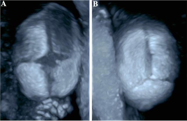
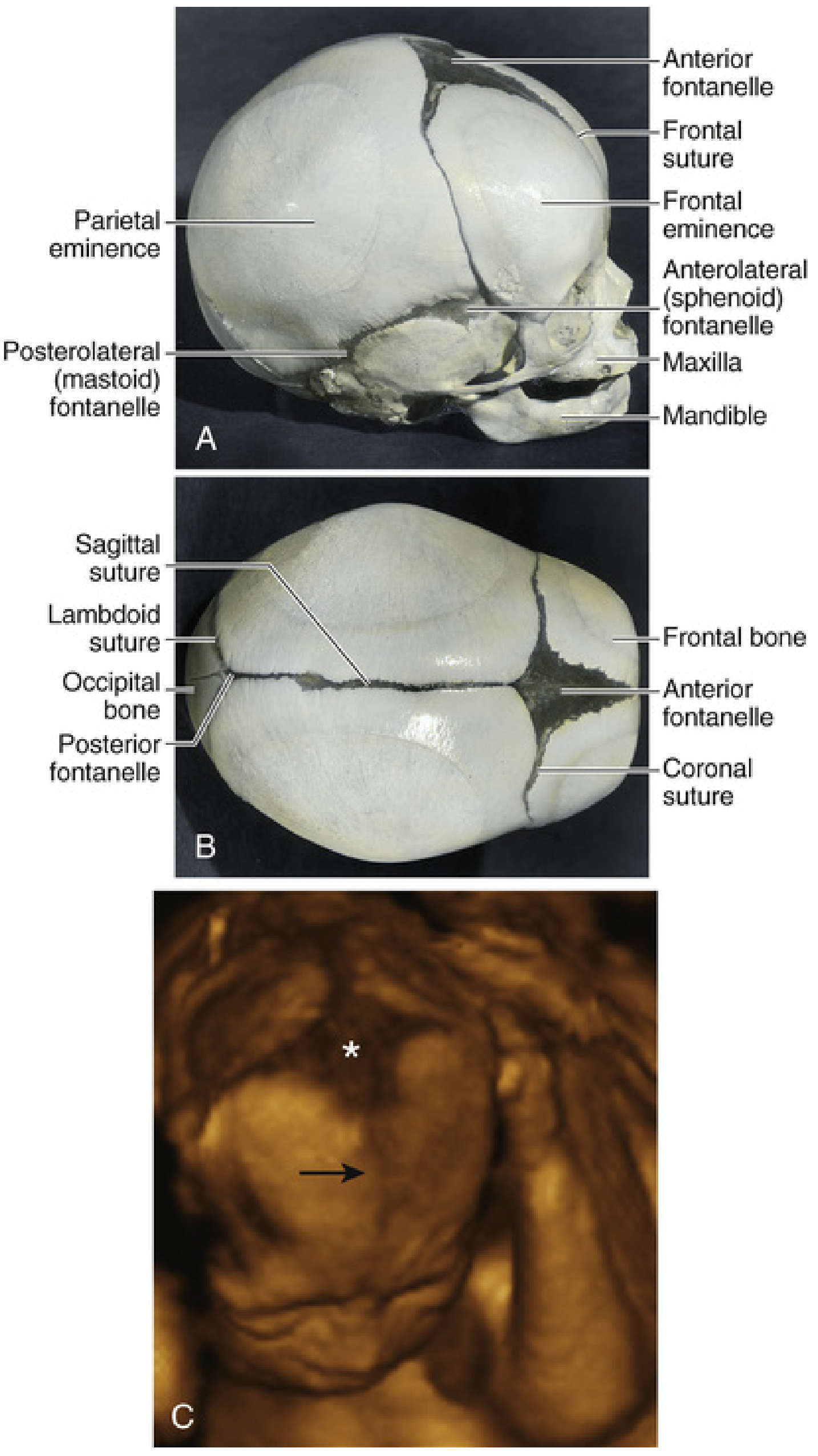
This diagnostic image utilizes 3D ultrasonic skeletal imaging to demonstrate the normal anatomy of a fetal skull in utero. The visualization focuses on the cranial sutures and fontanelles, which appear as hypoechoic linear gaps between the ossified cranial bones. Panel A provides a superior-frontal view, highlighting the anterior fontanelle, a large diamond-shaped gap where the frontal (metopic), sagittal, and bilateral coronal sutures converge. Panel B displays a posterior view of the skull, showing the posterior fontanelle, a smaller triangular space where the sagittal suture meets the bilateral lambdoid sutures. The imaging modality clearly delineates the margins of the frontal, parietal, and occipital bones. This clinical visualization is essential for prenatal screening of syndromic and non-syndromic craniosynostosis, allowing for the assessment of suture patency and the identification of premature fusion or abnormal skull morphology.

This comparative diagnostic image features two axial MRI scans (A and B) illustrating fetal head molding during labor within the maternal pelvis. Scan A (pre-labor) shows a normal, rounded fetal skull contour with continuous alignment between the occipital bone (annotated in red), parietal bones (green), and frontal bones (blue), indicating open sutures and fontanelles. Scan B (second stage of labor) demonstrates significant mechanical deformation as the fetal head descends through the pelvic brim. In scan B, the fetal skull exhibits a characteristic 'sugarloaf' or elongated appearance. Key visual findings include overlapping of the cranial bones: the parietal bone shifts relative to the occipital bone, and the frontal bone overlaps the parietal bone. These changes indicate the closure of the lambdoid and coronal sutures and reduction of the fontanelles to accommodate the birth canal. The image highlights the physiological flexibility of the fetal cranium and provides clinical evidence of head molding dynamics during active childbirth, useful for obstetric and radiological education.
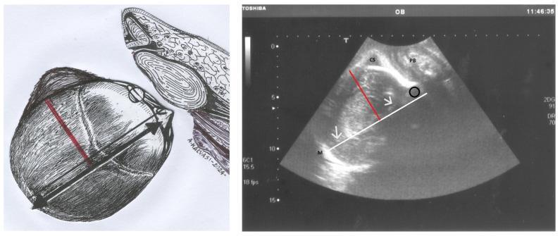
This composite educational graphic illustrates the ultrasonographic assessment of fetal head asynclitism during labor. The left panel shows an anatomical diagram of the fetal skull in a right occiput position, highlighting the sagittal suture and parietal bones relative to the maternal pelvis. The right panel displays a corresponding longitudinal translabial ultrasound image. A white line marks the midline (M) and the hyperechogenic cerebral falx between the hemispheres (indicated by white arrows). The pubic symphysis (PS) and a caput succedaneum (CS) on the left parietal bone are labeled. A red line represents the 'Asynclitism Degree' (AD), measured as the perpendicular distance from the anatomical midline to the sagittal suture. A black circle identifies the 'anterior squint sign,' a sonographic marker of anterior asynclitism where the orbits are misaligned relative to the ultrasound beam. This tool is critical in obstetrics for diagnosing fetal malposition and predicting the likelihood of intrapartum cesarean delivery (ICD) versus successful vaginal birth.
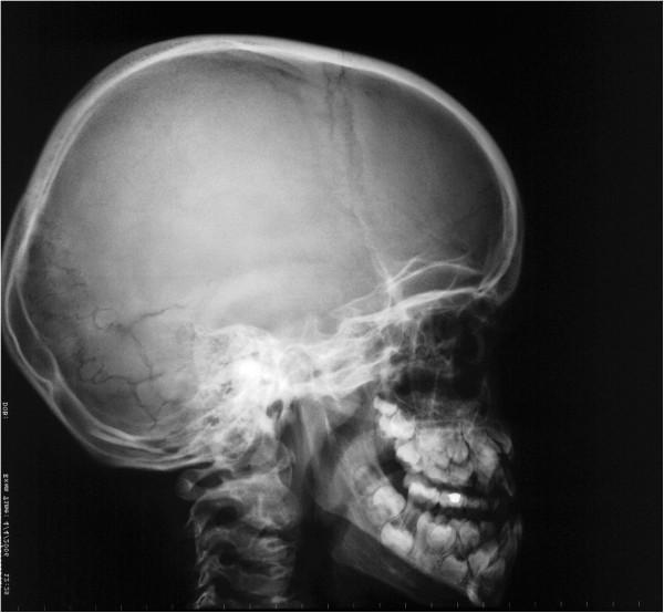
A lateral cephalometric radiograph of the skull illustrating characteristic diagnostic features of cleidocranial dysplasia (CCD). The cranial vault displays open sutures and persistent, large fontanelles, contributing to a bulging calvarium appearance. Numerous Wormian bones—small, irregular accessory bone islands—are prominently visible within the lambdoidal sutures. Facial skeletal findings include marked maxillary hypoplasia and a relatively prognathic mandible, resulting in a skeletal Class III relationship. The dental presentation shows a complex mixed dentition with delayed eruption of permanent teeth, retention of primary teeth, and multiple impacted supernumerary teeth. These radiographic markers are highly representative of a generalized skeletal dysplasia affecting intramembranous bone formation.
female pelvis obstetric diameters inlet outlet anatomy
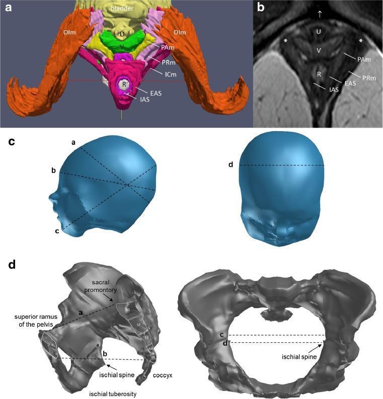
A multi-panel figure illustrating female pelvic anatomy and fetal head dimensions for obstetric study. Panel A: A color-coded 3D inferior view of the Levator Ani Muscle (LAM) complex. Key structures include the obturator internus (orange), puborectal muscle (light purple), iliococcygeus (dark red), and puboanal muscle (yellow). Central visceral structures are labeled: urethra (yellow), vagina (green), and rectum (gray), flanked by the internal (purple) and external (pink) anal sphincters. Panel B: A corresponding axial T2-weighted MRI of the female pelvis confirming the spatial orientation of the urethra (U), vagina (V), and rectum (R), with markers for the pubic bone attachment (asterisk). Panel C: 3D models of a fetal head defining principal obstetric diameters, including suboccipitobregmatic and biparietal dimensions. Panel D: 3D reconstructions of the female bony pelvis in lateral and axial views, marking the pelvic inlet, outlet, and interspinous diameters. This educational figure integrates radiological findings with anatomical modeling to describe pelvic floor relationships relevant to childbirth mechanics.
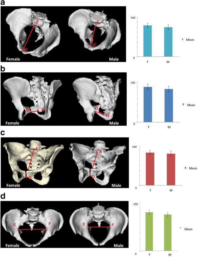
This medical comparison chart utilizes 3D reconstructions and statistical bar graphs to illustrate sexual dimorphism in pelvic inlet measurements between females and males. The content is divided into four sections (a-d), each showcasing a different clinical pelvimetry parameter. Section (a) demonstrates the obstetric conjugate (A-C), showing a greater anteroposterior dimension and a more rounded inlet in the female pelvis. Section (b) displays the true conjugate (D-M), while section (c) shows the diagonal conjugate (A-D), both highlighting the increased pelvic capacity in females. Section (d) visualizes the transverse diameter (E-F), emphasizing the broader, more oval shape of the female pelvic brim compared to the narrower, heart-shaped male inlet. Accompanying bar charts provide quantitative mean differences, confirming that these inlet diameters are significantly larger in the female population. This resource is designed for anatomy and obstetrics education, focusing on the structural adaptations of the female pelvis for childbirth and its comparative morphology against the male pelvis.
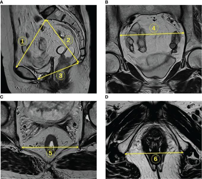
A composite of four T2-weighted magnetic resonance images (MRI) of the human pelvis, demonstrating standardized pelvimetry measurements used for obstetric or surgical assessment. (A) Sagittal section showing three anteroposterior diameters: line 1 (pelvic inlet) from the sacral promontory to the superior pubic symphysis; line 2 (pelvic depth) from the promontory to the tailbone; and line 3 (pelvic outlet) from the inferior pubic symphysis to the tailbone. (B) Coronal section showing line 4, representing the transverse diameter between the iliopectineal lines. (C) Axial section at the level of the mid-pelvis showing line 5, the interspinous distance between the ischial spines. (D) Lower axial section showing line 6, the intertuberous distance between the ischial tuberosities. These diagnostic images utilize the high contrast between low-signal (dark) cortical bone and surrounding soft tissues to define key anatomical landmarks. This material serves as an educational reference for radiological pelvimetry and pelvic anatomy classification.
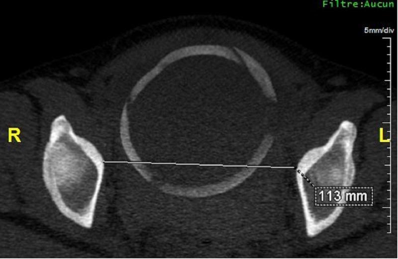
This diagnostic image is an axial Maximum Intensity Projection (MIP) reconstruction from a computed tomography (CT) scanopelvimetry. It provides a cross-sectional view of the female pelvic inlet and outlet for obstetric assessment. The central feature is the sacrum, appearing as an oval bony ring, flanked laterally by the iliac and ischial bones of the pelvis. Orientation is clearly marked with 'R' for the patient's right and 'L' for the patient's left. A linear measurement is demonstrated using a horizontal calliper line connecting the inner margins of the ischial bones. This line measures the median transverse diameter, which is annotated with a numerical value of 113 mm. Technical metadata in the upper right corner indicates a scale of '5mm/div' and the absence of a digital filter ('Filtre: Aucun'). This imaging modality is primarily used in clinical obstetrics to evaluate for pelvic narrowing and assess the adequacy of the birth canal for vaginal delivery.
fetal head diameters suboccipitobregmatic occipitofrontal mento-vertical
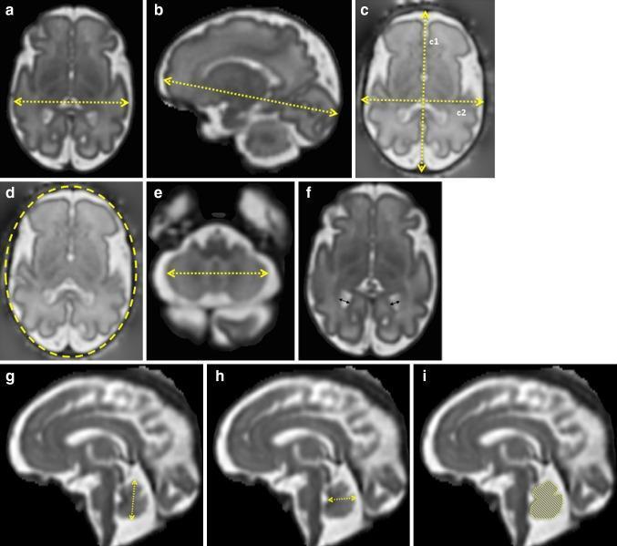
This diagnostic image panel consists of nine fetal magnetic resonance imaging (MRI) views (labeled a-i) demonstrating standardized 2D biometry of the fetal head and brain. The images comprise axial and mid-sagittal planes. Axial views illustrate measurements for the brain biparietal diameter (a), skull occipitofrontal and biparietal diameters (c), head circumference via elliptical tracing (d), transverse cerebellar diameter (e), and atrial diameter of the lateral ventricles (f). Sagittal views focus on the brain fronto-occipital length (b) and posterior fossa structures, specifically the cerebellar vermis. Vermis biometry includes the vertical height (g), width from the fastigium to the posterior border (h), and total cross-sectional area indicated by a shaded overlay (i). Yellow dashed lines and cursors define the measurement axes. This educational resource demonstrates the precise anatomical landmarks and plane orientations required for quantitative fetal neuroimaging assessment, facilitating the monitoring of gestational growth and the detection of central nervous system abnormalities.
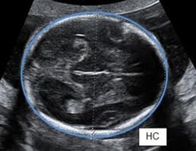
This diagnostic ultrasound image displays an axial cross-section of a fetal head, specifically positioned for biometric assessment. The image demonstrates the standard anatomical plane for measuring Head Circumference (HC) according to ISUOG guidelines. Visible landmarks include the symmetric cerebral hemispheres, the hyperechoic midline falx, and the cavum septum pellucidum. The imaging plane traverses the level of the thalami while specifically excluding the cerebellum to ensure accurate biometry. A blue electronic ellipse is traced around the outer table of the fetal calvaria (skull bone) to calculate the circumference. A vertical dotted line indicates the corresponding biparietal diameter or occipitofrontal diameter axis. The presence of the label 'HC' confirms the educational focus on fetal growth monitoring and obstetrical sonography. This image serves as a clinical example of proper transducer orientation perpendicular to the fetal central axis for standardized prenatal diagnostic measurement.
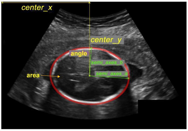
This diagnostic ultrasound image demonstrates a cross-sectional view of a fetal head in the second trimester, a key component of prenatal biometry. The image features a red elliptical overlay used to calculate the Head Circumference (HC), a critical metric for assessing gestational age and fetal growth. The fetal skull is visualized as a bright, hyperechoic curvilinear boundary, while the intracranial contents show characteristic heterogeneous, lower-echo patterns. Geometric annotations illustrate the automated or manual measurement process: 'center_x' and 'center_y' define the spatial coordinates of the head; 'semi_axes_a' and 'semi_axes_b' represent the major and minor radii (biparietal and occipitofrontal diameters); 'angle' denotes the orientation; and 'area' signifies the total surface area within the ellipse. The image contains inherent ultrasound artifacts, including speckle noise and acoustic shadowing. This visual material is primarily used for training in obstetric ultrasonography and the development of automated medical imaging algorithms for fetal health monitoring.
Assignment: Fetal Skull and Pelvis
Subject: Gynecology and Obstetrics
PART I: THE FETAL SKULL
1. Introduction
2. Bones of the Fetal Skull
| Bone | Number | Location |
|---|---|---|
| Frontal (frontal bones) | 2 | Forehead region |
| Parietal bones | 2 | Sides and top of vault |
| Occipital bone | 1 | Back of skull |
| Temporal bones | 2 | Temporal region (squamous part) |
The Developing Human: Clinically Oriented Embryology describes that intramembranous ossification occurs in the head mesenchyme at the sides and top of the brain to form the calvaria. During fetal life, the flat bones are separated by dense connective tissue membranes forming fibrous joints - the sutures of the calvaria (p. 924).
3. Sutures of the Fetal Skull
- They allow molding during delivery
- They help identify fetal position during vaginal examination
| Suture | Location | Bones Separated |
|---|---|---|
| Sagittal suture | Midline, AP direction | Two parietal bones |
| Frontal (metopic) suture | Midline, frontal | Two frontal bones |
| Coronal suture | Transverse, across vertex | Frontal + parietal bones |
| Lambdoid suture | Posterior, V-shaped | Occipital + parietal bones |
| Squamosal sutures | Lateral | Temporal + parietal bones |
4. Fontanelles of the Fetal Skull
4.1 Anterior Fontanelle (Bregma)
- Shape: Diamond/rhombus-shaped
- Location: Junction of sagittal, coronal, and frontal sutures
- Size: ~3-4 cm x 2-3 cm
- Closes: 18 months after birth
- Clinical importance: Largest fontanelle; used to assess fetal position (occiput anterior/posterior); can detect raised intracranial pressure
4.2 Posterior Fontanelle (Lambda)
- Shape: Small, triangular
- Location: Junction of sagittal and lambdoid sutures
- Closes: 6-8 weeks after birth
- Clinical importance: Identifies vertex presentation during labor
4.3 Two Anterolateral (Sphenoidal/Pterion) Fontanelles
- Located at the junction of frontal, parietal, temporal, and sphenoid bones
- Close within 3 months of birth
4.4 Two Posterolateral (Mastoid/Asterion) Fontanelles
- Located at the junction of parietal, occipital, and temporal bones
- Close within 12 months of birth
During molding of the fetal cranium, the frontal bones become flattened, the occipital bone is lengthened, and one parietal bone slightly overrides the other. The cranium returns to its normal shape within a few days after birth (The Developing Human, p. 924-925).
5. Regions (Regions/Areas) of the Fetal Skull
- Vertex - bounded by the anterior fontanelle (bregma), posterior fontanelle (lambda), and the two parietal eminences. This is the most favorable presenting part.
- Sinciput (Brow) - region between the root of the nose and bregma
- Occiput - region behind the posterior fontanelle/lambdoid sutures
- Face - below the root of the nose to the chin (mentum)
6. Landmarks of the Fetal Skull
| Landmark | Description |
|---|---|
| Bregma | Anterior fontanelle |
| Lambda | Posterior fontanelle |
| Brow | Between nasion and bregma |
| Occiput | Posterior part of skull |
| Mentum (Chin) | Lower jaw |
| Nasion | Root of nose |
| Glabella | Between the eyebrows |
| Suboccipital protuberance | Junction of occiput and neck |
7. Diameters of the Fetal Skull
7.1 Antero-Posterior (Longitudinal) Diameters
| Diameter | From | To | Measurement | Presentation |
|---|---|---|---|---|
| Suboccipitobregmatic (SOB) | Suboccipital protuberance | Bregma | ~9.5 cm | Fully flexed vertex (most favorable) |
| Suboccipitofrontal (SOF) | Suboccipital protuberance | Frontal eminence | ~10 cm | Partially flexed vertex |
| Occipitofrontal (OF) | Occipital protuberance | Glabella/root of nose | ~11.5 cm | Deflexed vertex (military attitude) |
| Occipitomental (OM) | Occipital protuberance | Mentum (chin) | ~13.5 cm | Brow presentation |
| Submentovertical | Chin | Vertex | ~11.5 cm | Face presentation (partially extended) |
| Submentobregmatic | Below chin | Bregma | ~9.5 cm | Face presentation (fully extended) |
| Mentovertical | Chin | Vertex | ~13.5 cm | Brow presentation |
7.2 Transverse Diameters
| Diameter | Measurement | Description |
|---|---|---|
| Biparietal diameter (BPD) | ~9.5 cm | Widest transverse diameter; between parietal eminences |
| Bitemporal diameter | ~8 cm | Between the two temporal bones |
7.3 Circumferences
| Circumference | Measurement | Associated with |
|---|---|---|
| Suboccipitobregmatic | ~28 cm | Vertex presentation (flexed) |
| Occipitofrontal | ~34 cm | Deflexed vertex |
| Occipitomental | ~35 cm | Brow presentation |
8. Molding
- Mechanism: The skull bones overlap at the sutures and fontanelles under pressure
- Degree: Depends on duration and force of labor
- Normal molding: One bone overrides the other but reduces within 24-48 hours
- Abnormal/excessive molding: Prolonged labor, cephalopelvic disproportion - can cause tentorial tears, intracranial hemorrhage
- Assessment: Assessed clinically during vaginal examination; graded 0 to +++
9. Caput Succedaneum vs Cephalohematoma
| Feature | Caput Succedaneum | Cephalohematoma |
|---|---|---|
| Definition | Edema of scalp soft tissues | Subperiosteal hemorrhage |
| Timing | Present at birth | Appears after birth (hours) |
| Crosses sutures | Yes | No (limited by periosteum) |
| Resolution | Within 24-48 hours | Weeks to months |
| Cause | Pressure on presenting part | Birth trauma |
PART II: THE OBSTETRIC PELVIS
1. Introduction
2. Bony Pelvis - Composition
- Two hip bones (innominate bones) - each formed by the ilium, ischium, and pubis
- Sacrum - five fused sacral vertebrae
- Coccyx - four fused coccygeal vertebrae
- Sacroiliac joints (bilateral) - slightly mobile in pregnancy
- Pubic symphysis - fibrocartilaginous; softens during pregnancy under the influence of relaxin
- Sacrococcygeal joint - allows coccyx to move posteriorly during delivery
3. The True Pelvis vs False Pelvis
| Feature | False (Greater) Pelvis | True (Lesser) Pelvis |
|---|---|---|
| Location | Above the pelvic brim | Below the pelvic brim |
| Bounded by | Iliac fossae, lumbar vertebrae | Inlet, outlet, walls |
| Obstetric importance | Supports pregnant uterus | Forms the birth canal |
4. Planes of the True Pelvis
4.1 Pelvic Inlet (Brim)
- Bounded anteriorly by the pubic symphysis upper border, laterally by the iliopectineal lines, and posteriorly by the sacral promontory
- Shape: Transversely oval (in gynecoid pelvis)
4.2 Plane of Greatest Dimensions
- Level of mid-pelvis
- Roomiest part of the birth canal
4.3 Plane of Least Dimensions (Mid-Pelvis)
- Level of ischial spines
- Most narrow part - most common site of arrest of labor
4.4 Pelvic Outlet
- Bounded anteriorly by the pubic arch, laterally by ischial tuberosities and sacrotuberous ligaments, posteriorly by the coccyx
5. Diameters of the Pelvis
5.1 Diameters of the Pelvic Inlet
| Diameter | Measurement | Description |
|---|---|---|
| True (Obstetric) Conjugate | ~11 cm | Narrowest AP diameter; from sacral promontory to POSTERIOR surface of pubic symphysis - the most important diameter |
| Anatomical Conjugate (Vera) | ~11.5 cm | From sacral promontory to UPPER border of pubic symphysis |
| Diagonal Conjugate | ~12.5 cm | From sacral promontory to LOWER border of symphysis pubis - the only clinically measurable conjugate |
| Transverse diameter | ~13 cm | Widest transverse diameter between iliopectineal lines |
| Oblique diameters | ~12 cm | From sacroiliac joint to opposite iliopectineal eminence |
Clinical note: The obstetric conjugate = Diagonal conjugate - 1.5 cm (Approximate formula)
5.2 Diameters of the Mid-Pelvis
| Diameter | Measurement |
|---|---|
| Interspinous diameter | ~10.5 cm (smallest diameter; most important at mid-pelvis) |
| Anteroposterior diameter | ~12 cm |
| Posterior sagittal diameter | ~4.5 cm |
5.3 Diameters of the Pelvic Outlet
| Diameter | Measurement |
|---|---|
| Intertuberous diameter | ~11 cm (transverse - most important) |
| Anteroposterior diameter | ~9.5-11.5 cm (from lower symphysis to tip of coccyx; increases to 13.5 cm with coccyx displacement) |
| Posterior sagittal diameter | ~7.5 cm |
6. Caldwell-Moloy Classification of Pelvic Types
| Type | Incidence (Females) | Inlet Shape | Obstetric Outcome |
|---|---|---|---|
| Gynecoid | ~50% | Rounded/transversely oval | Most favorable for vaginal delivery |
| Android | ~25% | Heart-shaped/triangular (male-type) | Unfavorable; prone to arrest |
| Anthropoid | ~25% | AP oval (longer AP than transverse) | Favors OP position; vaginal delivery possible |
| Platypelloid | ~5% | Flat/transversely wide, short AP | Difficult delivery; transverse arrest common |
Mixed types are common and are named by combining the posterior and anterior segments (e.g., "gynecoid-android").
7. Axis of the Pelvis
- Downward and backward through the inlet
- Downward through the cavity
- Downward and forward through the outlet
8. Inclination of the Pelvis
- The pelvic inlet makes an angle of approximately 55-60° with the horizontal
- The anterior superior iliac spines and pubic tubercles lie in the same vertical plane
- The sacral promontory projects anteriorly
9. The Pelvic Floor
- Levator ani muscles (pubococcygeus, iliococcygeus, puborectalis)
- Coccygeus muscle
- Perineal body - a key fibromuscular structure between vagina and anus
- Directs the fetal head anteriorly (causing internal rotation)
- Is stretched and may tear (causing perineal lacerations)
10. Pelvimetry
- Clinical pelvimetry - digital vaginal examination to measure diagonal conjugate, assess ischial spines, subpubic angle, sacrum curvature
- X-ray pelvimetry - largely abandoned due to radiation risk
- CT pelvimetry - more accurate, lower radiation
- MRI pelvimetry - most accurate, no radiation; used in special cases
- Diagonal conjugate > 11.5 cm
- Interspinous diameter > 10 cm
- Intertuberous diameter > 8 cm
- Subpubic angle > 90° (obtuse in female pelvis)
PART III: RELATIONSHIP BETWEEN FETAL SKULL AND MATERNAL PELVIS
1. Engagement
2. Mechanisms of Labor (Cardinal Movements)
- Engagement - BPD at or below pelvic inlet
- Descent - progressive downward movement
- Flexion - chin on chest; SOB diameter (9.5 cm) presents
- Internal rotation - occiput rotates to pubic symphysis (anterior)
- Extension - head extends under pubic arch at outlet
- Restitution - head rotates back to original position
- External rotation - shoulders rotate to AP diameter
- Expulsion - delivery of shoulders and body
3. Clinical Significance of Skull-Pelvis Relationship
| Situation | Clinical Implication |
|---|---|
| Cephalopelvic disproportion (CPD) | Fetal head too large OR pelvis too small; requires cesarean section |
| Asynclitism | Sagittal suture not in midline of inlet; anterior or posterior asynclitism |
| Deep transverse arrest | Fetal head arrests at mid-pelvis with transverse position of sagittal suture |
| Occipito-posterior position | Occiput directed posteriorly; prolonged labor, increased molding |
| Brow presentation | Largest diameter (13.5 cm) presents; vaginal delivery usually impossible |
| Face presentation | Mentovertical diameter presents; only anterior face can deliver vaginally |
Summary Table: Key Obstetric Diameters
| Structure | Diameter | Measurement |
|---|---|---|
| Fetal skull | Suboccipitobregmatic | 9.5 cm |
| Biparietal | 9.5 cm | |
| Occipitofrontal | 11.5 cm | |
| Occipitomental | 13.5 cm | |
| Pelvic inlet | Obstetric (true) conjugate | 11 cm |
| Transverse | 13 cm | |
| Diagonal conjugate | 12.5 cm | |
| Mid-pelvis | Interspinous | 10.5 cm |
| Pelvic outlet | Intertuberous | 11 cm |
References
- Moore KL, Persaud TVN, Torchia MG. The Developing Human: Clinically Oriented Embryology. 11th ed. Elsevier; 2020. (Membranous Neurocranium, p. 923-925)
- Resnik R, Lockwood CJ, et al. Creasy & Resnik's Maternal-Fetal Medicine: Principles and Practice. 8th ed. Elsevier; 2019.
- Tintinalli JE, et al. Tintinalli's Emergency Medicine: A Comprehensive Study Guide. 9th ed. McGraw-Hill; 2020. (Mechanisms of labor, vertex presentation)
- Cunningham FG, et al. Williams Obstetrics. 25th ed. McGraw-Hill; 2018.