
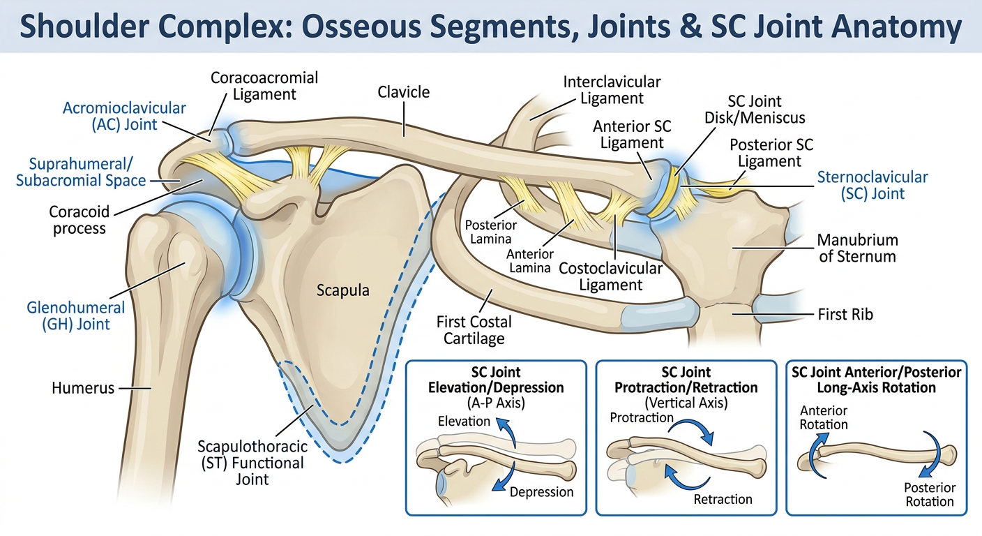
Components of the Shoulder Complex The osseous segments of the shoulder complex are the clavicle, scapula, and humerus (Fig. 7-1). These three segments are joined by three interdependent linkages: the SC joint, the acromioclavicular (AC) joint, and the GH joint. The articulation between the scapula and the thorax is often described as the scapulothoracic (ST) “joint,” although it does not have the characteristics of a fibrous, cartilaginous, or synovial union. Instead, scapular motion on the thorax is directly a function of SC, AC, or combined SC and AC joint motion. The ST joint is frequently described in the literature as a “functional” joint. An additional functional articulation that is, at times, considered to be part of the shoulder complex is the subacromial (or suprahumeral) “joint.” This functional joint is formed by movement of the head of the humerus below the coracoacromial arch. Although the movement between these two components plays an important role in shoulder function and dysfunction, we will refer to it as the suprahumeral space and consider it a component of the GH joint rather than a separate linkage. The joints that compose the shoulder complex in combination with trunk motion can contribute as much as 180 of elevation to the upper extremity. Elevation of the upper extremity refers to the combination of scapular, clavicular, and humeral motion that occurs when the arm is raised either forward or to the side (including sagittal plane flexion, frontal plane abduction, and all the motions in between). Motion of the scapula on the thorax normally contributes about one third of the total motion necessary for elevation of the arm through the linked SC and AC joint motions, whereas the GH joint contributes about two thirds of the total motion. Although integrated function of all three joints is of primary interest, each of the articulations and components of the shoulder complex must be examined individually before integrated dynamic function can be appreciated. Sternoclavicular Joint The SC joint serves as the only structural attachment of the clavicle, scapula, and upper extremity to the axial skeleton. Movement of the clavicle at the SC joint inevitably produces movement of the scapula under conditions of normal function, because the scapula is attached to the lateral end of the clavicle. In order for the scapula to not move with the clavicle during SC motion, equal and opposite motions would have to occur at the AC joint; this is not typical with an intact claviculoscapular linkage. Similarly, any motions of the scapula must result in motion at the SC joint (unless scapular motions are isolated to the AC joint—which is, again, unlikely under normal circumstances). The SC joint is a plane synovial joint with three rotatory and three translatory degrees of freedom. This joint has a synovial capsule, a joint disk, and three major ligaments. ■ Sternoclavicular Articulating Surfaces The SC articulation consists of two saddle-shaped surfaces, one at the sternal or medial end of the clavicle and one at the notch formed by the manubrium of the sternum and first costal cartilage (Fig. 7-2). Because tremendous individual differences exist across people and the saddle shape of these surfaces is very subtle, the SC joint is often classified as a plane synovial joint. The sternal end of the clavicle and the manubrium are incongruent; that is, there is little contact between their articular surfaces. The superior portion of the medial clavicle does not contact the manubrium at all; instead it serves as the attachment for the SC joint disk and the interclavicular ligament. At rest, the SC joint space is wedge-shaped and open superiorly.2 Movements of the clavicle in relation to the manubrium result in changes to the areas of contact between the clavicle, the SC joint disk, and the manubriocostal cartilage. ■ Sternoclavicular Disk As is generally true at an incongruent joint, the SC joint has a fibrocartilage joint disk, or meniscus, that increases congruence between joint surfaces. The upper portion of the SC disk is attached to the posterosuperior clavicle. The lower portion is attached to the manubrium and first costal cartilage, as well as to the anterior and posterior aspects to the fibrous capsule.3 The disk diagonally transects the SC joint space (Fig. 7-3) and divides the joint into two separate cavities.1 Given its attachments, the disk acts like a hinge or pivot point during clavicle motion. In elevation and depression of the clavicle, the medial end of the clavicle rolls and slides on the relatively stationary disk, with the upper attachment of the disk serving as a pivot point. In protraction/retraction of the clavicle, the SC disk and medial clavicle roll and slide together on the manubrial facet, with the lower attachment of the disk serving as a pivot point.1 The disk, therefore, is considered part of the manubrium in elevation/depression and part of the clavicle in protraction/retraction. As the disk switches its participation from one articular segment to the other during clavicular motions, mobility between the segments is maintained and stability is enhanced. The resultant movement of the clavicle in both elevation/depression and protraction/retraction is a fairly complex set of motions, with the mechanical axis for these two movements located not at the SC joint itself but at the more laterally located costoclavicular ligament (see Fig. 7-3). The SC disk serves an important stability function by increasing joint congruence and absorbing forces that may be transmitted along the clavicle from its lateral end. In Figure 7-3, it can be seen that the unique diagonal attachment of the SC disk will check medial movement of the clavicle that might otherwise cause the large medial articular surface of the clavicle to override the shallow manubrial facet. The disk also has substantial contact with the medial clavicle, permitting the disk to dissipate the medially directed forces that would otherwise cause high pressure at the small manubrial facet. Although one might think that medially directed forces on the clavicle are rare, we shall see that this is not the case when we examine the function of the AC joint, the upper trapezius muscle, and the coracoclavicular ligament. Continuing Exploration: Three-Compartment SC Joint Anatomic examination of the SC articulation has led to the proposal that there are three, rather than two, functional units of the SC joint: a lateral compartment between the disk and clavicle for elevation and depression; a medial compartment between the disk and manubrium for protraction and retraction; and a costoclavicular joint for anterior and posterior long axis rotation. Anterior and posterior rotation are thought to occur between a portion of the disk over the first rib and a “conus” on the anteroinferior edge of the articular surface of the medial clavicle.4 ■ Sternoclavicular Joint Capsule and Ligaments The SC joint is surrounded by a fairly strong fibrous capsule but must depend on three ligaments for the majority of its support. These are the sternoclavicular ligaments, the costoclavicular ligament, and the interclavicular ligament (Fig. 7-4). The anterior and posterior SC ligaments reinforce the capsule and function primarily to check anterior and posterior translatory movement of the medial end of the clavicle. The costoclavicular ligament is a very strong ligament found between the clavicle and the first rib. The costoclavicular ligament has two segments or laminae. The anterior lamina has fibers directed laterally from the first rib to the clavicle, whereas the fibers of the posterior lamina are directed medially from the rib to the clavicle.3,5 Both segments check elevation of the lateral end of the clavicle and, when the limits of the ligament are reached, may contribute to the inferior gliding of the medial clavicle that occurs with clavicular elevation.6 The costoclavicular ligament is also positioned to counter the superiorly directed forces applied to the clavicle by the sternocleidomastoid and sternohyoid muscles. The medially directed fibers of the posterior lamina will resist medial movement of the clavicle,7 absorbing some of the force that would otherwise be imposed on the SC disk. The interclavicular ligament resists excessive depression of the distal clavicle and superior glide of the medial end of the clavicle. The limitation to clavicular depression is critical to protecting structures such as the brachial plexus and subclavian artery that pass under the clavicle and over the first rib. In fact, when the clavicle is depressed and the interclavicular ligament and superior capsule are taut, the tension in the interclavicular ligament can support the weight of the upper extremity.8 ■ Sternoclavicular Motions The three rotatory degrees of freedom at the SC joint are most commonly described as elevation/depression, protraction/retraction, and anterior/posterior rotation of the clavicle. Motions of any joint are typically described by identifying the direction of movement of the portion of the lever that is farthest from the joint. The horizontal alignment of the clavicle (rather than the vertical alignment of most of the appendicular levers of the skeleton) can sometimes create confusion and impair visualization of the clavicular motions. The motions of elevation/depression (Fig. 7-5) and protraction/retraction (Fig. 7-6) should be visualized by referencing movement of the lateral end of the clavicle. Clavicular anterior/posterior rotation are long axis rolling motions of the entire clavicle (Fig. 7-7). Three degrees of translatory motion at the SC joint can also occur, although they are very small in magnitude. Translations of the medial clavicle on the manubrium are usually defined as occurring in anterior/posterior, medial/lateral, and superior/inferior directions (see Figs. 7-5 and 7-6). Elevation and Depression of the Clavicle The motions of elevation and depression occur around an approximately anteroposterior (A-P) axis (see Fig. 7-5) between a convex clavicular surface and a concave surface formed by the manubrium and the first costal cartilage. With elevation, the lateral clavicle rotates upward, and with depression, the lateral clavicle rotates downward. The cephalocaudal shape of the articular surfaces and the location of the axis indicate that the convex surface of the clavicle must slide inferiorly on the concave manubrium and first costal cartilage, in a direction opposite to movement of the lateral end of the clavicle. The SC joint axis is described as lying lateral to the joint at the costoclavicular ligament. The location of this functional (rather than anatomic) axis relatively far from the joint reflects a large intraarticular motion of the medial clavicle. The range of available clavicular elevation has been described as upto 48 , whereas passive depression is limited, on average, to less than 15 . 9 The full magnitude of the available range of elevation is generally not utilized during functional ranges of arm elevation.10,11 Protraction and Retraction of the Clavicle Protraction and retraction of the clavicle occur at the SC joint around an approximately vertical (superoinferior) axis that also appears to lie at the costoclavicular ligament (see Fig. 7-6). With protraction, the lateral clavicle rotates anteriorly, and with retraction, the lateral clavicle rotates posteriorly. The configuration of joint surfaces in this plane is the opposite of that for elevation/depression; the medial end of the clavicle is concave, and the manubrial side of the joint is convex. During protraction, the medial clavicle is expected to slide anteriorly on the manubrium and first costal cartilage. There is about 15 to 20 protraction and 20 to 30 retraction of the clavicle available.9,11,12 Anterior and Posterior Rotation of the Clavicle Anterior/posterior, or long axis, rotation of the clavicle (see Fig. 7-7) occurs as a spin between the saddleshaped surfaces of the medial clavicle and manubriocostal facet. Unlike many joints that can rotate in either direction from resting position of the joint, the clavicle rotates primarily in only one direction from its resting position. The clavicle rotates posteriorly from neutral, bringing the inferior surface of the clavicle to face anteriorly. This has also been referred to as backward or upward rotation rather than posterior rotation.1 From its fully rotated position, the clavicle can rotate anteriorly again to return to neutral. Available anterior rotation past neutral is very limited, generally described as less than 10 . 1 The range of available clavicular posterior rotation is cited to be as much as 50 . 10 The axis of rotation runs longitudinally
What would you like me to do with this passage?
What kind of visual would be most useful?
Detailed anatomical diagram of the shoulder complex showing all key structures from a kinesiology/biomechanics perspective. Label the following bones: clavicle, scapula, humerus, manubrium of sternum, first costal cartilage, and first rib. Label the following joints: Sternoclavicular (SC) joint, Acromioclavicular (AC) joint, Glenohumeral (GH) joint, Scapulothoracic (ST) functional joint, and the Suprahumeral/Subacromial space with the coracoacromial arch. Label ligaments including: anterior and posterior SC ligaments, costoclavicular ligament (with anterior and posterior laminae indicated), interclavicular ligament, and the SC joint disk/meniscus. Include arrows or inset panels showing the three SC joint motions: elevation/depression (around an A-P axis), protraction/retraction (around a vertical axis), and anterior/posterior long-axis rotation. Use clean medical illustration style with clear color coding for bones (light beige), ligaments (yellow), and joints (blue highlight). White background, educational poster format with a title at the top reading "Shoulder Complex: Osseous Segments, Joints & SC Joint Anatomy".
Grid system definition
- Columns - vertical divisions that content snaps to
- Rows - horizontal divisions
- Gutters - spacing between columns
- Margins - space between the grid and the edge of the page/screen
- Baseline grid - evenly spaced horizontal lines for aligning text
For electrotherapy
grid system electrotherapy definition electrode placement
grid system definition electrotherapy physical therapy modality textbook
"grid system" interferential current IFC electrotherapy definition quadrant
Grid System in Electrotherapy - Definition
Key Features
- Functional Electrical Stimulation (FES) for targeted finger flexion/extension
- TENS for precise sensory nerve coverage
- NMES for motor point location in partially paralyzed muscles
Clinical Relevance
| Context | How the Grid Is Used |
|---|---|
| FES / NMES | Identifies motor points - spots on the skin overlying the nerve entry point of a muscle where the lowest current threshold produces the strongest, most selective contraction |
| TENS | Maps the area of pain/paresthesia to select the best placement for pain coverage |
| Interferential Current (IFC) | Guides placement of the 4-electrode "quadrant" pattern around the target tissue |
| Acupuncture-point stimulation | Some protocols use a grid to locate electro-acupuncture points systematically |
Summary
Grid system electrotherapy write definition, advantage, indication, contraindications, physiology effect add wiring of house with distribution light and power circuit
What format would you like the output in? · For the wiring section — is this a combined assignment where electrotherapy AND house wiring are separate topics in the same document?
grid system electrotherapy definition advantages indications contraindications physiological effects
https://www.electrotherapy.org/faqs
mkdir -p /home/daytona/workspace/grid-electrotherapy
~/grid-electrotherapy/build.js
const pptxgen = require("pptxgenjs");

const pres = new pptxgen();
pres.layout = "LAYOUT_16x9";
pres.title = "Grid System in Electrotherapy";

// ── COLOR PALETTE ──────────────────────────────────────────────
const C = {
  navyDark:  "0A1628",   // dominant dark background
  navy:      "0D2145",   // section headers / dark panels
  teal:      "1A7F8E",   // accent 1
  cyan:      "29C4D8",   // accent 2 / highlights
  gold:      "F5A623",   // warning / contraindication
  red:       "E84040",   // danger
  green:     "2ECC71",   // positive / indication
  white:     "FFFFFF",
  offWhite:  "F0F4F8",
  lightGray: "D6E4EC",
  mid:       "6B8FAB",
};

// ── HELPER: add slide background ──────────────────────────────
function darkSlide(pres) {
  const s = pres.addSlide();
  s.background = { color: C.navyDark };
  return s;
}
function lightSlide(pres) {
  const s = pres.addSlide();
  s.background = { color: C.offWhite };
  return s;
}

// ── HELPER: accent bar at top ─────────────────────────────────
function topBar(slide, color) {
  slide.addShape(pres.ShapeType.rect, { x: 0, y: 0, w: 10, h: 0.12, fill: { color } });
}

// ══════════════════════════════════════════════════════════════
// SLIDE 1 — TITLE
// ══════════════════════════════════════════════════════════════
{
  const s = darkSlide(pres);

  // decorative blocks
  s.addShape(pres.ShapeType.rect, { x: 0, y: 0, w: 3.8, h: 5.625, fill: { color: C.navy }, line: { color: C.navy } });
  s.addShape(pres.ShapeType.rect, { x: 3.6, y: 0, w: 0.18, h: 5.625, fill: { color: C.teal }, line: { color: C.teal } });
  s.addShape(pres.ShapeType.rect, { x: 3.78, y: 0, w: 0.06, h: 5.625, fill: { color: C.cyan }, line: { color: C.cyan } });

  // grid icon (dots)
  const dots = [[0.6,1.1],[1.2,1.1],[1.8,1.1],[2.4,1.1],
                [0.6,1.7],[1.2,1.7],[1.8,1.7],[2.4,1.7],
                [0.6,2.3],[1.2,2.3],[1.8,2.3],[2.4,2.3],
                [0.6,2.9],[1.2,2.9],[1.8,2.9],[2.4,2.9]];
  dots.forEach(([x,y]) => {
    s.addShape(pres.ShapeType.ellipse, { x, y, w: 0.14, h: 0.14, fill: { color: C.cyan }, line: { color: C.cyan } });
  });

  // title text
  s.addText("GRID SYSTEM", { x: 4.1, y: 0.9, w: 5.6, h: 0.85,
    fontSize: 40, bold: true, color: C.white, fontFace: "Calibri", charSpacing: 3 });
  s.addText("IN ELECTROTHERAPY", { x: 4.1, y: 1.75, w: 5.6, h: 0.75,
    fontSize: 28, bold: true, color: C.cyan, fontFace: "Calibri", charSpacing: 2 });

  s.addShape(pres.ShapeType.rect, { x: 4.1, y: 2.6, w: 4.5, h: 0.04, fill: { color: C.teal }, line: { color: C.teal } });

  s.addText("Definition  •  Advantages  •  Indications\nContraindications  •  Physiological Effects", {
    x: 4.1, y: 2.75, w: 5.6, h: 0.9,
    fontSize: 13, color: C.lightGray, fontFace: "Calibri", italic: true
  });

  s.addText("Physical Therapy & Rehabilitation", {
    x: 4.1, y: 4.8, w: 5.6, h: 0.45,
    fontSize: 12, color: C.mid, fontFace: "Calibri"
  });
}

// ══════════════════════════════════════════════════════════════
// SLIDE 2 — DEFINITION
// ══════════════════════════════════════════════════════════════
{
  const s = lightSlide(pres);
  topBar(s, C.teal);

  s.addShape(pres.ShapeType.rect, { x: 0, y: 0.12, w: 10, h: 0.88, fill: { color: C.navy }, line: { color: C.navy } });
  s.addText("DEFINITION", { x: 0.4, y: 0.18, w: 9, h: 0.72,
    fontSize: 26, bold: true, color: C.white, fontFace: "Calibri", charSpacing: 2 });

  // large definition box
  s.addShape(pres.ShapeType.rect, { x: 0.3, y: 1.2, w: 9.4, h: 1.55,
    fill: { color: C.navy }, line: { color: C.teal, pt: 1.5 }, rectRadius: 0.08 });
  s.addText(
    "The Grid System in electrotherapy is a structured, coordinate-based electrode placement methodology that divides a body segment into a matrix of equally spaced rows and columns of points. " +
    "Each point on the grid is a candidate electrode placement site. The clinician systematically scans through these points using electrical stimulation to identify the precise location " +
    "that produces the most effective, selective, and reproducible therapeutic response.",
    { x: 0.5, y: 1.3, w: 9.0, h: 1.35,
      fontSize: 13.5, color: C.white, fontFace: "Calibri", align: "left", valign: "middle" }
  );

  // three key concept boxes
  const boxes = [
    { x: 0.3,  label: "COORDINATE\nFRAMEWORK", body: "Anchored to anatomical landmarks (e.g. elbow crease to wrist crease). Scaled to patient anatomy.", color: C.teal },
    { x: 3.65, label: "SYSTEMATIC\nSCANNING",   body: "Therapist scans each grid point during stimulation to assess motor or sensory response at each site.", color: C.cyan },
    { x: 7.0,  label: "PRECISION\nDOCUMENTATION", body: "Optimal sites are marked or recorded for consistent, reproducible electrode placement across sessions.", color: C.gold },
  ];
  boxes.forEach(b => {
    s.addShape(pres.ShapeType.rect, { x: b.x, y: 2.95, w: 3.15, h: 2.35,
      fill: { color: C.navy }, line: { color: b.color, pt: 1.5 }, rectRadius: 0.08 });
    s.addText(b.label, { x: b.x + 0.1, y: 3.0, w: 2.95, h: 0.65,
      fontSize: 11.5, bold: true, color: b.color, fontFace: "Calibri", align: "center" });
    s.addShape(pres.ShapeType.rect, { x: b.x + 0.15, y: 3.65, w: 2.85, h: 0.03,
      fill: { color: b.color }, line: { color: b.color } });
    s.addText(b.body, { x: b.x + 0.1, y: 3.72, w: 2.95, h: 1.45,
      fontSize: 11, color: C.lightGray, fontFace: "Calibri", align: "center", valign: "top" });
  });
}

// ══════════════════════════════════════════════════════════════
// SLIDE 3 — ADVANTAGES
// ══════════════════════════════════════════════════════════════
{
  const s = darkSlide(pres);
  topBar(s, C.green);

  s.addShape(pres.ShapeType.rect, { x: 0, y: 0.12, w: 10, h: 0.88, fill: { color: "112E1A" }, line: { color: "112E1A" } });
  s.addText("ADVANTAGES", { x: 0.4, y: 0.18, w: 9, h: 0.72,
    fontSize: 26, bold: true, color: C.white, fontFace: "Calibri", charSpacing: 2 });

  const advs = [
    { icon: "01", title: "Precision Electrode Placement",
      body: "Removes guesswork by using a coordinate system. Electrodes are placed at anatomically determined, patient-specific optimal sites." },
    { icon: "02", title: "Reproducibility Across Sessions",
      body: "Mapped grid points allow the exact same electrode positions to be used in every subsequent treatment session, ensuring consistent dosing." },
    { icon: "03", title: "Selective Muscle / Nerve Targeting",
      body: "Especially valuable in FES/NMES — identifies motor points where the lowest current produces the strongest, most isolated contraction." },
    { icon: "04", title: "Adaptable to Individual Anatomy",
      body: "Grid spacing scales to each patient's limb length and circumference, making it applicable across patients of varying body sizes." },
    { icon: "05", title: "Minimises Patient Discomfort",
      body: "By finding the most responsive site, the required current amplitude can be lowered, reducing skin irritation and discomfort." },
    { icon: "06", title: "Facilitates Clinical Research",
      body: "Standardised placement coordinates enable comparison of results across patients and studies, improving evidence quality." },
  ];

  const cols = [[0.3, 1.15], [3.55, 1.15], [6.8, 1.15],
                [0.3, 3.15], [3.55, 3.15], [6.8, 3.15]];
  advs.forEach((a, i) => {
    const [x, y] = cols[i];
    s.addShape(pres.ShapeType.rect, { x, y, w: 3.0, h: 1.85,
      fill: { color: "112E1A" }, line: { color: C.green, pt: 1 }, rectRadius: 0.07 });
    s.addShape(pres.ShapeType.rect, { x, y, w: 0.42, h: 1.85,
      fill: { color: C.green }, line: { color: C.green }, rectRadius: 0.07 });
    s.addText(a.icon, { x: x + 0.02, y: y + 0.65, w: 0.38, h: 0.55,
      fontSize: 14, bold: true, color: C.navyDark, fontFace: "Calibri", align: "center" });
    s.addText(a.title, { x: x + 0.5, y: y + 0.05, w: 2.42, h: 0.45,
      fontSize: 10.5, bold: true, color: C.green, fontFace: "Calibri" });
    s.addText(a.body, { x: x + 0.5, y: y + 0.5, w: 2.42, h: 1.27,
      fontSize: 9.5, color: C.lightGray, fontFace: "Calibri", valign: "top" });
  });
}

// ══════════════════════════════════════════════════════════════
// SLIDE 4 — INDICATIONS
// ══════════════════════════════════════════════════════════════
{
  const s = lightSlide(pres);
  topBar(s, C.cyan);

  s.addShape(pres.ShapeType.rect, { x: 0, y: 0.12, w: 10, h: 0.88, fill: { color: C.navy }, line: { color: C.navy } });
  s.addText("INDICATIONS", { x: 0.4, y: 0.18, w: 9, h: 0.72,
    fontSize: 26, bold: true, color: C.white, fontFace: "Calibri", charSpacing: 2 });

  // left column - clinical indications
  s.addShape(pres.ShapeType.rect, { x: 0.3, y: 1.15, w: 4.5, h: 4.1,
    fill: { color: C.navy }, line: { color: C.cyan, pt: 1.5 }, rectRadius: 0.08 });
  s.addText("CLINICAL CONDITIONS", { x: 0.4, y: 1.22, w: 4.3, h: 0.42,
    fontSize: 12, bold: true, color: C.cyan, fontFace: "Calibri", align: "center" });
  s.addShape(pres.ShapeType.rect, { x: 0.5, y: 1.64, w: 4.1, h: 0.03, fill: { color: C.cyan }, line: { color: C.cyan } });

  const clinIndics = [
    "Acute and chronic musculoskeletal pain",
    "Post-surgical muscle re-education",
    "Neurological conditions (stroke, SCI, MS) — FES",
    "Disuse muscle atrophy prevention",
    "Joint effusion and oedema reduction",
    "Wound healing and tissue repair",
    "Tendinopathy and ligament injuries",
    "Fibromyalgia and myofascial pain",
  ];
  clinIndics.forEach((item, i) => {
    s.addShape(pres.ShapeType.ellipse, { x: 0.48, y: 1.76 + i * 0.41, w: 0.13, h: 0.13,
      fill: { color: C.cyan }, line: { color: C.cyan } });
    s.addText(item, { x: 0.68, y: 1.72 + i * 0.41, w: 3.98, h: 0.38,
      fontSize: 10.5, color: C.white, fontFace: "Calibri", valign: "middle" });
  });

  // right column - specific use contexts
  s.addShape(pres.ShapeType.rect, { x: 5.1, y: 1.15, w: 4.6, h: 4.1,
    fill: { color: C.navy }, line: { color: C.gold, pt: 1.5 }, rectRadius: 0.08 });
  s.addText("SPECIFIC CLINICAL CONTEXTS", { x: 5.2, y: 1.22, w: 4.4, h: 0.42,
    fontSize: 12, bold: true, color: C.gold, fontFace: "Calibri", align: "center" });
  s.addShape(pres.ShapeType.rect, { x: 5.3, y: 1.64, w: 4.2, h: 0.03, fill: { color: C.gold }, line: { color: C.gold } });

  const contexts = [
    { label: "TENS",  body: "Precise sensory nerve mapping for pain coverage over complex anatomical regions." },
    { label: "NMES",  body: "Motor point identification in partially paralysed or weakened muscles; lowest stimulation threshold site." },
    { label: "FES",   body: "Selective finger flexion/extension, wrist control in neurological rehabilitation." },
    { label: "IFC",   body: "Optimal 4-electrode quadrant arrangement around deep target tissue." },
    { label: "Ionto", body: "Accurate drug delivery electrode placement over specific inflamed tissue sites." },
  ];
  contexts.forEach((c, i) => {
    s.addShape(pres.ShapeType.rect, { x: 5.2, y: 1.74 + i * 0.68, w: 0.75, h: 0.48,
      fill: { color: C.gold }, line: { color: C.gold }, rectRadius: 0.04 });
    s.addText(c.label, { x: 5.2, y: 1.74 + i * 0.68, w: 0.75, h: 0.48,
      fontSize: 9.5, bold: true, color: C.navyDark, fontFace: "Calibri", align: "center", valign: "middle" });
    s.addText(c.body, { x: 6.05, y: 1.74 + i * 0.68, w: 3.5, h: 0.55,
      fontSize: 10, color: C.lightGray, fontFace: "Calibri", valign: "middle" });
  });
}

// ══════════════════════════════════════════════════════════════
// SLIDE 5 — CONTRAINDICATIONS
// ══════════════════════════════════════════════════════════════
{
  const s = darkSlide(pres);
  topBar(s, C.red);

  s.addShape(pres.ShapeType.rect, { x: 0, y: 0.12, w: 10, h: 0.88, fill: { color: "2A0A0A" }, line: { color: "2A0A0A" } });
  s.addText("CONTRAINDICATIONS", { x: 0.4, y: 0.18, w: 9, h: 0.72,
    fontSize: 26, bold: true, color: C.white, fontFace: "Calibri", charSpacing: 2 });

  // Two category headers
  const abs = [
    "Active malignancy over treatment area",
    "Implanted electronic devices (pacemaker, ICD, DBS)",
    "Pregnancy — over trunk / lumbosacral area",
    "Active haemorrhage or thrombophlebitis",
    "Arterial / venous thrombosis",
    "Seizure disorder (epilepsy) — uncontrolled",
    "Over carotid sinus or anterior neck",
    "Directly over the heart",
  ];
  const prec = [
    "Impaired or absent skin sensation",
    "Open wounds or broken skin at electrode site",
    "Oedematous or atrophied skin",
    "Metal implants near treatment area (heating modalities)",
    "Systemic circulatory impairments",
    "Malignancy in remission — use caution",
    "Cognitively impaired / confused patients",
    "Infants and young children — reduced tolerance",
  ];

  const makeCIBox = (slide, xOff, title, items, borderColor, dotColor) => {
    slide.addShape(pres.ShapeType.rect, { x: xOff, y: 1.1, w: 4.6, h: 4.2,
      fill: { color: "1A0A0A" }, line: { color: borderColor, pt: 1.5 }, rectRadius: 0.08 });
    slide.addText(title, { x: xOff + 0.1, y: 1.16, w: 4.4, h: 0.45,
      fontSize: 12, bold: true, color: borderColor, fontFace: "Calibri", align: "center" });
    slide.addShape(pres.ShapeType.rect, { x: xOff + 0.2, y: 1.62, w: 4.2, h: 0.03,
      fill: { color: borderColor }, line: { color: borderColor } });
    items.forEach((item, i) => {
      slide.addShape(pres.ShapeType.rect, { x: xOff + 0.2, y: 1.74 + i * 0.42, w: 0.15, h: 0.24,
        fill: { color: dotColor }, line: { color: dotColor } });
      slide.addText(item, { x: xOff + 0.44, y: 1.72 + i * 0.42, w: 4.06, h: 0.38,
        fontSize: 10, color: C.lightGray, fontFace: "Calibri", valign: "middle" });
    });
  };

  makeCIBox(s, 0.3,  "ABSOLUTE CONTRAINDICATIONS", abs,  C.red,  C.red);
  makeCIBox(s, 5.1,  "PRECAUTIONS / RELATIVE",     prec, C.gold, C.gold);
}

// ══════════════════════════════════════════════════════════════
// SLIDE 6 — PHYSIOLOGICAL EFFECTS
// ══════════════════════════════════════════════════════════════
{
  const s = lightSlide(pres);
  topBar(s, C.teal);

  s.addShape(pres.ShapeType.rect, { x: 0, y: 0.12, w: 10, h: 0.88, fill: { color: C.navy }, line: { color: C.navy } });
  s.addText("PHYSIOLOGICAL EFFECTS", { x: 0.4, y: 0.18, w: 9, h: 0.72,
    fontSize: 26, bold: true, color: C.white, fontFace: "Calibri", charSpacing: 2 });

  const effects = [
    {
      num: "1", color: C.cyan, title: "Nerve Depolarisation",
      body: "Electrical stimuli depolarise sensory and motor nerve fibres by generating action potentials. Sensory nerve activation (Aβ fibres) underlies pain gating; motor nerve activation drives muscle contraction."
    },
    {
      num: "2", color: C.teal, title: "Pain Modulation — Gate Control",
      body: "Large-diameter Aβ sensory fibre activation inhibits small-diameter C-fibre pain signals at the dorsal horn (Melzack & Wall, 1965). Reduces acute and chronic pain perception."
    },
    {
      num: "3", color: C.green, title: "Endogenous Opioid Release",
      body: "Low-frequency stimulation (2–4 Hz) activates descending pain inhibitory pathways, triggering release of endorphins, enkephalins, and dynorphins — providing longer-lasting analgesia."
    },
    {
      num: "4", color: C.gold, title: "Muscle Contraction & Re-education",
      body: "Motor nerve stimulation evokes muscle contractions that maintain muscle mass, prevent atrophy from disuse, and re-educate neuromuscular pathways post-injury or after neurological insult."
    },
    {
      num: "5", color: C.teal, title: "Improved Local Circulation",
      body: "Rhythmic muscle contractions act as a pump, enhancing venous return and lymphatic drainage. Increases local blood flow, oxygen delivery, and metabolite removal from injured tissue."
    },
    {
      num: "6", color: C.cyan, title: "Tissue Healing & Repair",
      body: "Direct and pulsed currents enhance fibroblast proliferation, collagen synthesis, and cell migration into wound sites. Stimulates growth factor release and reduces inflammatory oedema."
    },
  ];

  effects.forEach((e, i) => {
    const row = Math.floor(i / 3);
    const col = i % 3;
    const x = 0.3 + col * 3.25;
    const y = 1.15 + row * 2.15;

    s.addShape(pres.ShapeType.rect, { x, y, w: 3.05, h: 2.05,
      fill: { color: C.navy }, line: { color: e.color, pt: 1.2 }, rectRadius: 0.07 });
    // number badge
    s.addShape(pres.ShapeType.ellipse, { x: x + 0.1, y: y + 0.12, w: 0.42, h: 0.42,
      fill: { color: e.color }, line: { color: e.color } });
    s.addText(e.num, { x: x + 0.1, y: y + 0.12, w: 0.42, h: 0.42,
      fontSize: 13, bold: true, color: C.navyDark, fontFace: "Calibri", align: "center", valign: "middle" });
    s.addText(e.title, { x: x + 0.6, y: y + 0.1, w: 2.35, h: 0.45,
      fontSize: 10.5, bold: true, color: e.color, fontFace: "Calibri", valign: "middle" });
    s.addShape(pres.ShapeType.rect, { x: x + 0.1, y: y + 0.6, w: 2.85, h: 0.02,
      fill: { color: e.color }, line: { color: e.color } });
    s.addText(e.body, { x: x + 0.1, y: y + 0.66, w: 2.85, h: 1.32,
      fontSize: 9.5, color: C.lightGray, fontFace: "Calibri", valign: "top" });
  });
}

// ══════════════════════════════════════════════════════════════
// SLIDE 7 — HOW GRID SYSTEM WORKS (workflow)
// ══════════════════════════════════════════════════════════════
{
  const s = darkSlide(pres);
  topBar(s, C.gold);

  s.addShape(pres.ShapeType.rect, { x: 0, y: 0.12, w: 10, h: 0.88, fill: { color: "1F1A00" }, line: { color: "1F1A00" } });
  s.addText("HOW THE GRID SYSTEM WORKS", { x: 0.4, y: 0.18, w: 9, h: 0.72,
    fontSize: 24, bold: true, color: C.white, fontFace: "Calibri", charSpacing: 2 });

  const steps = [
    { n: "1", title: "DEFINE ANATOMICAL LANDMARKS",
      body: "Identify proximal and distal landmarks (e.g., elbow crease → wrist crease). These anchor the grid to the patient's body." },
    { n: "2", title: "ESTABLISH COORDINATE AXES",
      body: "Set origin at a distal landmark. Define X-axis (transverse) and Y-axis (longitudinal). Divide segment into equal intervals." },
    { n: "3", title: "SCALE TO PATIENT ANATOMY",
      body: "Grid spacing is proportional to the patient's limb dimensions (like bone-proportional cun method). Each patient has a unique but reproducible grid." },
    { n: "4", title: "SYSTEMATIC ELECTRODE SCANNING",
      body: "Apply stimulation at each grid point (e.g., 8 mA, 400 µs, 50 Hz for FES). Assess motor or sensory response at each coordinate." },
    { n: "5", title: "IDENTIFY OPTIMAL SITE",
      body: "The point producing the most selective / strongest / most comfortable response at the lowest current is selected as the active electrode site." },
    { n: "6", title: "DOCUMENT & REPLICATE",
      body: "Record grid coordinates of optimal site. Replicate exact placement at every subsequent session for consistent, reproducible treatment." },
  ];

  steps.forEach((st, i) => {
    const x = i < 3 ? (0.3 + i * 3.25) : (0.3 + (i - 3) * 3.25);
    const y = i < 3 ? 1.2 : 3.3;

    s.addShape(pres.ShapeType.rect, { x, y, w: 3.05, h: 1.88,
      fill: { color: "1F1A00" }, line: { color: C.gold, pt: 1 }, rectRadius: 0.07 });
    s.addShape(pres.ShapeType.rect, { x, y, w: 0.38, h: 1.88,
      fill: { color: C.gold }, line: { color: C.gold }, rectRadius: 0.05 });
    s.addText(st.n, { x: x, y: y + 0.68, w: 0.38, h: 0.52,
      fontSize: 15, bold: true, color: C.navyDark, fontFace: "Calibri", align: "center", valign: "middle" });
    s.addText(st.title, { x: x + 0.46, y: y + 0.05, w: 2.5, h: 0.45,
      fontSize: 9.5, bold: true, color: C.gold, fontFace: "Calibri" });
    s.addText(st.body, { x: x + 0.46, y: y + 0.52, w: 2.5, h: 1.3,
      fontSize: 9.5, color: C.lightGray, fontFace: "Calibri", valign: "top" });

    // arrow between steps in same row
    if (i < 2 || (i >= 3 && i < 5)) {
      s.addShape(pres.ShapeType.rect, { x: x + 3.07, y: y + 0.8, w: 0.16, h: 0.28,
        fill: { color: C.gold }, line: { color: C.gold } });
    }
  });
}

// ══════════════════════════════════════════════════════════════
// SLIDE 8 — SUMMARY TABLE
// ══════════════════════════════════════════════════════════════
{
  const s = lightSlide(pres);
  topBar(s, C.teal);

  s.addShape(pres.ShapeType.rect, { x: 0, y: 0.12, w: 10, h: 0.88, fill: { color: C.navy }, line: { color: C.navy } });
  s.addText("SUMMARY AT A GLANCE", { x: 0.4, y: 0.18, w: 9, h: 0.72,
    fontSize: 26, bold: true, color: C.white, fontFace: "Calibri", charSpacing: 2 });

  // Table headers
  const headers = ["CATEGORY", "KEY POINTS"];
  const rows = [
    ["Definition",        "Coordinate-based electrode mapping framework using rows/columns over body surface"],
    ["Advantages",        "Precision, reproducibility, selective targeting, patient-specific scaling, reduced discomfort"],
    ["Indications",       "Pain (acute/chronic), NMES/FES in neuro rehab, atrophy prevention, wound healing, IFC, TENS, iontophoresis"],
    ["Contraindications", "Pacemaker/ICD, malignancy, pregnancy (trunk), active haemorrhage, thrombosis, seizures, carotid sinus"],
    ["Physiol. Effects",  "Nerve depolarisation, gate control analgesia, opioid release, muscle re-education, improved circulation, tissue repair"],
  ];

  // header row
  s.addShape(pres.ShapeType.rect, { x: 0.3, y: 1.15, w: 2.4, h: 0.48, fill: { color: C.teal }, line: { color: C.teal } });
  s.addShape(pres.ShapeType.rect, { x: 2.72, y: 1.15, w: 7.0, h: 0.48, fill: { color: C.teal }, line: { color: C.teal } });
  s.addText("CATEGORY", { x: 0.3, y: 1.15, w: 2.4, h: 0.48, fontSize: 11, bold: true, color: C.navyDark, fontFace: "Calibri", align: "center", valign: "middle" });
  s.addText("KEY POINTS", { x: 2.72, y: 1.15, w: 7.0, h: 0.48, fontSize: 11, bold: true, color: C.navyDark, fontFace: "Calibri", align: "center", valign: "middle" });

  const rowColors = [C.navy, "0F1E3A", C.navy, "0F1E3A", C.navy];
  rows.forEach((r, i) => {
    const y = 1.63 + i * 0.72;
    s.addShape(pres.ShapeType.rect, { x: 0.3, y, w: 2.4, h: 0.68, fill: { color: rowColors[i] }, line: { color: C.teal, pt: 0.5 } });
    s.addShape(pres.ShapeType.rect, { x: 2.72, y, w: 7.0, h: 0.68, fill: { color: rowColors[i] }, line: { color: C.teal, pt: 0.5 } });
    // category label color
    const labelColor = [C.cyan, C.green, C.gold, C.red, C.teal][i];
    s.addText(r[0], { x: 0.3, y, w: 2.4, h: 0.68, fontSize: 11, bold: true, color: labelColor, fontFace: "Calibri", align: "center", valign: "middle" });
    s.addText(r[1], { x: 2.82, y, w: 6.8, h: 0.68, fontSize: 10.5, color: C.white, fontFace: "Calibri", valign: "middle" });
  });
}

// ══════════════════════════════════════════════════════════════
// SLIDE 9 — CLOSING
// ══════════════════════════════════════════════════════════════
{
  const s = darkSlide(pres);

  s.addShape(pres.ShapeType.rect, { x: 0, y: 0, w: 10, h: 5.625, fill: { color: C.navy }, line: { color: C.navy } });
  // decorative teal band
  s.addShape(pres.ShapeType.rect, { x: 0, y: 2.4, w: 10, h: 0.08, fill: { color: C.teal }, line: { color: C.teal } });
  s.addShape(pres.ShapeType.rect, { x: 0, y: 2.48, w: 10, h: 0.03, fill: { color: C.cyan }, line: { color: C.cyan } });

  s.addText("GRID SYSTEM IN ELECTROTHERAPY", {
    x: 0.5, y: 1.0, w: 9, h: 0.85,
    fontSize: 30, bold: true, color: C.white, fontFace: "Calibri", align: "center", charSpacing: 2
  });
  s.addText("A precision-guided, reproducible approach to electrode placement\nthat optimises therapeutic outcomes in clinical electrotherapy practice.", {
    x: 1, y: 1.9, w: 8, h: 0.85,
    fontSize: 13, color: C.lightGray, fontFace: "Calibri", align: "center", italic: true
  });

  const tags = ["Pain Relief", "Muscle Re-education", "Neuro Rehabilitation", "Evidence-Based Practice", "Precision Therapy"];
  tags.forEach((t, i) => {
    const x = 0.5 + i * 1.84;
    s.addShape(pres.ShapeType.rect, { x, y: 2.75, w: 1.7, h: 0.42,
      fill: { color: C.teal }, line: { color: C.cyan, pt: 0.8 }, rectRadius: 0.06 });
    s.addText(t, { x, y: 2.75, w: 1.7, h: 0.42,
      fontSize: 9, color: C.white, fontFace: "Calibri", align: "center", valign: "middle" });
  });

  s.addText("Physical Therapy  •  Electrotherapy Modalities  •  Rehabilitation Sciences", {
    x: 1, y: 5.1, w: 8, h: 0.38,
    fontSize: 10, color: C.mid, fontFace: "Calibri", align: "center"
  });
}

// ── WRITE FILE ─────────────────────────────────────────────────
pres.writeFile({ fileName: "/home/daytona/workspace/grid-electrotherapy/Grid_System_Electrotherapy.pptx" })
  .then(() => console.log("SUCCESS: File written."))
  .catch(e => { console.error("ERROR:", e); process.exit(1); });
cd /home/daytona/workspace/grid-electrotherapy && node build.js
ls -lh /home/daytona/workspace/grid-electrotherapy/
Grid System Electrotherapy
Presentation · PPTX
| Slide | Content |
|---|---|
| 1 | Title slide with decorative grid icon |
| 2 | Definition - full text + 3 concept boxes (Coordinate Framework, Systematic Scanning, Precision Documentation) |
| 3 | Advantages - 6 cards (precision, reproducibility, selective targeting, patient-specific scaling, comfort, research) |
| 4 | Indications - Clinical conditions column + specific modality contexts (TENS, NMES, FES, IFC, Iontophoresis) |
| 5 | Contraindications - Absolute vs. Relative/Precautions in two panels |
| 6 | Physiological Effects - 6 cards covering nerve depolarisation, gate control, opioid release, muscle re-education, circulation, tissue healing |
| 7 | How It Works - 6-step workflow (landmarks → axes → scaling → scanning → optimal site → documentation) |
| 8 | Summary Table - All 5 topics in one reference table |
| 9 | Closing slide |
Create a detailed electrode placement diagram for a specific anatomy (e.g., forearm)
Which anatomy region would you like the electrode placement diagram for? · Which electrotherapy modality?
Detailed medical anatomy diagram showing TENS (Transcutaneous Electrical Nerve Stimulation) electrode placement for pain relief across multiple body regions. Show a full anterior and posterior human body outline in clean medical illustration style on a white background. Label and illustrate electrode pad placements (shown as rectangular adhesive pads in pairs) for the following pain regions: ANTERIOR VIEW (left side of diagram): - Cervical/Neck pain: 2 electrodes on either side of cervical spine - Shoulder pain: 2 electrodes over deltoid/anterior shoulder - Elbow/lateral epicondyle: 2 electrodes straddling the lateral epicondyle - Forearm/wrist pain: 2 electrodes on dorsal forearm - Knee pain: 4 electrodes in quadrant arrangement around the knee joint - Ankle pain: 2 electrodes on either side of the ankle POSTERIOR VIEW (right side of diagram): - Upper back/thoracic: 2 pairs of electrodes paravertebral T4-T8 - Lower back/lumbar pain: 4 electrodes in grid pattern over L3-S1 paravertebral muscles - Gluteal/hip pain: 2 electrodes over piriformis - Hamstring: 2 electrodes along posterior thigh - Calf/gastrocnemius: 2 electrodes on belly of gastrocnemius Use: black electrode pads as rectangles with + (anode, red wire) and - (cathode, black wire) labels. Show wires connecting electrode pairs. Add a color-coded legend: cathode (active, black/negative) and anode (dispersive, red/positive). Include a small inset showing the Gate Control Theory pain pathway diagram. Title at top: "TENS Electrode Placement Guide — Common Clinical Sites". Clean, professional medical education poster style with labeled anatomical landmarks.
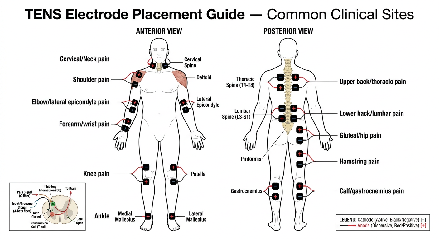
- Neck/cervical - bilateral paravertebral pads for cervicogenic pain
- Shoulder - deltoid region pads for rotator cuff/AC joint pain
- Lateral elbow - straddling the epicondyle for tennis elbow
- Forearm/wrist - dorsal surface for distal upper limb pain
- Knee - 4-electrode quadrant arrangement around the joint line
- Ankle - bilateral malleolar placement
- Upper back - paravertebral T4-T8 pairs for thoracic pain
- Lower back - 4-electrode grid over L3-S1 for lumbar pain (most common clinical use)
- Gluteal/hip - over piriformis for deep hip/sciatic pain
- Hamstring - posterior thigh for muscle pain
- Calf - gastrocnemius belly for plantar fasciitis/calf pain
| Rule | Explanation |
|---|---|
| Cathode (-) is active | Placed closer to the pain site; produces stronger tingling sensation |
| Anode (+) is dispersive | Placed proximally or at the nerve root level |
| Electrode spacing | Minimum 2-3 cm apart; never overlap |
| Avoid midline spine | Pads must be paravertebral (beside the spinous processes, not over them) |
| Straddling pain | For localised pain, place one pad on each side of the painful area |
| Proximal-distal | For nerve pain (radiculopathy), one pad at nerve root, one distally over dermatome |
1. Define Coupling media & Define piezoelectric effect? Make it for 5 marks to write it in exam
Q1. Define Coupling Media in Ultrasound Therapy (5 Marks)
Definition
Why It Is Needed
Properties of an Ideal Coupling Medium
| Property | Requirement |
|---|---|
| Acoustic impedance | Similar to that of skin and soft tissue |
| Consistency | Viscous enough to stay at the skin surface without running off |
| Chemical nature | Non-irritant, non-toxic, water-based |
| Air content | Must be air-free (de-aerated) |
| Sterility | Sterile preparations available for use over wounds |
Types of Coupling Media Used in Clinical Practice
- Standard ultrasound transmission gel
- Water-based, air-free, non-greasy
- High acoustic transmission efficiency
- Used for both diagnostic and therapeutic ultrasound
- Used when the transducer cannot be placed directly on an irregular or painful surface (e.g., hands, fingers, feet, ankles)
- Patient's limb and the transducer are both submerged in degassed water
- Water must be degassed (boiled and cooled) to remove air bubbles
- Used in some clinical settings as an alternative
- Adequate acoustic transmission but less commonly used
Clinical Note
Q2. Define the Piezoelectric Effect (5 Marks)
Definition
Two Components of the Piezoelectric Effect
A. Direct Piezoelectric Effect (Generator Effect)
- When a mechanical force (pressure/compression) is applied to a piezoelectric crystal, the crystal lattice deforms.
- This deformation causes a redistribution of electrical charges within the crystal, generating a measurable electric voltage across its faces.
- In diagnostic ultrasound: returning sound echoes strike the transducer crystal, mechanically deforming it, and generating electrical signals that are converted into images on the ultrasound screen.
B. Reverse (Converse) Piezoelectric Effect (Motor Effect)
- When an alternating electrical current is applied across a piezoelectric crystal, the crystal rapidly expands and contracts (vibrates).
- This vibration produces mechanical pressure waves - ultrasound waves - that radiate from the transducer into the tissue.
- In therapeutic ultrasound: the generator applies alternating current at 1 MHz or 3 MHz to the crystal, causing it to vibrate and emit ultrasound energy into the patient's tissues.
Materials That Exhibit the Piezoelectric Effect
| Material | Type | Use |
|---|---|---|
| Quartz | Natural crystal | Early ultrasound devices |
| Lead zirconate titanate (PZT) | Synthetic ceramic | Modern therapeutic & diagnostic transducers |
| Barium titanate | Synthetic ceramic | Some older transducers |
| Polyvinylidene fluoride (PVDF) | Polymer | High-frequency applications |
Summary Diagram (for exam drawing)
ELECTRIC CURRENT → [CRYSTAL] → MECHANICAL VIBRATION → ULTRASOUND WAVES
(Reverse Piezoelectric Effect — used in TRANSMISSION)

SOUND PRESSURE WAVES → [CRYSTAL] → ELECTRIC SIGNAL → IMAGE / MEASUREMENT
(Direct Piezoelectric Effect — used in RECEPTION)
Clinical Relevance
- Therapeutic ultrasound machines operate using the reverse piezoelectric effect to generate sound waves at 1 MHz (deep tissues, up to 5 cm) or 3 MHz (superficial tissues, up to 2 cm).
- The same crystal can both emit and receive ultrasound, making the transducer a bidirectional electromechanical converter.
- If the crystal is damaged or improperly coupled (air gap present), energy transmission is lost and treatment becomes ineffective.
- Coupling medium = fills air gap between transducer and skin to allow ultrasound transmission; aqueous gel is the standard; water bath for irregular surfaces
- Piezoelectric effect = crystal converts electricity → vibration (reverse effect, used to generate US) and vibration → electricity (direct effect, used to receive echoes)
2. Describe Type of Infra red Generation make it for 5 marks for bpth 1year paper
types of infrared radiation generation luminous non-luminous physiotherapy BPTH 1st year
https://www.physiotattva.com/blog/infrared-radiation-therapy…
Q. Describe the Types of Infrared Radiation Generation (5 Marks)
Introduction
Classification of IR Based on Wavelength
| Type | Wavelength | Former Name | Therapeutic Use |
|---|---|---|---|
| IR-A (Near IR) | 760 - 1400 nm | Short / Near IR | Used in therapy - deeper penetration |
| IR-B (Mid IR) | 1400 - 3000 nm | Mid IR | Limited therapeutic use |
| IR-C (Far IR) | 3000 nm - 1 mm | Long / Far IR | Not used in therapy |
Types of IR Generators Used in Physiotherapy
1. Luminous IR Generator (Near Infrared / Short Wave IR)
- Consists of one or more incandescent tungsten filament lamps enclosed in a glass bulb
- Tungsten is used for the filament because it tolerates repeated heating and cooling
- The filament coil is connected to an electrical circuit and mounted in a parabolic reflector to direct the beam
- When electric current passes through the tungsten filament, the filament is heated to a very high temperature (~2500°C)
- This produces heat, infrared radiation, visible light, and a small amount of UV rays
- The UV rays are absorbed by the glass bulb and are not emitted
- The lamp emits IR with wavelengths of 780 nm - 1500 nm, with peak intensity at ~1000 nm
- Emits visible red/orange light along with IR (hence "luminous")
- Also called radiant heat lamp
- Warms up immediately upon switching on
- Penetration depth: 5-10 mm (into dermis and subcutaneous tissue)
- Power output: ~150-1500 W
- More effective for chronic lesions and subacute conditions
- Shorter wavelengths penetrate deeper, producing greater heating effect
2. Non-Luminous IR Generator (Far Infrared / Long Wave IR)
- Consists of a coiled resistance wire (nichrome wire) looped around or embedded in a ceramic insulating material
- The ceramic element is mounted at the focal point of a parabolic reflector with a wire mesh guard on the front
- Available in power levels of 750-1000 W
- Electric current passes through the resistance wire, heating the ceramic element to a temperature of ~500°C
- The heated ceramic emits infrared radiation only - no visible light (hence "non-luminous")
- Produces IR with peak wavelength of ~4000 nm (4 µm)
- Emits no visible light - radiation is invisible to the eye
- Has thermal inertia - takes 5 to 15 minutes to reach peak emission due to the large mass of ceramic material that must be heated
- Penetration depth: up to 2 mm (superficial - epidermis only)
- Longer wavelength = more superficial effect
- More effective for acute inflammatory conditions
- Produces a sedative/analgesic effect due to longer wavelength, more superficial action
- Suitable when deep heating is not desired
Comparison Table: Luminous vs Non-Luminous Generator
| Feature | Luminous | Non-Luminous |
|---|---|---|
| Visible light | Yes (red/orange glow) | No |
| Wavelength | 780-1500 nm (peak 1000 nm) | ~4000 nm (4 µm) |
| IR type | Near IR (IR-A) | Far IR (IR-C) |
| Penetration | 5-10 mm (dermis + subcutaneous) | Up to 2 mm (epidermis) |
| Warm-up time | Immediate | 5-15 minutes |
| Temperature generated | ~2500°C (filament) | ~500°C (ceramic) |
| Best used for | Chronic / subacute conditions | Acute inflammatory conditions |
| Heating effect | Deeper, stronger | Superficial, sedative |
Treatment Distance & Dosage (Important for Exams)
- Generator placed 45-75 cm from the treatment area
- Duration: 10-20 minutes per session
- Test skin sensation before treatment
- Eyes must be protected (patient and therapist)
- Luminous = tungsten filament + visible light + near IR + deeper penetration (5-10 mm) + chronic conditions
- Non-luminous = ceramic resistance wire + no visible light + far IR + superficial (2 mm) + acute conditions + takes 5-15 min to warm up
- The shorter the wavelength → the greater the penetration depth
- Natural source of IR = the sun
4. Explain the method of testing US? For 5 marks to write in exam
methods of testing ultrasound machine physiotherapy ERA BNR output power BPTH exam
methods testing therapeutic ultrasound machine degassed water aluminium foil ball bearing test output verification
"testing of ultrasound" physiotherapy "water test" OR "foil test" OR "ERA" OR "BNR" methods clinical site
Q. Explain the Methods of Testing Ultrasound (US) Machine (5 Marks)
Introduction
- It is producing actual ultrasound output (not just heat in the head)
- The output is accurate and calibrated
- The transducer is functioning and the beam characteristics are within safe limits
A. Simple Clinical Tests
1. Water Test (Ripple Test / Degassed Water Test)
- Fill a shallow bowl with degassed water (boiled and cooled to remove dissolved air/gas bubbles)
- Switch on the US machine and set intensity to 1-2 W/cm²
- Immerse the transducer head just below the water surface (1-2 cm deep)
- Observe the water surface
- Ripples or waves appear on the water surface immediately
- Fine turbulence (streaming) is visible around the transducer face
- No movement or ripples visible = no ultrasound being produced
2. Aluminium Foil Test (Cavitation Test)
- Hold a small piece of thin aluminium foil (11-15 microns thick) in a container of degassed water
- Activate the US machine at high intensity (~2 W/cm²)
- Direct the transducer face toward the foil for 30-60 seconds
- Small holes (pits/perforations) appear in the foil surface
- Confirms that cavitation is occurring = ultrasound energy is genuine
3. Ball Bearing Test (Thermal Test)
- Apply coupling gel to the transducer head
- Place the transducer against a small steel ball bearing
- Switch on at moderate intensity for 30-60 seconds
- Feel the ball bearing
B. Technical / Quantitative Tests
4. ERA Measurement (Effective Radiating Area)
- ERA is always smaller than the physical size of the soundhead
- The intensity prescribed (W/cm²) is calculated as: Intensity = Power (W) ÷ ERA (cm²)
- If ERA is inaccurate, the actual tissue dose differs from the set dose
- Measured using a hydrophone scanning technique
5. BNR Measurement (Beam Nonuniformity Ratio)
| BNR Value | Interpretation |
|---|---|
| 2-4 | Excellent - uniform beam, low hot-spot risk |
| 4-6 | Acceptable - some non-uniformity |
| >6 | Poor - high hot-spot risk, tissue damage possible |
| ≥8 | Not acceptable for clinical use |
6. Output Power Verification (Wattmeter / Radiation Force Balance)
- A radiation force balance (also called acoustic power meter) measures the actual power output in Watts
- The transducer is directed into a water tank onto a radiation-absorbing target
- The force exerted on the target is converted to power output
- The measured value is compared to the set value on the machine dial
Summary Table
| Test | Principle | Equipment | What It Confirms |
|---|---|---|---|
| Water / Ripple Test | Mechanical agitation | Bowl of degassed water | US output present |
| Aluminium Foil Test | Acoustic cavitation | Thin Al foil + water | Cavitation = genuine US |
| Ball Bearing Test | Thermal absorption | Steel ball bearing | Heat production from US |
| ERA Measurement | Hydrophone scanning | Hydrophone + water tank | Actual radiating area |
| BNR Measurement | Beam mapping | Hydrophone | Beam uniformity / hot spots |
| Power Verification | Radiation force balance | Wattmeter | Accuracy of output intensity |
- The water (ripple) test is the simplest and most commonly used clinical test
- Degassed water is mandatory to avoid false positives from air bubbles
- ERA determines the true dose delivered; BNR determines safety of the beam
- A machine with BNR ≥ 8 should NOT be used clinically
- Machines should be calibrated regularly - output can drift by ±20% or more over time with use
5. Principle of US with panel digram? Make it for 5 marks in points and short
Detailed labeled panel diagram showing the principle of therapeutic ultrasound machine for physiotherapy. Show 4 connected panels in a clean medical education style on white background: PANEL 1 - "Electrical Generator": Show an electrical oscillator/generator box producing alternating current at 1 MHz or 3 MHz. Label: AC generator, frequency selector dial (1MHz/3MHz), output cable. PANEL 2 - "Piezoelectric Crystal (Transducer)": Cross-section of the soundhead showing: metal casing, piezoelectric crystal (PZT - lead zirconate titanate), crystal vibrating rapidly (show compression/expansion arrows), coaxial cable connection, faceplate. Label the reverse piezoelectric effect: "Electrical energy → Mechanical vibration". PANEL 3 - "Coupling Medium & Skin Interface": Show the transducer head pressed against skin with aqueous gel layer between them. Show the gel filling the air gap. Label: transducer faceplate, coupling gel layer, skin surface (epidermis), dermis, subcutaneous tissue. Show ultrasound beam entering tissue as cone-shaped wave lines. PANEL 4 - "Tissue Effects": Show a cross-section of soft tissue with ultrasound waves penetrating. Label: longitudinal compression waves, 1 MHz = deep penetration (3-5 cm), 3 MHz = superficial penetration (1-2 cm), thermal effects (heat symbol), non-thermal effects (cavitation micro-bubbles and acoustic streaming arrows). Connect all 4 panels with labeled arrows showing energy flow: Electrical Energy → Mechanical Vibration → Acoustic Waves → Tissue Effects. Add title at top: "PRINCIPLE OF THERAPEUTIC ULTRASOUND". Use blue and teal color scheme, clean lines, professional medical diagram style.
principle of therapeutic ultrasound machine physiotherapy production mechanism tissue effects 1MHz 3MHz
Q. Principle of Therapeutic Ultrasound with Panel Diagram (5 Marks)
Definition
Panel Diagram
╔══════════════╗     ╔══════════════╗     ╔══════════════╗     ╔══════════════╗
║   PANEL 1    ║────▶║   PANEL 2    ║────▶║   PANEL 3    ║────▶║   PANEL 4    ║
║  ELECTRICAL  ║     ║PIEZOELECTRIC ║     ║   COUPLING   ║     ║   TISSUE     ║
║  GENERATOR   ║     ║  TRANSDUCER  ║     ║   MEDIUM     ║     ║   EFFECTS    ║
╠══════════════╣     ╠══════════════╣     ╠══════════════╣     ╠══════════════╣
║              ║     ║  [Crystal]   ║     ║  Transducer  ║     ║ ≋≋≋≋≋≋≋≋≋≋  ║
║  AC Current  ║     ║  ~~~↕~~~     ║     ║ ─────────── ║     ║  THERMAL    ║
║  1 or 3 MHz  ║     ║  vibrates    ║     ║    GEL       ║     ║  (heat)     ║
║  oscillator  ║     ║  rapidly     ║     ║ ─────────── ║     ║             ║
║              ║     ║              ║     ║   SKIN       ║     ║ ∿∿∿∿∿∿∿∿∿∿  ║
║  ⚡→→→→→→→   ║     ║ Electrical   ║     ║ ─────────── ║     ║  NON-THERMAL║
║              ║     ║ energy →     ║     ║  Tissue      ║     ║ (cavitation)║
║              ║     ║ Mechanical   ║     ║              ║     ║             ║
║              ║     ║ vibration    ║     ║  No air gap  ║     ║             ║
╚══════════════╝     ╚══════════════╝     ╚══════════════╝     ╚══════════════╝
  Electrical            Reverse             Transmission          Biological
  Energy                Piezoelectric       of waves              Response
                        Effect
Principle - Step by Step (Points)
- The US machine contains a high-frequency electrical oscillator
- Generates alternating current (AC) at exactly 1 MHz (for deep tissues, 3-5 cm) or 3 MHz (for superficial tissues, 1-2 cm)
- Frequency is selected by the clinician on the control panel
- AC current passes through a piezoelectric crystal (lead zirconate titanate - PZT) inside the transducer head
- The crystal rapidly expands and contracts (vibrates) at the same frequency as the applied current
- This converts electrical energy → mechanical vibration → ultrasonic pressure waves
- This is called the Reverse Piezoelectric Effect
- Ultrasound cannot travel through air (total reflection occurs at air-skin interface)
- Aqueous coupling gel is applied between transducer and skin to eliminate the air gap
- This ensures efficient transmission of ultrasonic waves into tissue
- For irregular surfaces, water bath immersion is used as the coupling medium
- US travels as longitudinal compression waves through soft tissue
- Tissue molecules are alternately compressed and rarefied as the wave passes
- Protein-rich tissues (muscle, tendon, bone) absorb more energy than water-rich tissues (fat)
- The transducer is kept in continuous circular motion at 1-2 cm/sec to avoid standing waves and hot spots
| Mode | Effect | Mechanism |
|---|---|---|
| Continuous US | Thermal - raises tissue temperature by 1-4°C | Friction from molecular vibration → heat |
| Pulsed US | Non-thermal - no significant heating | Acoustic cavitation + acoustic streaming |
- Thermal effects: Increased blood flow, reduced muscle spasm, increased collagen extensibility, accelerated metabolism
- Acoustic cavitation: Formation and oscillation of micro-gas bubbles in tissue fluid → changes cell membrane permeability → promotes healing
- Acoustic streaming: Unidirectional movement of fluid along cell membranes → enhanced ion transport and tissue repair
Key Numbers to Remember
| Parameter | Value |
|---|---|
| Frequency range | 0.5 - 3 MHz |
| 1 MHz penetration | 3-5 cm (deep) |
| 3 MHz penetration | 1-2 cm (superficial) |
| Intensity range | 0.1 - 3.0 W/cm² |
| Treatment duration | 5-10 min per session |
| Transducer speed | 1-2 cm/second |
| US wavelength in tissue | ~1.5 mm at 1 MHz |
"Therapeutic ultrasound works by converting electrical energy into mechanical sound waves via the reverse piezoelectric effect in a crystal transducer, transmitted through coupling gel into tissues where it produces thermal (continuous mode) and non-thermal (pulsed mode) biological effects to promote healing and pain relief."