
Mechano therapy after extraction of first premolars in ortho
mechano therapy after first premolar extraction orthodontics space closure sequence
orthodontic space closure after premolar extraction mechanics
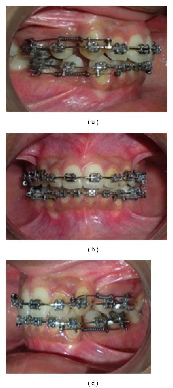
This composite of three intraoral clinical photographs (labeled a, b, and c) illustrates the progression of extraction space closure in a patient undergoing orthodontic treatment. The images show both maxillary and mandibular arches fitted with fixed orthodontic appliances, including metal brackets, a continuous stainless steel archwire, and specialized open-coil retraction springs (OCRS). The OCRS is positioned along the archwire, spanning the extraction gaps. In the initial stage (a), the extraction spaces are wide, and the OCRS is stretched and activated. As treatment progresses through (b) and (c), the extraction spaces visibly narrow as the anterior teeth are retracted and the posterior teeth mesially migrate. The OCRS decompresses accordingly; the spring coils appear less stretched and the overall distance between the engaging hooks (attached to the archwire anteriorly and molar hooks posteriorly) decreases. These images demonstrate the clinical application of sliding mechanics for 'en-masse' retraction of anterior teeth following premolar extractions.

Clinical intraoral photographs showing the orthodontic management of a maxillary arch for space closure following the extraction of tooth #14 (upper right first premolar). The composite image displays lateral and frontal views of fixed orthodontic appliances. A rectangular stainless steel archwire is seated in standard orthodontic brackets across both the maxillary and mandibular arches. The primary educational focus is the 'sliding mechanics' setup on the patient's right side (left side of the image). This includes a hook placed on the archwire distal to tooth #12 (lateral incisor) and a superelastic nickel-titanium (NiTi) closed-coil spring extending from the hook to the molar region (tooth #16). This configuration provides a continuous force (approximately 300g) to close the extraction space by retracting the anterior segment. The clinical scenario demonstrates the alignment, leveling, and space closure phases of treating an Angle Class II, Division 1 malocclusion with tooth-bone discrepancy.
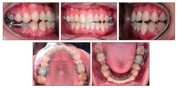
A composite of five intraoral clinical photographs documenting orthodontic treatment for space closure in a 24-year-old male. The images include frontal, lateral (right and left), and occlusal views (maxillary and mandibular) of the dental arches. The mandibular arch demonstrates active space closure using a combination of labial and lingual mechanics. Key components include metallic molar bands, brackets, and a stainless steel archwire. Power chains (elastic chains) are visible extending from the mandibular right second molar to the mandibular left third molar on both the labial and lingual surfaces to manage space and prevent unwanted rotation or bowing. Clear composite buttons are bonded to the labial surfaces of the mandibular canines to facilitate elastic attachment. A segmental archwire is utilized in the lower right quadrant between the second premolar and second molar. The frontal view shows a slight anterior open bite and midline discrepancy. The occlusal views reveal the lingual appliance setup and the extraction sites undergoing closure. Gingival health appears stable with no significant inflammation visible.
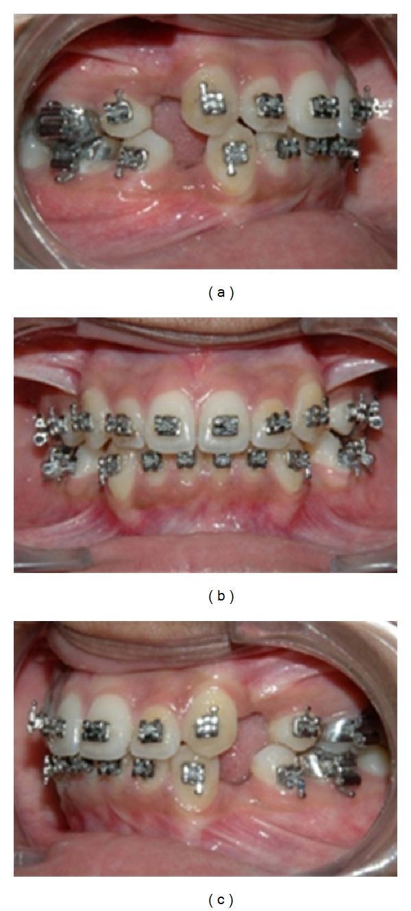
This composite of three intraoral clinical photographs demonstrates the 'alignment and leveling' phase of orthodontic treatment in a patient with bimaxillary protrusion. (a) Right lateral view showing 0.018 pre-adjusted edentulous (PEA) brackets and a continuous archwire. A significant extraction space is visible where the first premolar was removed. (b) Frontal view showing the maxillary and mandibular arches with brackets bonded to the labial surfaces. The teeth exhibit improved but incomplete alignment, with some persisting rotations. (c) Left lateral view showing a corresponding extraction space in the first premolar region. Standard metal brackets are present on the anterior teeth and premolars, while molar tubes are visible on the posterior teeth to provide anchorage. The images illustrate the clinical state after initial leveling, prior to the initiation of 'en-masse' retraction and space closure using sliding mechanics. The gingival tissue appears healthy, and the archwires are engaged with ligatures to facilitate tooth movement along the dental arch.
Mechano-Therapy After First Premolar Extraction in Orthodontics
Phase 1 - Alignment and Leveling
- Bond brackets immediately or within 1-2 weeks of extraction
- Sequence wires: 0.014" NiTi → 0.016" NiTi → 0.016×0.022" NiTi → 0.017×0.025" NiTi → 0.019×0.025" SS
- The teeth adjacent to the extraction site (canine distally, second premolar mesially) begin drifting spontaneously during this phase - this is normal and acceptable
- Avoid closing spaces prematurely before adequate leveling; doing so causes "rollercoaster effect" (extrusion of anteriors and posteriors)
Phase 2 - Space Closure
A. Sliding Mechanics (Friction Mechanics)
- Rectangular stainless steel wire (minimum 0.019×0.025" in 0.022" slot, or 0.017×0.025" in 0.018" slot)
- Low-friction brackets preferred (self-ligating or passive ligation)
| Appliance | Force Magnitude | Notes |
|---|---|---|
| NiTi closed coil spring | 150-200 g | Most common; continuous force |
| Power chain (elastic chain) | ~100-150 g (decays rapidly) | Less ideal - force degrades |
| Elastic modules | Variable | Used in mild cases |
-
Two-step (canine retraction first, then en-masse anterior retraction):
- Step 1: Retract canine alone into extraction space using a canine hook + NiTi coil spring to molar
- Step 2: Once canine is in Class I, retract 4 anterior teeth en-masse
- Advantage: better torque control, classic Tweed-Merrifield approach
-
En-masse retraction (all 6 anteriors together):
- Hook on archwire distal to lateral incisor (or power arm on bracket)
- NiTi closed coil spring from hook to molar tube
- Common in bimaxillary protrusion cases
- Requires good anchorage (often with TADs)
B. Frictionless Mechanics (Loop Mechanics)
| Loop | Characteristics |
|---|---|
| Vertical closing loop | Simple, delivers tipping force; needs gable bends for torque |
| T-loop (Burstone) | Most popular; adjustable M/F ratio; can achieve controlled tipping to bodily movement |
| Opus loop | High M/F ratio; bodily movement |
| Mushroom loop | Modified for specific tooth movements |
- Placed in 0.016×0.022" or 0.017×0.025" TMA (beta-titanium) wire
- Activated 1-2 mm at each visit
- Positioning the T-loop mesial or distal to the center determines whether anterior or posterior segment moves more (anchorage control)
- M/F ratio of 8-12:1 for bodily movement; <7:1 causes tipping
Phase 3 - Anchorage Control
| Anchorage Type | Space Distribution | Clinical Indication |
|---|---|---|
| Maximum anchorage | >75% anterior retraction | Severe bimaxillary protrusion, full Class II correction |
| Moderate anchorage | ~50/50 split | Moderate protrusion, half-cusp Class II |
| Minimum anchorage | <25% anterior movement | Crowding relief only, good profile |
- Nance palatal arch / transpalatal arch (TPA): Passive anchorage; prevents molar rotation and mesialization
- Headgear (cervical/occipital): Active extra-oral anchorage; also moves molars distally
- Temporary Anchorage Devices (TADs / mini-screws): Gold standard for maximum anchorage; placed in infrazygomatic crest, palate, or interdental bone
- Class II / Class III elastics: Used when differential upper-lower retraction is needed
Phase 4 - Torque Control and Root Paralleling
- Torque in the archwire: Prescription torque (e.g., Roth, MBT) or additional third-order bends
- Power arms / extended hooks: Shift force application apically to reduce tipping moment
- Gable bends: Placed in closing loops (T-loops, vertical loops) - anterior gable produces lingual root torque; posterior gable tips molar crowns distally (prevents anchorage loss)
- Tip-back bends: Added to molar region to resist mesial tipping during retraction
Phase 5 - Finishing and Detailing
- Wire progression: Step back to lighter rectangular wires for fine detailing
- Settling elastics: Vertical or box elastics to improve intercuspation
- Root paralleling: Confirmed by periapical radiographs; small tip adjustments made in archwire
- Midline correction: Asymmetric elastics or differential activation
- Occlusal plane control: Reverse curve of Spee (lower arch) or accentuated curve of Spee (upper arch) as needed
Class-Specific Considerations
| Malocclusion | Mechano-Therapy Strategy |
|---|---|
| Class I with bimaxillary protrusion | All 4 first premolars extracted; maximum anchorage; en-masse retraction with TADs |
| Class II Div 1 | Upper 4s extracted; upper retraction with Class II elastics; lower arch non-extraction or asymmetric |
| Class II Div 2 | Upper 4s extracted; labial root torque of upper incisors required before/during retraction |
| Class III | Lower 4s extracted (sometimes); lower retraction with Class III elastics; camouflage treatment |
| Asymmetric cases | Unilateral extraction + asymmetric mechanics (e.g., box elastics, unilateral TAD) |
Key Biomechanical Principles to Remember
- M/F ratio determines tooth movement type: Low (<5:1) = uncontrolled tipping; 7:1 = controlled tipping; 10:1 = bodily movement; >12:1 = torque
- Force level for space closure: 150-200 g per side is optimal; excessive force causes hyalinization and anchorage loss
- Friction in sliding mechanics is a major limitation - bracket-wire interface generates 50-300 g of friction depending on wire, bracket, and ligation
- TADs (mini-screws) have shifted modern orthodontics toward greater anchorage control and en-masse retraction protocols
- Regional acceleratory phenomenon (RAP): Early space closure (within 1 week of extraction) can exploit the post-extraction inflammatory response for faster tooth movement
Common Wire Sequence Summary
Alignment:    0.012 NiTi → 0.014 NiTi → 0.016 NiTi → 0.016×0.022 NiTi → 0.017×0.025 NiTi
Space closure: 0.017×0.025 SS or 0.019×0.025 SS (sliding) / 0.017×0.025 TMA (loops)
Finishing:    0.016×0.022 SS → 0.014 NiTi for settling