
Linear accelerator components (10marks answers)
Reading File
Now let me search the medical library for linear accelerator components.
Finding Sources
Searching the Web
linear accelerator components medical physics radiotherapy detailed
Finding Sources
Reading File
There's a block diagram in the textbook. Let me read that section and fetch the image simultaneously.
Reading File
Finding Sources
Loading Image
Reading File
I now have the block diagram image and substantial textbook content. Let me compile a comprehensive 10-mark answer.
Linear Accelerator (LINAC) - Components
Source: Cummings Otolaryngology Head & Neck Surgery
Block Diagram
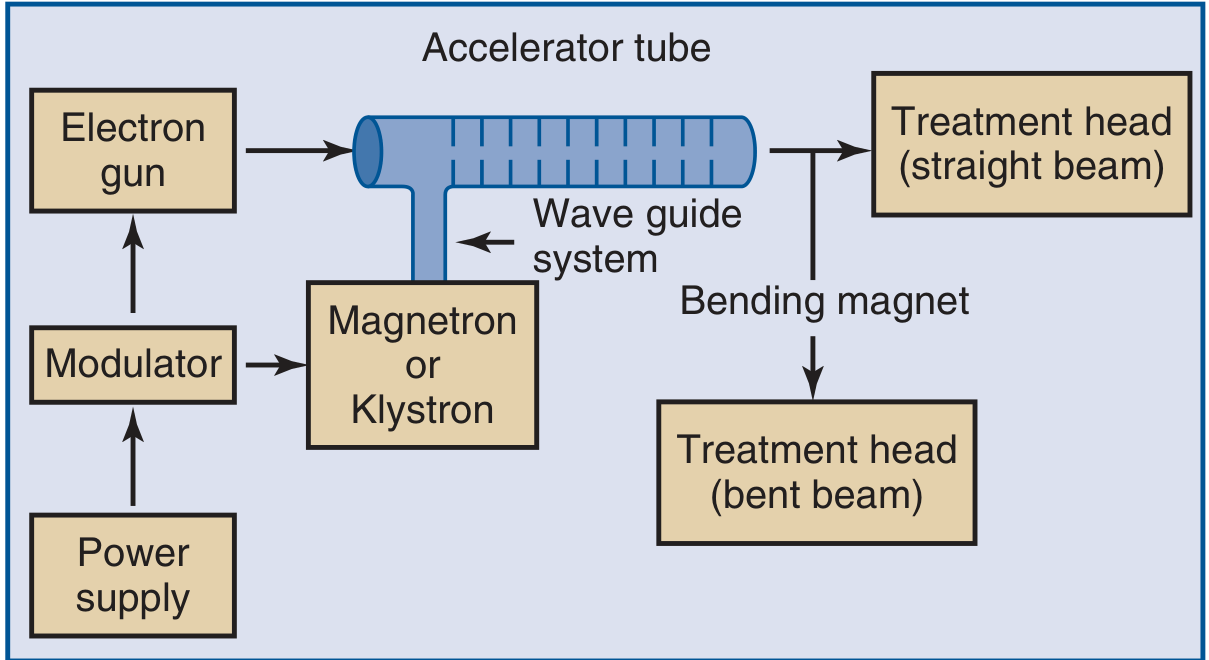
Fig. 75.3 - Block diagram of a typical medical linear accelerator (Leibel SA, Phillips TL, Textbook of Radiation Oncology)
Introduction
A linear accelerator (LINAC) is a device that uses high-frequency electromagnetic waves to accelerate electrons to high energies through a linear tube. It is the most widely used machine in modern radiotherapy. Commercially available medical LINACs produce x-rays and electrons with energies ranging from 4 MeV to ~25 MeV.
Major Components
1. Power Supply
- Provides the primary electrical power to the entire system.
- Feeds into the modulator to generate high-voltage pulses.
2. Modulator
- Converts the continuous power supply into short, high-voltage pulses.
- These pulses are delivered simultaneously to both the electron gun and the microwave power source (magnetron or klystron).
- Ensures timing synchronization between the electron injection and the microwave acceleration cycle.
3. Electron Gun
- Produces the initial beam of electrons through thermionic emission (a heated cathode emits electrons).
- These electrons are injected into the accelerator (waveguide) tube in synchronized pulses.
- The electron gun is triggered by the modulator to inject electrons at the exact right moment so that they encounter maximum accelerating voltage in the waveguide.
4. Microwave Power Source: Magnetron or Klystron
- These are the "engines" of the LINAC - they generate the high-power microwave radiofrequency (RF) energy that accelerates the electrons.
- Magnetron: A self-contained microwave oscillator; generates its own microwave power. Used in low- to medium-energy LINACs (up to ~6 MeV).
- Klystron: A microwave amplifier, not a generator. It amplifies a low-power input signal to a high-power output. Used in high-energy LINACs (above 6 MeV). More stable and longer-lasting than the magnetron.
- Both feed microwave energy into the waveguide system.
5. Waveguide (Accelerator Tube) System
- The core of the LINAC - a copper tube divided into a series of cavities by discs (irises) with central holes.
- Two main types:
- Travelling wave guide: Microwaves travel in one direction along the tube.
- Standing wave guide: Microwaves create a standing wave pattern inside the tube.
- As the electron bundle passes through the tube, the spacing of the gaps between electrodes is designed so that the maximum voltage appears exactly as each particle crosses the gap - this accelerates the particle and imparts energy in the form of increased velocity.
- At speeds near the speed of light, additional energy appears as an increase in the relativistic mass of the particles.
- Additional magnetic/electrostatic focusing lenses ensure the beam stays centered within the tube.
6. Bending Magnet
- Once electrons are accelerated to the desired energy, they exit the waveguide.
- In low-energy machines (up to ~6 MeV), the accelerating tube is short and can be oriented directly toward the patient - this gives a straight beam design.
- In higher-energy machines, the tube is too long to point directly at the patient, so a bending magnet deflects the electron beam through 90° or 270° toward the treatment head.
- Acts as an energy filter, ensuring only electrons of the correct energy are directed at the target.
7. Treatment Head (Gantry Head)
This is the final component from which radiation exits toward the patient. It contains multiple sub-components:
| Sub-component | Function |
|---|---|
| Tungsten target | Electrons strike this and produce x-rays via bremsstrahlung radiation |
| Primary collimator | Fixed collimator that limits the maximum beam size |
| Flattening filter | Modifies the forward-peaked x-ray beam to produce a uniform dose profile |
| Ion chamber | Monitors beam output (dose), flatness, and symmetry in real time |
| Secondary collimators (jaws) | Movable tungsten jaws that define the rectangular field size |
| Multileaf collimator (MLC) | Set of many thin tungsten leaves that shape the beam to the tumor contour; enables IMRT |
| Wedges/compensators | Modify dose distribution to account for patient body contour |
| Light field/range finder | Optical system that projects the radiation field onto the patient's skin for positioning |
- In electron mode, the tungsten target and flattening filter are moved out of the beam path, and scattering foils are placed in instead to spread the electron beam evenly.
8. Gantry and Isocenter
- The gantry is the rotating arm that holds the treatment head and can rotate 360° around the patient.
- The isocenter is the fixed point in space (typically 100 cm from the x-ray source) around which the gantry, collimator, and treatment couch all rotate.
- All beams converge at the isocenter, which is placed within the tumor during treatment.
9. Treatment Couch
- A precisely calibrated, computer-controlled table that moves in 6 directions (x, y, z, pitch, roll, yaw) to position the patient accurately.
10. Control Console & Monitoring System
- Allows the therapist to control beam energy, dose rate, field size, and gantry angle from outside the treatment room.
- The ionization chamber in the treatment head continuously monitors beam output and shuts the machine off once the prescribed dose (monitor units, MU) is delivered.
Summary Table
| Component | Role |
|---|---|
| Power Supply | Primary electrical source |
| Modulator | Creates synchronized high-voltage pulses |
| Electron Gun | Produces and injects electron beam |
| Magnetron / Klystron | Generates / amplifies microwave energy |
| Waveguide (Accelerator Tube) | Accelerates electrons to megavoltage energies |
| Bending Magnet | Redirects high-energy electron beam to treatment head |
| Tungsten Target | Converts electrons to x-rays (bremsstrahlung) |
| Flattening Filter | Produces uniform beam profile |
| Collimators / MLC | Shapes and sizes the treatment field |
| Isocenter / Gantry | Ensures all beams converge at tumor |
Key Points for Exam:
- LINACs produce x-rays (4-25 MV) via bremsstrahlung when electrons hit a tungsten target, or can produce electron beams directly.
- The magnetron generates microwaves; the klystron amplifies them - both serve as the RF source.
- The waveguide is the accelerating structure; gap spacing is designed so maximum voltage coincides with the electron's transit through each gap.
- The bending magnet is only needed in high-energy machines where the tube is too long for a straight-beam design.
- The MLC is the key component enabling modern techniques like IMRT and VMAT.
This is a shared conversation. Sign in to Orris to start your own chat.