
Counter current mechanism and glomerulus - KIDNEY IN MD ANAESTHESIA RELAVENT
counter current mechanism kidney loop of Henle diagram
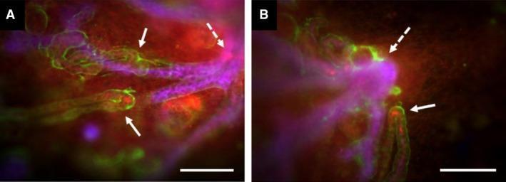
This dual-panel fluorescence microscopy image (A and B) demonstrates the developmental orientation of the loop of Henle in cultured embryonic mouse kidney cortex (E11.5 + 7d). The visual captures two primary tubular systems: the branching collecting duct system, stained purple-blue (CalbindinD28k), and the developing loops of Henle, delineated by green and red signals. The green fluorescence (anti-laminin) marks the basement membranes of the tubules, while the red signal identifies Tamm-Horsfall Protein (THP), a marker for maturing loops of Henle. Solid white arrows highlight the hairpin-like terminal ends or 'tips' of these loops, where red THP expression is most intense. Dotted white arrows point to the primary branch points of the collecting duct network. The images illustrate a clear centripetal growth pattern, where the loops of Henle extend and orient themselves toward the oldest, largest junctions of the collecting duct system. This configuration serves as an educational model for renal morphogenesis and the spatial navigation of nephron segments during kidney development. Scale bars: 200 μm.
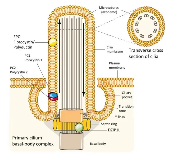
This digital schematic illustration depicts the molecular pathophysiology of autosomal recessive polycystic kidney disease (ARPKD). The image emphasizes a renal tubular epithelial cell with its primary cilium emanating from the apical membrane of a collecting duct/loop of Henle segment. The left side labels the PKHD1-encoded fibrocystin (fibrocystin/polyductin) protein localized to the ciliary membrane and apical plasma membrane, illustrating its role in the ciliopathy pathway alongside polycystin-1 (PC1) and polycystin-2 (PC2). The diagram highlights the basal body–transition zone complex, with DZIP1L positioned at centrioles and the distal basal body, underscoring its necessity for trafficking gene products into the ciliary axoneme. A transverse section inset shows microtubule axonemes and the ciliary pocket, connecting to the primary cilium’s sensory function. Arrows denote intracellular trafficking and-lumen orientation. Dysfunctions in fibrocystin and DZIP1L disrupt ciliary signaling, promoting cystogenesis in ARPKD and reflecting a ciliopathy mechanism shared with other cystic diseases. The illustration also notes that fibrocystin is variably expressed in pancreatic and bile duct epithelium, consistent with multisystem involvement. This visualization serves educational purposes for genetics, nephrology, and cell biology, and supports research into targeted therapies addressing ciliary assembly and trafficking defects. Clinicians and students can correlate genotype–phenotype concepts with this concise framework for learning.
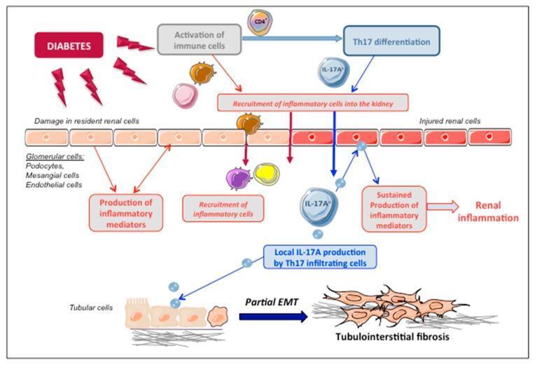
This pathophysiology diagram illustrates the mechanism of IL-17A-mediated renal injury in diabetic nephropathy. The flowchart originates with 'Diabetes' leading to two concurrent pathways: the activation of immune cells and damage to resident renal cells (podocytes, mesangial cells, and endothelial cells). The immune pathway details the differentiation of CD4+ T-lymphocytes into Th17 cells, which infiltrate the kidney and produce local IL-17A. This cytokine acts back on injured renal cells, triggering a feedback loop that leads to the sustained production of inflammatory mediators and chronic renal inflammation. At the cellular level, the diagram highlights the effect of local IL-17A on tubular epithelial cells, depicting a morphological transition labeled as 'Partial EMT' (Epithelial-to-Mesenchymal Transition). Here, structured cuboidal tubular cells transform into elongated, spindle-shaped mesenchymal cells associated with extracellular matrix deposition, ultimately culminating in tubulointerstitial fibrosis. The visual summarizes the interplay between metabolic stress, Th17-driven inflammation, and structural remodeling in the progression of diabetic kidney disease.
Kidney - Counter-Current Mechanism & Glomerulus (MD Anaesthesia)
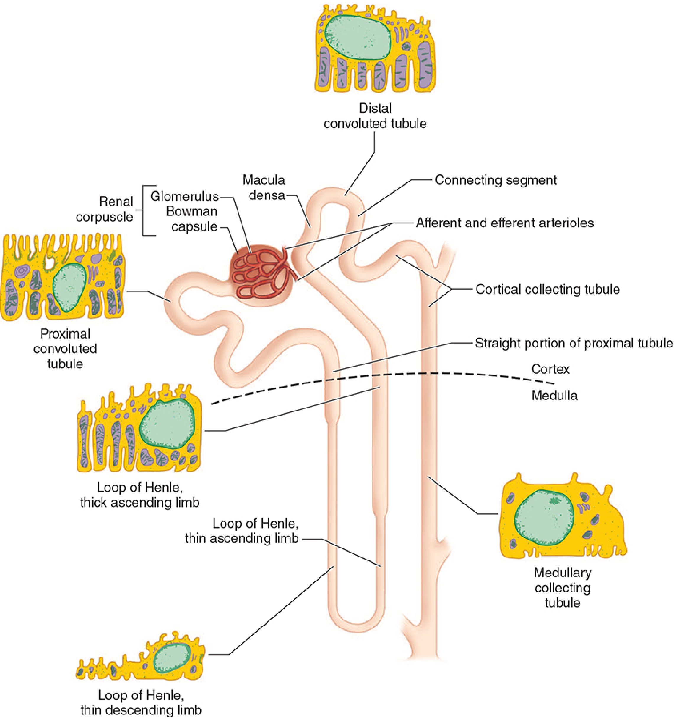
The Nephron - Overview
- Renal corpuscle (glomerulus + Bowman's capsule)
- Proximal convoluted tubule
- Loop of Henle
- Distal tubule
- Collecting tubule
- Juxtaglomerular apparatus
THE GLOMERULUS (Renal Corpuscle)
Structure
- Blood enters via single afferent arteriole and exits via single efferent arteriole
- The glomerular capillary tuft provides a large surface area for filtration
Three-Layer Filtration Barrier
| Layer | Detail |
|---|---|
| Endothelial cells | Fenestrated (70-100 nm pores); large - allow water, solutes, small proteins |
| Basement membrane (GBM) | Fused with epithelial basement membrane; negatively charged (favours cation filtration, repels albumin) |
| Epithelial cells (podocytes) | Interdigitate tightly - filtration slits ~25 nm; final barrier to large molecules |
Mesangial Cells (Third Cell Type)
| Cause Contraction (Decrease GFR) | Cause Relaxation (Increase GFR) |
|---|---|
| Angiotensin II | ANP (atrial natriuretic peptide) |
| Vasopressin (ADH) | Prostaglandin E2 |
| Norepinephrine | Dopaminergic agonists |
| Histamine, Endothelins | |
| Thromboxane A2 | |
| Leukotrienes C4, D4 |
Anaesthesia relevance: Dopamine and fenoldopam (D1 agonists) dilate afferent AND efferent arterioles, increasing GFR - this is the basis for their renoprotective use.
Glomerular Filtration Pressure (Starling Forces)
| Pressure | Value |
|---|---|
| Glomerular hydrostatic pressure | ~60 mmHg (driving force) |
| Plasma oncotic pressure | ~25 mmHg (opposing) |
| Renal interstitial pressure | ~10 mmHg (opposing) |
| Net filtration pressure | ~25 mmHg |
- GFP is ~60% of mean arterial pressure
- ~20% of plasma is filtered in each pass through the glomerulus (filtration fraction)
- Afferent tone - inversely proportional to filtration pressure
- Efferent tone - directly proportional to filtration pressure
GFR - Numbers to Know
| Measurement | Normal Value |
|---|---|
| GFR (men) | 120 ± 25 mL/min |
| GFR (women) | 95 ± 20 mL/min |
| Renal plasma flow (RPF) | ~660 mL/min |
| Renal blood flow (RBF) | ~1200 mL/min (20-25% of cardiac output) |
| Filtration fraction (FF = GFR/RPF) | ~20% |
TUBULAR OVERVIEW (before Counter-Current)
| Segment | % of Filtered Na+ Reabsorbed | Key Feature |
|---|---|---|
| Proximal tubule | 65-75% | Isotonic reabsorption, Na-K-ATPase driven |
| Loop of Henle | 15-20% | Counter-current multiplier |
| Distal tubule | ~5% | Aldosterone, Ca2+/Mg2+ regulation |
| Collecting tubule | 5-7% | ADH action, final urine concentration |
THE COUNTER-CURRENT MECHANISM
Components of the System
- Counter-current multiplier - Loop of Henle
- Counter-current exchanger - Vasa recta (paired capillaries)
The Loop of Henle - Structural Basis
| Segment | Permeability | Function |
|---|---|---|
| Thin descending limb | Permeable to water, Na+, Cl-, urea | Water drawn out by hypertonic medullary interstitium → tubular fluid becomes progressively more concentrated as it descends |
| Thin ascending limb | Permeable to Na+, Cl-, urea; but NOT water | Passive Na+ leak into interstitium |
| Thick ascending limb | Impermeable to water and urea | Active Na+/K+/2Cl- reabsorption (NKCC2 cotransporter) |
The Counter-Current Multiplier - Step by Step
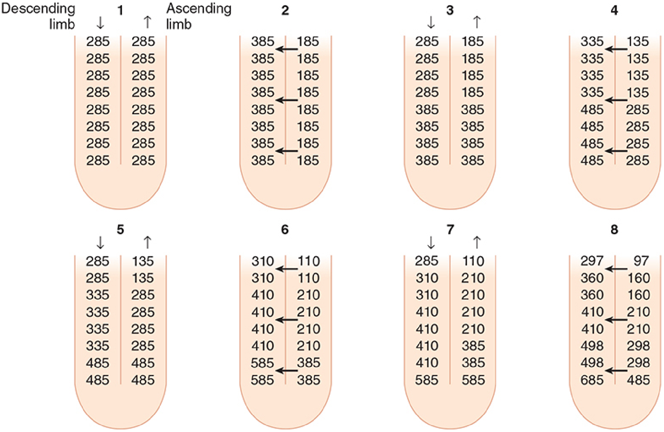
- At "time zero" (panel 1): all segments at 285 mOsm (isotonic)
- The thick ascending limb generates a 200 mOsm gradient at any single level (its maximum pumping capacity)
- As fluid flows, this single effect is multiplied by the counter-current flow arrangement
- End result: the papilla reaches 1200 mOsm (vs. cortex at 285 mOsm)
- Thick ascending limb pumps NaCl out → medullary interstitium becomes hypertonic
- Descending limb (permeable to water) - water moves out by osmosis → tubular fluid becomes concentrated (descending)
- Concentrated fluid turns at the tip and enters the ascending limb
- Ascending limb again pumps NaCl - further increasing medullary gradient
- This is repeated continuously → progressive amplification (multiplication) of the gradient from cortex to papilla
The fluid leaving the loop of Henle (entering the distal tubule) is hypotonic (100-200 mOsm/L) - because the thick ascending limb removed solute without water.
Urea's Contribution
The Counter-Current Exchanger - Vasa Recta
- Without vasa recta: blood flowing straight through the medulla would wash away the osmotic gradient
- With counter-current exchange: solutes diffuse into descending vasa recta and back out of ascending vasa recta - the gradient is preserved, not washed out
- Low blood flow to the medulla is also essential for maintaining the gradient (high flow would dilute it)
- The medulla consequently has a PO₂ of only ~15 mmHg - making it very vulnerable to ischaemia
ADH (Vasopressin) - The Master Switch
- Water to flow down the osmotic gradient created by the counter-current multiplier
- Tubular fluid equilibrates with the increasingly hypertonic medullary interstitium
- Final urine concentration up to 1200 mOsm/L (maximally concentrated)
RENAL AUTOREGULATION & ANAESTHESIA IMPLICATIONS
Autoregulation
- Maintained between MAP 80-180 mmHg via myogenic response of afferent arterioles
- Tubuloglomerular feedback: macula densa senses NaCl delivery; ↑ NaCl → afferent constriction → ↓ GFR (negative feedback)
- Prostaglandins (PGE2, PGD2, PGI2) are vasodilatory and protective - especially important during hypotension/ischaemia (NSAIDs abolish this protection)
Effects of Anaesthesia on Renal Function
| Effect | Mechanism |
|---|---|
| ↓ RBF, GFR, urine output | Both neuraxial and general anaesthesia (reversible if BP and volume maintained) |
| Fluid retention postoperatively | Endocrine response to surgery (↑ADH, ↑aldosterone, ↑renin-angiotensin) |
| Oliguria during laparoscopy | Pneumoperitoneum → ↑ IAP → renal vein/IVC compression + ↓CO + ↑renin/aldosterone/ADH |
| Sevoflurane (Compound A) | Nephrotoxic in animals at low fresh gas flow; use ≥2 L/min fresh gas flow as precaution |
| NSAIDs perioperatively | Block prostaglandin vasodilation → ↓ RBF under stress → AKI risk |
Key Vasomotor Effects on the Kidney
| Drug/Condition | Effect on Kidney |
|---|---|
| Dopamine, Fenoldopam | D1 receptor → dilate afferent + efferent arterioles; ↑ GFR and natriuresis |
| Angiotensin II | Constricts efferent > afferent; maintains GFR initially, but ↓ RBF |
| ACE inhibitors | Block Ang II → dilate efferent → ↓ GFR (hazardous in renal artery stenosis) |
| Norepinephrine | Afferent + efferent constriction → ↓ GFR |
| ANP | Dilates afferent, constricts efferent → ↑ GFR; also inhibits aldosterone |
QUICK SUMMARY FOR EXAM
- Three-layer filtration barrier (endothelium + GBM + podocytes)
- Net negative charge → repels albumin
- Filtration pressure = 60 mmHg; GFR ~120 mL/min
- Mesangial cells regulate GFR; contract with AngII, dilate with ANP
- Thick ascending limb: active NaCl reabsorption, impermeable to water → builds medullary gradient
- Descending limb: permeable to water → concentrates tubular fluid passively
- End result: medullary papilla ~1200 mOsm; fluid leaving loop ~100-200 mOsm (hypotonic)
- Hairpin capillaries trap solutes in medulla
- Low medullary blood flow preserves gradient
- PO₂ ~15 mmHg in medulla → ischaemia-prone
- All anaesthetics transiently ↓ RBF/GFR - maintain BP and volume
- NSAIDs are dangerous in hypovolaemic/hypotensive states
- Dopamine/fenoldopam are D1 renal vasodilators
- Laparoscopic pneumoperitoneum reliably causes oliguria (multifactorial)
- Sevoflurane: use ≥2 L/min fresh gas flow
Liver lobes- Anatomy, physiology, histological with portal circulation in md Anaesthesia
Liver: Anatomy, Physiology, Histology & Portal Circulation - MD Anaesthesia
PART 1: GROSS ANATOMY
Weight & Position
- Largest organ in the body: ~1500 g in adults
- Located in the right upper quadrant, fixed by hepatic veins and peritoneal ligaments
- Covered by Glisson's capsule (fibrous connective tissue) under the visceral peritoneum
Ligaments (Peritoneal Reflections)
| Ligament | Significance |
|---|---|
| Falciform ligament | Remnant of umbilical vein; runs from umbilicus to liver; divides left lobe; cephalad leaves cover suprahepatic IVC |
| Left triangular ligament | Fixes left lobe to diaphragm; divide to mobilise left lobe, exposing left IVC wall |
| Right triangular ligament | Fixes right lobe to right hemidiaphragm; divide to rotate liver left |
| Lesser omentum | Between stomach and liver; free right edge = hepatoduodenal ligament (portal triad) |
Anatomical Lobes (Morphological)
- Right lobe (larger) - with two additional smaller lobes on its posterior-inferior surface:
- Caudate lobe (segment I) - lies between IVC and ligamentum venosum; has its own direct hepatic vein drainage to IVC
- Quadrate lobe (part of segment IV) - lies between gallbladder fossa and falciform ligament
- Left lobe (smaller)
Surgical (Functional) Anatomy - Couinaud's Segments
- Inflow: portal vein branch + hepatic artery branch
- Outflow: hepatic vein branch + bile duct
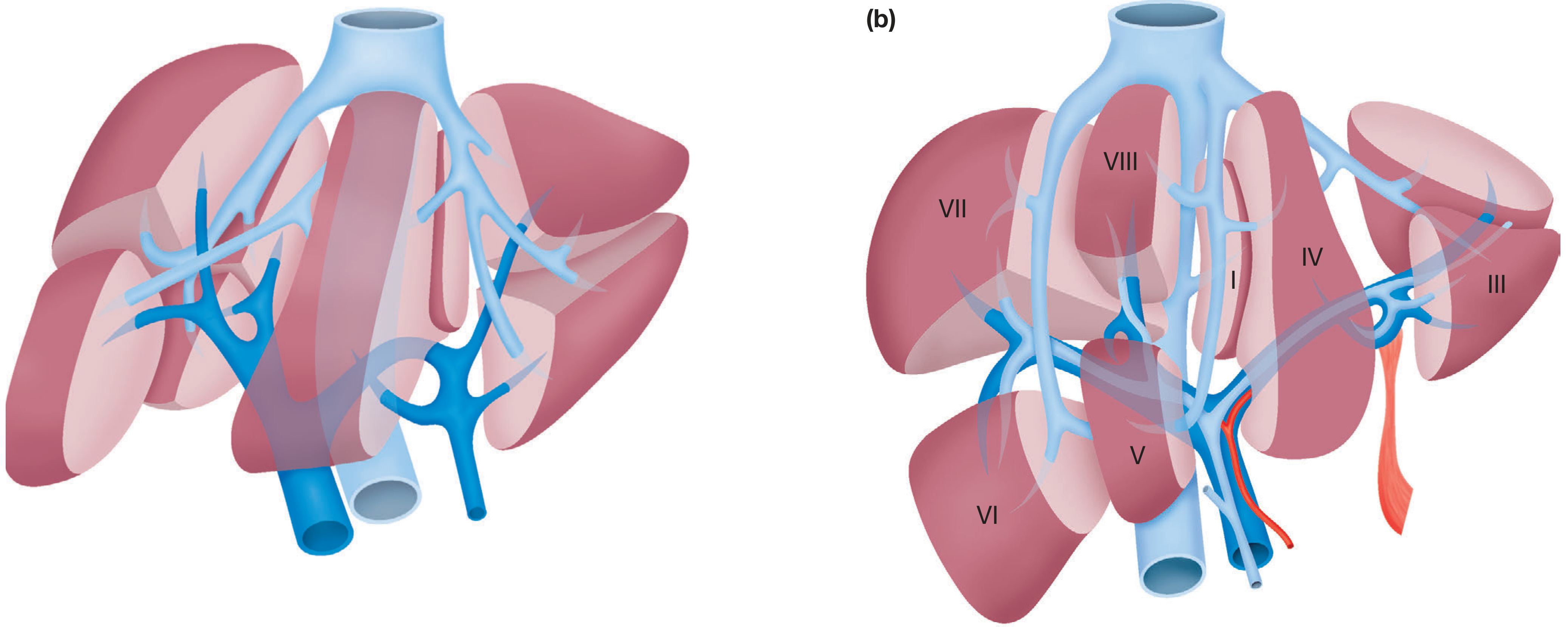
| Segments | Territory |
|---|---|
| I | Caudate lobe (independent drainage to IVC) |
| II, III | Left lateral section |
| IV (IVa, IVb) | Left medial section |
| V, VI | Right posterior inferior |
| VII, VIII | Right posterior/anterior superior |
Surgical relevance: Couinaud's segmental anatomy allows anatomical resections of individual segments with minimal blood loss - critical knowledge for hepatic surgery anaesthesia.
PART 2: PORTAL CIRCULATION & HEPATIC BLOOD FLOW
Dual Blood Supply
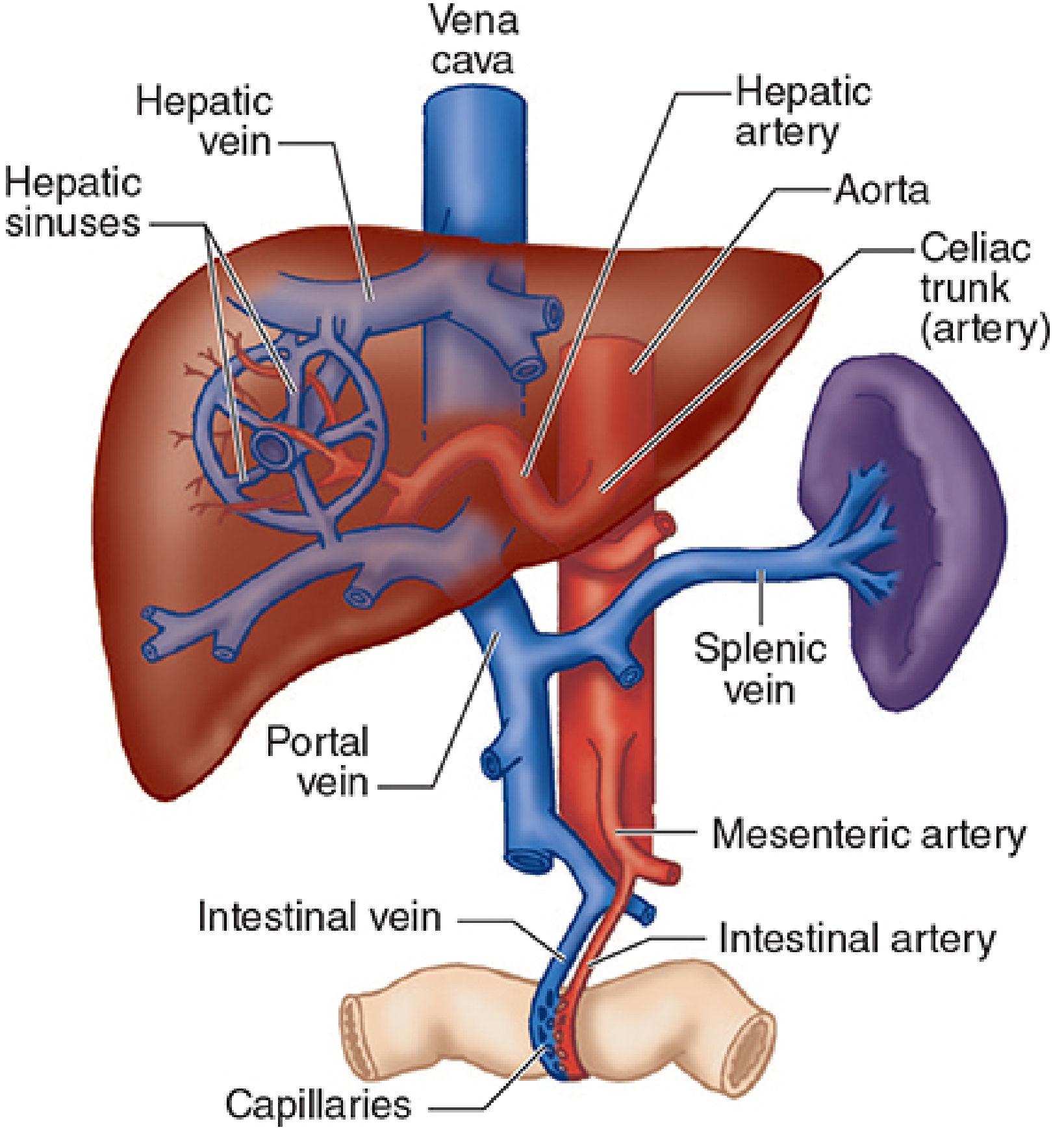
| Vessel | % Blood Flow | % O₂ Delivery | Pressure | Character |
|---|---|---|---|---|
| Portal vein | 70% | 30-50% | 7-10 mmHg | Nutrient-rich, partially deoxygenated |
| Hepatic artery | 30% | 50-70% | Systemic (~90 mmHg) | Oxygenated |
Formation of the Portal Vein
- Superior mesenteric vein (from small bowel + right colon)
- Splenic vein (from spleen; also receives inferior mesenteric vein)
- Stomach, small intestine, large intestine (to splenic flexure)
- Spleen, pancreas, gallbladder
Portal Vein at the Hilum
- Bile duct: anterior right
- Hepatic artery: anterior left
- Portal vein: posterior (largest, posteriormost)
Hepatic Artery Anatomy
- Origin: Coeliac trunk → common hepatic artery → proper hepatic artery (after gastroduodenal artery branches off) → right and left hepatic arteries
- Important variant: Right hepatic artery may arise from superior mesenteric artery (runs behind bile duct) - present in ~20% - critical to identify before clamping/ligating
- Another variant: Left hepatic artery may arise from left gastric artery - present in ~10-15%
Reciprocal (Buffer) Response
Venous Drainage
- Right hepatic vein: drains segments V, VI, VII
- Middle hepatic vein: drains segments IV, V, VIII
- Left hepatic vein: drains segments II, III (and often IV)
- Caudate lobe (segment I): direct small tributaries into IVC - independent of the three main veins
Anaesthesia relevance: Lowering CVP during liver resection (target CVP <5 mmHg) reduces hepatic venous pressure and hepatic blood volume, substantially reducing blood loss. Small changes in hepatic venous tone produce large shifts in blood volume (liver as a reservoir).
Liver as Blood Reservoir
- During haemorrhage: hepatic venous pressure falls → blood is mobilised from hepatic sinusoids into central circulation
- In right heart failure: ↑ CVP → hepatic venous congestion → impaired liver function
- During liver surgery: lowering CVP reduces hepatic blood volume and intraoperative bleeding
PART 3: HISTOLOGY
Overview of Liver Structure
- Hepatocytes - arranged in anastomosing plates (one cell thick in adults)
- Sinusoidal capillaries - between hepatocyte plates
- Perisinusoidal spaces (Space of Disse) - between sinusoidal endothelium and hepatocytes
- Connective tissue stroma - continuous with Glisson's capsule, carries portal tracts
Classic Hepatic Lobule
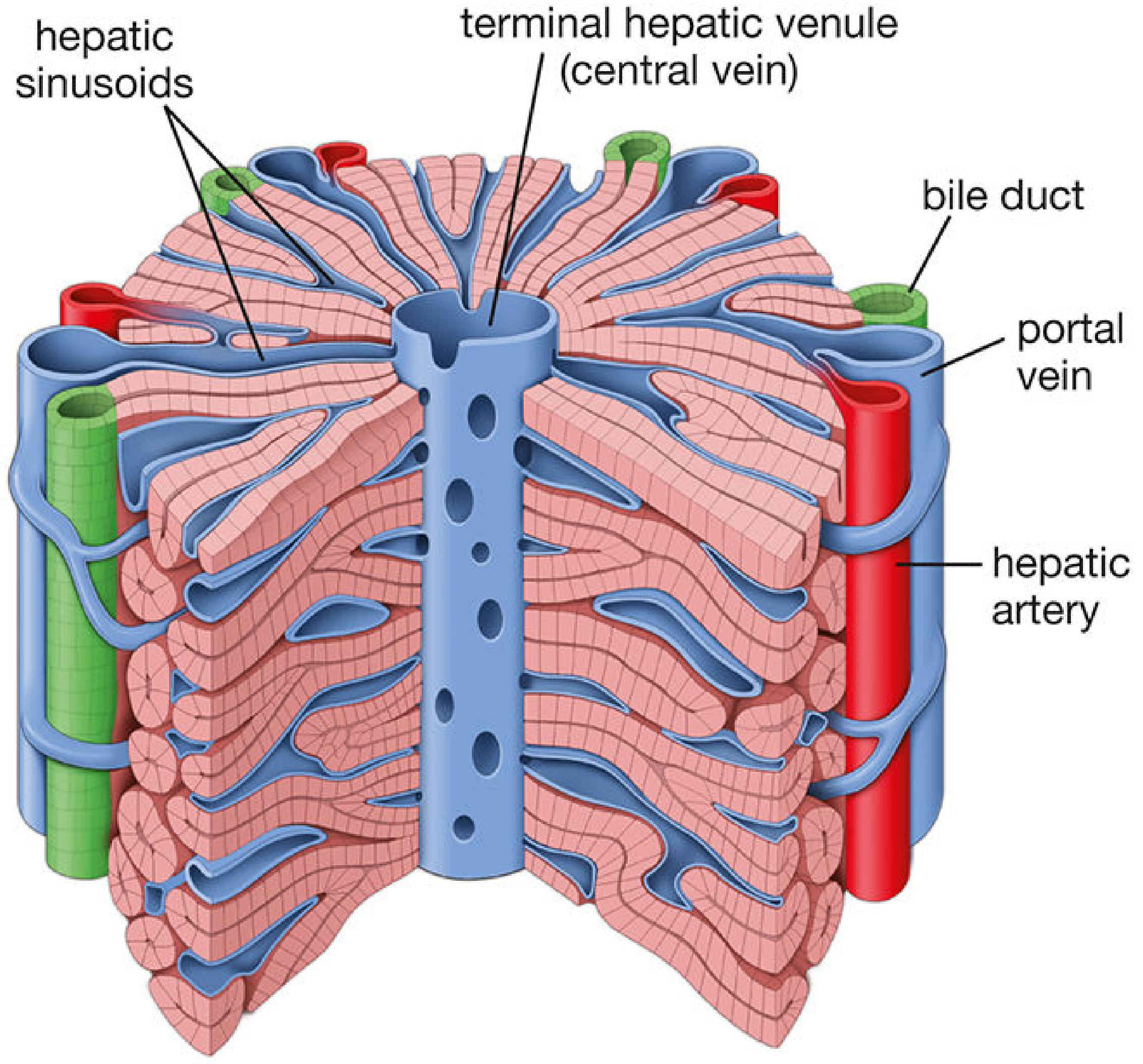
- Centre: Terminal hepatic venule (central vein)
- Periphery (6 corners): Portal triads (portal canals)
- Hepatocyte plates radiate from central vein to periphery, like spokes of a wheel
- Sinusoids run between the plates, draining centripetally into the central vein
- Size: ~2.0 mm × 0.7 mm
Portal Triad (Portal Canal)
| Structure | Contents |
|---|---|
| Portal venule | Branch of portal vein; carries nutrient-rich blood |
| Hepatic arteriole | Branch of hepatic artery; oxygenated blood |
| Bile ductule | Carries bile in opposite direction to blood flow |
| + Lymphatics and nerves |
The Hepatic Lobule Diagram (Full Internal Structure)
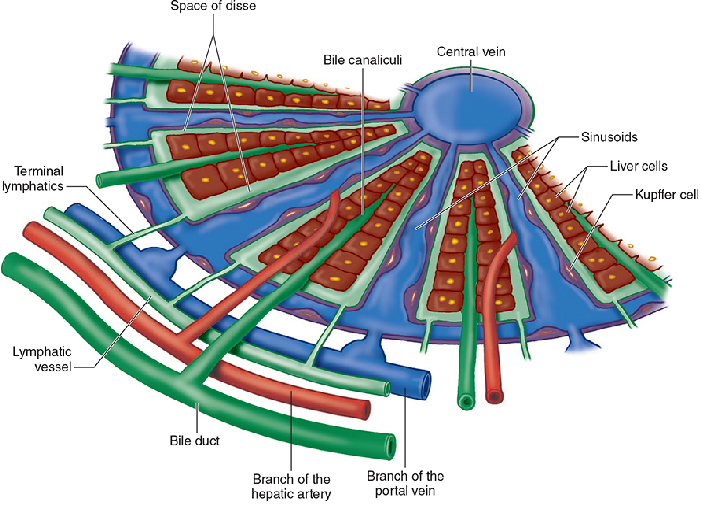
- Portal triad (bile duct + hepatic artery branch + portal vein branch) at periphery
- Sinusoids running radially toward the central vein
- Space of Disse between sinusoids and hepatocytes
- Kupffer cells lining the sinusoids
- Bile canaliculi running between hepatocytes (opposite direction to blood flow)
- Terminal lymphatics
Sinusoids
- The sinusoids are capillaries between the hepatocyte plates
- Blood from portal venules AND hepatic arterioles commingles in sinusoids before flowing to the central vein
- Lined by fenestrated endothelial cells (large pores, no diaphragm - unlike other capillaries)
- Kupffer cells (resident macrophages) are embedded in the sinusoidal lining - remove bacterial endotoxins, viruses, proteins, and particulate matter
Space of Disse
- Perisinusoidal space between the endothelium and hepatocytes
- Contains hepatic stellate cells (Ito cells) - store vitamin A; when activated, produce collagen (fibrosis/cirrhosis)
- The space is in direct communication with lymphatic channels - a major site of lymph formation
Bile Canaliculi
- Form between adjacent hepatocytes within each plate
- Bile flows centrifugally (peripherally, toward bile ducts in portal triads) - opposite direction to blood
- Bile canaliculi → bile ductules → interlobular bile ducts (in portal triads) → right/left hepatic ducts → common hepatic duct
Three Ways to Describe the Functional Unit
| Unit | Centre | Periphery | Best for describing |
|---|---|---|---|
| Classic lobule | Central vein | Portal triads | Traditional description, histology |
| Portal lobule | Portal triad | Central veins | Exocrine (bile secretion) function |
| Liver acinus (Rappaport) | Terminal portal tract (short axis) | Two central veins | Blood flow, oxygenation, toxicology, pathology |
The Liver Acinus - Most Clinically Relevant Unit
| Zone | Location | Oxygenation | Clinical Significance |
|---|---|---|---|
| Zone 1 (periportal) | Closest to portal triad | Best oxygenated | First to show bile stasis changes; last to die with ischaemia; first to regenerate |
| Zone 2 (midzonal) | Intermediate | Intermediate | Intermediate features |
| Zone 3 (centrilobular/perivenous) | Closest to central vein | Least oxygenated | First to undergo ischaemic (centrilobular) necrosis; first to accumulate fat; most sensitive to volatile anaesthetic agents (zone 3 CYP2E1 activity) |
Anaesthesia relevance (Zone 3): Halothane hepatotoxicity and drug-induced hepatocellular injury characteristically cause centrilobular necrosis (zone 3). Reduced hepatic blood flow during anaesthesia further compromises zone 3 hepatocytes.
PART 4: HEPATIC PHYSIOLOGY (MD Anaesthesia Focus)
Metabolic Functions
| Function | Detail |
|---|---|
| Carbohydrate metabolism | Converts fructose/galactose to glucose; glycogen storage and release; gluconeogenesis |
| Protein synthesis | Albumin, clotting factors (all except VIII and vWF), alpha/beta globulins, transferrin, haptoglobin, ceruloplasmin |
| Fat metabolism | Fatty acid oxidation, cholesterol synthesis, bile acid synthesis, lipoproteins |
| Hormone metabolism | Converts T4 → T3 (active); degrades insulin, steroids (estrogen, aldosterone, cortisol), glucagon, ADH |
| Vitamin storage | A, B12, D, E, K |
| Drug metabolism | Phase I (CYP450) and Phase II (conjugation) reactions - critical for anaesthesia pharmacology |
| Detoxification | Kupffer cells remove endotoxins; urea synthesis from ammonia |
Coagulation - Key Anaesthesia Knowledge
- Liver synthesises all coagulation factors EXCEPT factor VIII and vWF (produced by endothelium/megakaryocytes)
- Vitamin K-dependent factors: II, VII, IX, X, Protein C, Protein S (remember: "1972")
- Factor VII has the shortest half-life (4-6 h) → PT prolonged first in acute liver failure
- PT/INR measures synthetic function (fibrinogen, prothrombin, V, VII, X)
- Important caveat: INR was designed for warfarin monitoring. In liver disease, anticoagulants (Protein C, S, Antithrombin III) are also reduced → the liver disease patient may be hypercoagulable or hypocoagulable - not simply one direction
Bilirubin Metabolism
- Unconjugated bilirubin released into blood → binds albumin
- Passive hepatic uptake → intracellular binding traps it
- Conjugated with glucuronide in hepatocytes
- Actively excreted into bile canaliculi
Anaesthesia relevance: Postoperative jaundice is most commonly prehepatic (haematoma resorption, haemolysis post-transfusion). Halothane hepatotoxicity is the classic drug cause of hepatic jaundice.
Liver Function Tests - Interpretation for Anaesthesia
| Test | Normal | Measures | Anaesthesia Relevance |
|---|---|---|---|
| ALT/AST (transaminases) | <40 IU/L | Hepatocellular necrosis/inflammation | High = hepatocellular damage, NOT synthetic function |
| Alkaline phosphatase | 25-85 IU/L | Biliary obstruction; also bone | ↑ in cholestasis |
| Serum albumin | 3.5-5.5 g/dL | Chronic synthetic function (t½ = 2-3 weeks) | <2.5 g/dL = chronic liver disease/malnutrition |
| PT/INR | 11-14 s / <1.2 | Acute synthetic function (factor VII t½ = 4-6h) | >3-4 s above control = significant |
| Serum bilirubin | <17 μmol/L | Excretory function | |
| Blood ammonia | 47-65 mmol/L | Hepatic urea synthesis | ↑ = severe hepatocellular damage/encephalopathy |
PART 5: EFFECTS OF ANAESTHESIA ON HEPATIC FUNCTION
Effects on Hepatic Blood Flow
| Agent/Condition | Effect | Mechanism |
|---|---|---|
| All general anaesthesia | ↓ HBF up to 30-40% | ↓ CO, ↓ portal flow, sympathetic activation |
| Surgery near liver | ↓ HBF up to 60% | Sympathetic activation + direct vascular compression |
| Volatile agents (isoflurane) | Maintains HBF relatively well | Vasodilation of hepatic artery |
| Halothane | ↓ HBF most of all volatiles | Portal flow reduction |
| High PEEP / positive pressure ventilation | ↓ HBF | ↓ CO, ↑ hepatic venous back pressure |
| Neuraxial (thoracic epidural) | Increases HBF after abdominal surgery | ↓ sympathetic tone, improved splanchnic flow |
| Laparoscopy/pneumoperitoneum | ↓ HBF | ↑ IAP → portal vein compression |
| Sympathetic activation | ↓ HBF | α1-adrenergic vasoconstriction of hepatic artery and mesenteric vessels |
| β-blockers | ↓ HBF and portal pressure | Block β2 hepatic artery vasodilation |
| Vasopressin | ↓ Splanchnic/portal blood flow | Splanchnic vasoconstriction (used in variceal bleeding) |
| Dopamine | ↑ HBF (at low doses) | D1 receptor vasodilation |
Halothane Hepatotoxicity
- Type I (mild): ~20% of patients; self-limiting transaminase rise; mechanism = reductive metabolism of halothane → free radical intermediates
- Type II (fulminant): 1/10,000-1/35,000; immune-mediated; trifluoroacetyl hapten on hepatocyte proteins triggers immune response; centrilobular necrosis; higher risk with: multiple exposures, female sex, obesity, middle age, family history
Desflurane, sevoflurane, isoflurane: minimal to no direct hepatotoxic effect on hepatocytes.
Opioids and Sphincter of Oddi
- All opioids can cause sphincter of Oddi spasm → ↑ biliary pressure → can mimic biliary colic or confuse intraoperative cholangiography
- Treatment: naloxone or glucagon (relieves spasm)
- Fentanyl causes less spasm than morphine; pethidine (meperidine) has the least effect
Neuroendocrine Stress Response
- Regional anaesthesia (neuraxial) has the most blunting effect on this response
- Deep general anaesthesia and sympathetic blockade have a partial effect
Postoperative Jaundice - Classification
| Type | Cause |
|---|---|
| Prehepatic (most common) | Haematoma resorption, transfusion haemolysis, senescent RBC breakdown |
| Hepatic | Pre-existing liver disease, ischaemia/hypoxaemia, halothane, drug reactions, Gilbert syndrome |
| Posthepatic | Bile duct injury, retained CBD stone, pancreatitis, cholecystitis |
Portal Hypertension & Cirrhosis - Anaesthesia Implications
| System | Effect |
|---|---|
| Coagulation | ↓ all clotting factors (except VIII), ↓ platelets (hypersplenism), ↑ PT/INR |
| Pharmacokinetics | ↓ albumin → ↑ free drug fraction; ↓ CYP450 → ↓ drug metabolism; ↑ Vd (ascites) |
| Cardiovascular | Hyperdynamic circulation (high CO, low SVR); portopulmonary hypertension; hepatopulmonary syndrome |
| Renal | Hepatorenal syndrome; sodium and water retention |
| Respiratory | Pleural effusion (hepatic hydrothorax); restricted diaphragm (ascites) |
| Encephalopathy | ↑ NH3; opioids/benzodiazepines worsen it |
| Drug metabolism | Avoid hepatically-metabolised drugs or reduce doses |
QUICK EXAM SUMMARY
- 4 morphological lobes (right, left, caudate, quadrate); 8 Couinaud surgical segments
- Falciform ligament = anatomical left/right division; Cantlie's line = true surgical division
- Caudate lobe has independent drainage direct to IVC
- Portal vein = SMV + splenic vein; carries 70% of flow, 30-50% O₂
- Hepatic artery = 30% flow, 50-70% O₂; comes from coeliac trunk
- At porta hepatis: BD (right) - HA (left) - PV (posterior)
- Hepatic arterial buffer response: compensatory ↑ when portal flow drops
- Classic lobule: hexagonal, central vein at centre, portal triads at corners
- Blood flow: portal triad → sinusoids → central vein (centripetal)
- Bile flow: canaliculi → ductules → ducts (centrifugal - opposite to blood)
- Liver acinus zones: Zone 1 = periportal (survives ischaemia longest); Zone 3 = centrilobular (first to die from ischaemia; halothane hepatotoxicity here)
- All GA ↓ HBF 30-40%; surgery near liver ↓ HBF up to 60%
- Low CVP strategy (< 5 mmHg) during hepatic resection reduces blood loss
- Halothane = centrilobular necrosis; des/sevo/iso = minimal hepatotoxicity
- All opioids → sphincter of Oddi spasm → treat with naloxone or glucagon
- INR in liver disease ≠ bleeding tendency (anticoagulants also ↓)
- Coagulation factors made by liver: ALL except factor VIII and vWF
Posterior triangle of neck , IJV , subclavian vein, femoral vein in MD ANESTHESIA
internal jugular vein central line anatomy triangle sternocleidomastoid
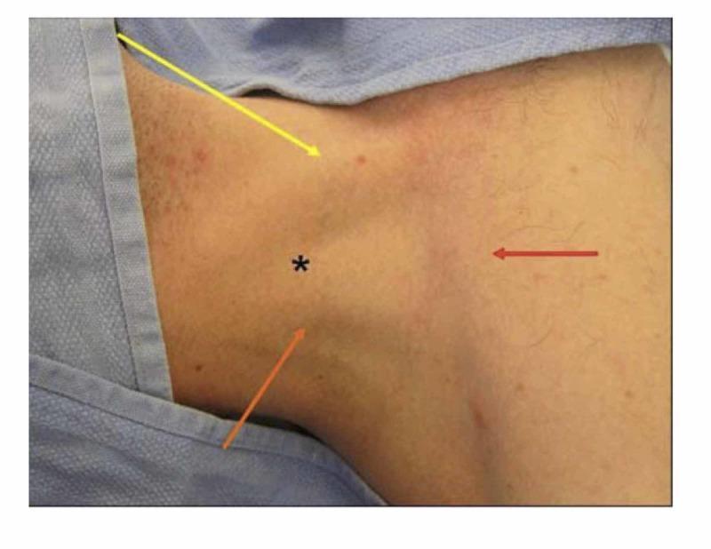
This clinical photograph illustrates the surface anatomy of the neck and superior thoracic region, specifically highlighting the landmarks for central venous catheterization of the internal jugular vein. The image demonstrates Sedillot’s triangle, an anatomical space used for the central approach during puncture. Colored arrows delineate the triangle's boundaries: a yellow arrow indicates the medial border formed by the sternal head of the sternocleidomastoid muscle; an orange arrow indicates the lateral border formed by the clavicular head of the same muscle; and a red arrow marks the inferior border defined by the superior margin of the medial third of the clavicle. A black star designates the apex of this triangle, which serves as the primary anatomical site for cutaneous puncture. The image is an educational resource for medical students and clinicians to visualize critical surface landmarks required for safe vascular access, emphasizing the relationship between muscular structures and the clavicle in critical care and anesthesiology contexts.
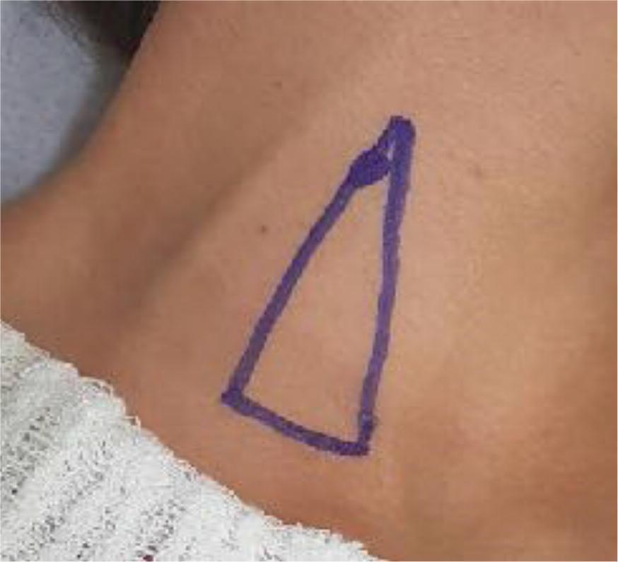
This clinical photograph displays a close-up view of a patient's neck in the dorsal decubitus position, rotated contralaterally to expose the right cervical region. A blue ink marking delineates a triangle representing Sedillot's triangle, an anatomical landmark used for internal jugular vein (IJV) cannulation via the traditional technique (TT). The base of the triangle is situated inferiorly near the clavicle, while the two ascending sides correspond to the sternal and clavicular heads of the sternocleidomastoid muscle. The apex of the triangle is positioned superiorly where these two muscle heads converge. A specific circular mark near the apex indicates the intended puncture point for vascular access, which is clinically localized lateral to the palpated common carotid artery (CCA) pulse. The image serves as an educational guide for identifying superficial anatomical landmarks necessary for central venous catheterization and highlights the surface anatomy used in blind or ultrasound-guided vascular procedures within the field of anesthesiology and critical care.
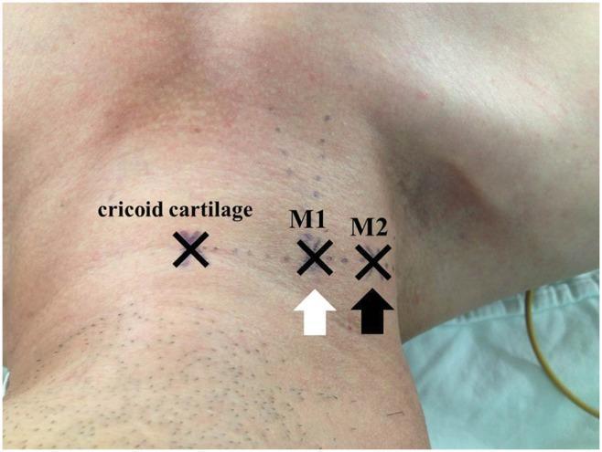
A clinical photograph of the right lateral neck of a patient in a supine, head-down position, demonstrating surface anatomical landmarks for internal jugular vein (IJV) catheterization. Three 'X' markings are visible along a horizontal line at the level of the cricoid cartilage. The leftmost mark indicates the cricoid cartilage itself. The central mark, labeled 'M1' and indicated by a white arrow, represents the apex of the triangle formed by the sternal and clavicular heads of the sternocleidomastoid muscle. The lateral mark, labeled 'M2' and indicated by a black arrow, represents an alternative landmark identified by observing respiratory jugular venodilation and manual palpation of the IJV. The image illustrates the spatial relationship between traditional surface landmarks and dynamic physiological markers (venodilation) used to improve the accuracy of central venous access. Subtle skin elevations near M2 correspond to underlying venous distension, providing clinical guidance for needle insertion in the absence of ultrasound.
Posterior Triangle of Neck, IJV, Subclavian Vein & Femoral Vein - MD Anaesthesia
PART 1: POSTERIOR TRIANGLE OF THE NECK
Boundaries
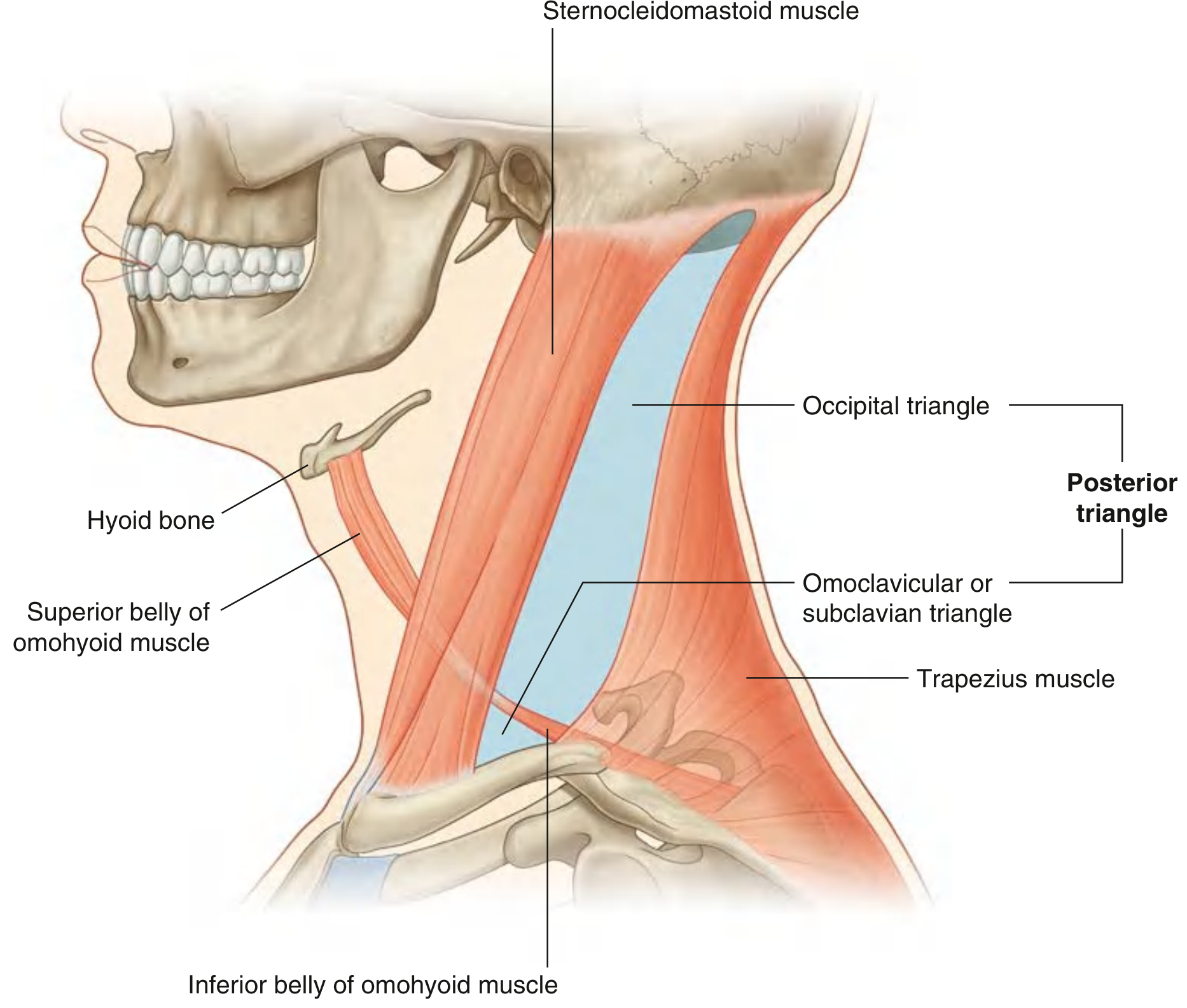
| Boundary | Structure |
|---|---|
| Anterior | Posterior border of sternocleidomastoid (SCM) |
| Posterior | Anterior border of trapezius |
| Base (inferior) | Middle one-third of clavicle |
| Apex (superior) | Occipital bone, just posterior to mastoid process (where SCM and trapezius meet) |
| Roof | Investing layer of cervical fascia (between SCM and trapezius) |
Sub-Triangles
| Sub-Triangle | Location | Key Contents |
|---|---|---|
| Occipital triangle | Superior (larger) | Accessory nerve [XI], cervical plexus, brachial plexus |
| Omoclavicular (Subclavian) triangle | Inferior (smaller) | Subclavian artery (3rd part), subclavian vein, supraclavicular nerves |
Muscular Floor
- Splenius capitis
- Levator scapulae
- Posterior scalene
- Middle scalene (most important - subclavian artery passes between anterior and middle scalene)
- Anterior scalene
Contents - Vessels
| Vessel | Detail |
|---|---|
| External jugular vein | Most superficial; crosses SCM → enters posterior triangle → pierces investing fascia → drains into subclavian vein |
| Subclavian artery (3rd part) | Crosses the base; emerges lateral to anterior scalene → becomes axillary artery at lateral border of rib I |
| Transverse cervical artery | Branch of thyrocervical trunk; crosses base anteriorly |
| Suprascapular artery | Branch of thyrocervical trunk; crosses base |
| Subclavian vein | Just below/at base; anterior to anterior scalene (anterior to the artery!) |
Contents - Nerves
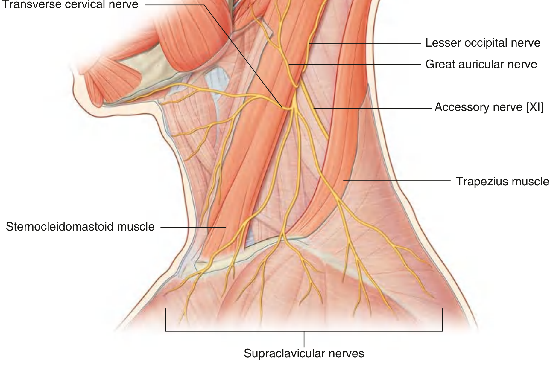
| Nerve | Path | Clinical Significance |
|---|---|---|
| Accessory nerve [XI] | Exits jugular foramen → passes through/behind SCM → crosses posterior triangle obliquely → enters trapezius | Very superficial - at risk during neck dissection and CVC placement |
| Cervical plexus (C1-C4) | Cutaneous branches emerge at posterior border of SCM | Lesser occipital, great auricular, transverse cervical, supraclavicular nerves |
| Phrenic nerve (C3,4,5) | Crosses anterior scalene from lateral to medial → descends into thorax | Risk with supraclavicular brachial plexus block; interscalene block |
| Brachial plexus (C5-T1) | Roots exit between anterior and middle scalene muscles; trunks cross the posterior triangle | Target for interscalene / supraclavicular nerve blocks |
Anaesthesia relevance: The posterior triangle is the approach zone for:
- Interscalene brachial plexus block
- Supraclavicular brachial plexus block
- External jugular vein cannulation
- Subclavian vein (supraclavicular approach)
- Risk of pneumothorax and phrenic nerve palsy with blocks in this region
PART 2: INTERNAL JUGULAR VEIN (IJV)
Anatomy
- Origin: At the jugular foramen in the base of the skull (continuation of sigmoid sinus)
- Course: Descends within the carotid sheath alongside the common carotid artery and vagus nerve
- Relationship: Lies lateral to the common carotid artery (CCA) and internal carotid artery (ICA) in the upper neck; becomes anterolateral to CCA in the lower neck
- Termination: Joins the subclavian vein behind the medial end of the clavicle (medial to anterior scalene) → forms the brachiocephalic (innominate) vein
The Sedillot Triangle (IJV Cannulation Landmark)
| Border | Structure |
|---|---|
| Medial border | Sternal head of SCM (yellow arrow) |
| Lateral border | Clavicular head of SCM (orange arrow) |
| Base (inferior) | Superior margin of medial third of clavicle (red arrow) |
| Apex (★) | Convergence of two heads - needle insertion point |
Approaches to IJV Cannulation
| Approach | Needle Entry Point | Direction | Preferred |
|---|---|---|---|
| Central (most common) | Apex of Sedillot's triangle (between two heads of SCM, at level of thyroid cartilage) | 30-45° toward ipsilateral nipple | Yes - most used |
| Anterior | Anterior border of SCM, at the level of thyroid cartilage | Toward ipsilateral nipple at 30-45° | Used |
| Posterior | Posterior border of SCM at junction of upper and middle thirds | Toward suprasternal notch | Less common |
Patient Positioning for IJV
- Trendelenburg (15-20°): Distends the vein, reduces air embolism risk
- Head turned 30-45° to opposite side: Straightens the vessel, displaces it from behind SCM
- Avoid excessive rotation (>45°) - compresses the vein
Advantages of IJV (for MD Anaesthesia Exams)
| Advantage | Detail |
|---|---|
| Lower pneumothorax risk (~0.5%) vs. subclavian (~1.5%) | Lung apex not in the needle path |
| Compressible if arterial puncture occurs | External pressure can be applied |
| Right IJV preferred | Straight, direct route to SVC → right atrium; no angulation |
| Good for Swan-Ganz catheter | Direct path to right heart |
| Suitable for temporary pacemaker wires | Same reason |
Disadvantages of IJV
- Difficult in short/obese necks
- Carotid artery puncture risk
- Uncomfortable for patients (neck area)
- Infection/thrombosis risk higher than subclavian for long-term use
- Left IJV: risk of thoracic duct injury (chylothorax)
Depth to SVC-RA Junction (Formula - Fischer's)
| Side | Vessel | Formula |
|---|---|---|
| Right | IJV | H/10 (cm), where H = height in cm |
| Right | Subclavian | H/10 - 2 |
| Left | IJV | H/10 + 4 |
| Left | Subclavian | H/10 + 2 |
Structures at Risk with IJV Cannulation
| Structure | Complication |
|---|---|
| Common carotid artery | Arterial puncture, haematoma, pseudoaneurysm |
| Vagus nerve | Nerve injury (rare) |
| Sympathetic chain | Horner's syndrome (rare) |
| Thoracic duct (left) | Chylothorax |
| Lung apex | Pneumothorax (less common than subclavian) |
| Accessory nerve | Nerve injury (posterior approach) |
PART 3: SUBCLAVIAN VEIN
Anatomy
- Continuation of axillary vein from the lateral border of rib I
- Crosses the anterior surface of the anterior scalene muscle (the artery passes posterior to it - this is the key anatomical fact: vein is anterior to the anterior scalene, artery is posterior to it)
- Passes over rib I in the omoclavicular triangle, anterior to the anterior scalene muscle
- Joins IJV behind the medial end of the clavicle to form the brachiocephalic vein
- The vein is held patent by its attachment to the deep surface of the clavicle and the investing fascia - it does not collapse, making it accessible
Relationships at Site of Cannulation
| Structure | Position Relative to Subclavian Vein |
|---|---|
| Clavicle | Superiorly (the vein passes behind/below the clavicle) |
| Rib I | Inferiorly |
| Anterior scalene | Posterior (the artery runs behind it; vein runs in front) |
| Subclavian artery | Posterior (separated by anterior scalene) |
| Phrenic nerve | Just posterior (on anterior scalene surface) |
| Brachial plexus | Posterior and lateral |
| Pleura | Inferoposterior - risk of pneumothorax |
Infraclavicular Approach (Classic)
- Patient position: Slight Trendelenburg + shoulder roll (pushes clavicle posteriorly)
- Needle insertion: 1 cm below junction of medial and middle thirds of clavicle
- Direction: Walk under the clavicle, aim toward the suprasternal notch
- Bevel should face caudally to direct catheter away from the IJV toward the SVC
- Advance until blood flashback, then rotate bevel 90° for passage
Supraclavicular Approach (less common)
- Needle insertion: 1 cm lateral to SCM and 1 cm above the clavicle, in the omoclavicular triangle
- Aimed at the junction of subclavian vein and IJV
- Shorter path; some advantages in mechanically ventilated patients
Advantages of Subclavian Vein
| Advantage | Detail |
|---|---|
| Most comfortable for long-term access | Away from neck movements |
| Lowest infection rate of all CVC sites | Least CLABSI risk; preferred for long-term catheters, PICC, implanted ports |
| Consistent anatomy | Vein does not collapse |
| Suitable when neck immobilised | Trauma, C-spine injury |
| Good for long-term parenteral nutrition |
Disadvantages of Subclavian Vein
| Disadvantage | Detail |
|---|---|
| Highest pneumothorax risk | 1.5% (vs IJV 0.5%) |
| Non-compressible if arterial puncture | Clavicle prevents direct pressure → haematoma |
| Haemothorax risk | |
| Risk of pinch-off syndrome | Catheter compressed between clavicle and rib I |
| Lower success rate in obese/short neck | |
| Absolute contraindication: unilateral lung pathology | Contralateral pneumothorax would be fatal |
PART 4: FEMORAL VEIN
Anatomy
Femoral Sheath Contents (Lateral to Medial)
| Compartment | Contents |
|---|---|
| N - Nerve | Femoral nerve (outside the sheath, lateral compartment) |
| A - Artery | Femoral artery (intermediate compartment) |
| V - Vein | Femoral vein (medial compartment) |
| Y - lymphatics (empty space) | Femoral canal (most medial - potential for femoral hernia) |
The femoral vein is medial to the femoral artery and lateral to the femoral canal.
Surface Anatomy for Femoral Vein Cannulation
- ASIS to pubic tubercle = inguinal ligament
- Midpoint of inguinal ligament = femoral artery pulse
- Femoral vein = 1-2 cm medial to femoral artery pulse, below inguinal ligament
- Insert needle 1-2 fingerbreadths below the inguinal ligament, medial to the femoral arterial pulse
- Direction: 30-45° angle, aimed cranially
Advantages of Femoral Vein
| Advantage | Detail |
|---|---|
| Easiest and fastest access | Vein large; artery always palpable as landmark |
| No pneumothorax / no haemothorax risk | Away from chest |
| Preferred in emergency (cardiac arrest, trauma) | No need to interrupt CPR |
| Safe with coagulopathy (compressible) | Direct pressure can be applied |
| Alternative when neck/chest access impossible | Trauma, burns, previous bilateral CVC failure |
Disadvantages of Femoral Vein
| Disadvantage | Detail |
|---|---|
| Highest infection rate (CLABSI) | Groin colonisation with gut flora; avoid if possible in ICU |
| Highest DVT rate | Up to 15% symptomatic DVT; embolic risk |
| CVP measurement inaccurate | Too far from right atrium |
| Mixed venous O₂ (SvO₂) unreliable | Reflects lower body, not global; cannot use for DO₂ assessment |
| Limited mobility / patient discomfort | |
| Contraindicated if abdominal/pelvic pathology | IVC thrombosis, trauma to iliac vein |
PART 5: COMPARATIVE TABLE (MD ANAESTHESIA EXAM FAVOURITE)
| Feature | IJV | Subclavian | Femoral |
|---|---|---|---|
| Preferred approach | Right central | Infraclavicular | Below inguinal ligament |
| Pneumothorax | 0.5% | 1.5% (highest) | None |
| Infection risk | Intermediate | Lowest (long-term) | Highest |
| DVT risk | Low | Low | Highest |
| Arterial puncture | Carotid (compressible) | Subclavian (non-compressible!) | Femoral (compressible) |
| CVP accuracy | Excellent | Excellent | Poor (too distal) |
| SvO₂ reliability | Good | Good | Poor |
| Emergency access | Good | Difficult in arrest | Best (CPR uninterrupted) |
| Coagulopathy | Caution | Avoid | Preferred |
| Long-term/TPN | Acceptable | Preferred | Avoid |
| Ultrasound guidance | Strongly recommended | Recommended | Recommended |
| Thoracic duct (left) | At risk | At risk | Safe |
PART 6: SELDINGER TECHNIQUE (Common to All Sites)
- Position patient appropriately (Trendelenburg for IJV/subclavian)
- Prep and drape; ultrasound to identify vessel in-plane
- Infiltrate local anaesthetic
- Insert finder needle (22G) - confirm venous blood (non-pulsatile, dark)
- Insert introducer needle (18G) - confirm venous blood
- Pass J-tipped guidewire through needle (no resistance should be felt); confirm on ECG if available (P-wave morphology changes if wire in RA)
- Remove needle over guidewire (never let go of guidewire!)
- Dilate tract with dilator
- Thread catheter over guidewire to appropriate depth
- Remove guidewire; flush and aspirate all lumens
- Secure catheter; apply dressing
- Confirm position with chest X-ray (tip at cavo-atrial junction, no pneumothorax)
PART 7: COMPLICATIONS OF CENTRAL VENOUS CATHETERS
Immediate / Technical
| Complication | Risk Factors | Comment |
|---|---|---|
| Pneumothorax | Subclavian > IJV | Commonest technical complication; risk ↑ 6x with ≥3 attempts |
| Arterial puncture | All sites | If dilator/catheter inserted into artery - DO NOT REMOVE, seek surgical help |
| Haematoma | Coagulopathy, multiple attempts | IJV/femoral compressible; subclavian non-compressible |
| Air embolism | Any site | Trendelenburg position prevents it; treat with Durant manoeuvre + aspiration |
| Haemothorax | Subclavian | |
| Guidewire loss | Careless technique | Never let go of the guidewire |
| Cardiac arrhythmias | Guidewire too far | Wire irritates right ventricle → VT; watch ECG during insertion |
| Thoracic duct injury | Left IJV, left subclavian | Chylothorax |
Air Embolism Management (Classic Exam Question)
- Clamp catheter immediately
- Left lateral decubitus + Trendelenburg (Durant's manoeuvre) - traps air in right ventricle away from pulmonary outflow
- Aspirate air through catheter
- 100% O₂
- Cardiopulmonary resuscitation if cardiovascular collapse
- Hyperbaric oxygen if available
Late Complications
| Complication | Detail |
|---|---|
| CLABSI | ≥48h in situ; organisms migrate from skin or hub contamination |
| Catheter thrombosis | Up to 15%; treat with anticoagulation |
| Catheter malposition | Tip in azygous, internal mammary, contralateral brachiocephalic; verify on CXR |
| Pinch-off syndrome | Subclavian only; catheter compressed between clavicle and rib I |
| Catheter fracture / embolism | Remove under fluoroscopy |
CLABSI Prevention Bundle (CDC/AHRQ)
- Hand hygiene
- Maximal sterile barrier (full gown, gloves, mask, cap, large drape)
- Chlorhexidine skin prep (>0.5% in >70% alcohol)
- Optimal site selection (avoid femoral when possible)
- Daily review of necessity + remove when no longer required
QUICK EXAM SUMMARY
- Borders: SCM (anterior), Trapezius (posterior), Clavicle (base)
- Subdivided by omohyoid → occipital (large, superior) + omoclavicular/subclavian triangle (small, inferior)
- Key nerves: Accessory [XI] (most vulnerable), cervical plexus, phrenic nerve on anterior scalene, brachial plexus between scalenes
- Key vessel: Subclavian artery (3rd part) at base; subclavian vein anterior to anterior scalene
- Sedillot's triangle (central approach); apex = needle entry point, lateral to carotid pulse
- Right side preferred (straight path to SVC)
- Lowest pneumothorax of the three sites
- Depth formula: H/10 cm (right IJV); H/10+4 (left IJV)
- Vein is anterior to anterior scalene; artery is posterior to it
- Highest pneumothorax risk (1.5%); non-compressible artery = dangerous if arterial puncture
- Lowest long-term infection rate → preferred for TPN, long-term CVC
- Formula: H/10-2 (right); H/10+2 (left)
- NAVY: Nerve-Artery-Vein-lymphatics (lateral to medial)
- Best for emergency/coagulopathy; NO pneumothorax
- Highest infection and DVT rate; CVP and SvO₂ unreliable
- Never first choice in ICU