
Fracture in detail in surgery SRB
fracture classification types transverse oblique spiral comminuted
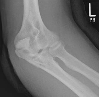
A diagnostic radiograph (X-ray) of the left elbow in an oblique view, demonstrating a comminuted fracture of the proximal ulna involving the olecranon process. The image reveals at least two distinct fracture lines, resulting in a multi-fragmentary pattern. A primary transverse fracture line extends across the olecranon, accompanied by distraction and displacement of the proximal fragment. A second fracture line indicates the presence of an intermediate fragment, which compromises the articular surface of the trochlear notch. The fracture pattern suggests a loss of structural integrity of the elbow's primary bony stabilizer against posterior displacement. Key anatomical landmarks visible include the distal humerus, the coronoid process of the ulna, and the radial head. This imaging illustrates the difficulty in detecting specific intermediate 'key' fragments using conventional biplanar radiography alone, highlighting the clinical relevance of orthopedic assessment for joint congruity and surgical planning.
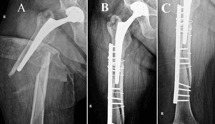
A set of three orthopedic radiographs (X-rays) illustrating a periprosthetic femoral fracture (PFF) and its subsequent surgical management. Panel A shows a preoperative view of a femur with an indwelling total hip arthroplasty (THA) prosthesis. A comminuted, spiral-oblique fracture is visible originating at the level of the trochanteric massif and extending distally beyond the prosthetic stem tip. A large, detached 'butterfly' fragment is present, indicating significant instability (consistent with Vancouver classification). Panels B and C provide postoperative anteroposterior and lateral views demonstrating internal fixation. The fracture has been reduced and stabilized using a long, metallic lateral locking plate. Fixation is achieved through a combination of multiple cortical screws distally and several circumferential cerclage cables (wires) proximally, which secure the plate to the bone segments containing the prosthetic stem. This visual provides an educational example of open reduction and internal fixation (ORIF) strategies for complex periprosthetic fractures where the primary prosthesis remains stable.
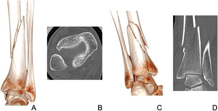
This diagnostic imaging plate provides a side-by-side comparison of two distinct distal tibial fracture patterns using 3D surface reconstructions and axial CT scans. Figures A and B demonstrate a spiral fracture of the tibial diaphysis. The 3D rendering (A) shows the characteristic oblique, twisting fracture line, while the corresponding axial CT scan (B) at the level of the ankle identifies an associated, undisplaced posterior malleolar fracture (PMF), illustrating how spiral shaft injuries can propagate into the articular surface. Figures C and D highlight a different morphology: a comminuted fracture of the distal tibial shaft. The 3D rendering (C) reveals multiple fracture fragments and a medial articular extension towards the ankle joint. The axial CT scan (D) confirms the complex fragmentation and the extension into the distal articular surface. This educational material is designed for orthopedic radiology and trauma surgery training to help differentiate between spiral and comminuted tibial fractures and identify their respective patterns of intra-articular extension, such as posterior malleolar involvement versus medial extension.
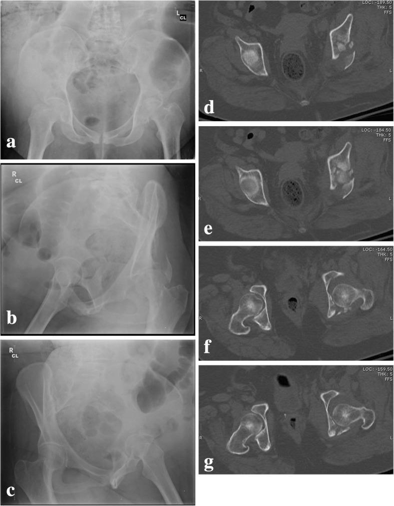
This composite figure presents pre-operative diagnostic imaging of a complex, comminuted transtectal transverse acetabular fracture with posterior wall involvement in a human patient. Panels (a–c) consist of conventional pelvic radiographs: (a) Anteroposterior view showing disruption of the ilioischial and iliopubic lines; (b) Obturator oblique view highlighting the anterior column and posterior wall; and (c) Iliac oblique view visualizing the posterior column and iliac wing. These images demonstrate significant disruption of the normal acetabular architecture and altered joint congruency. Panels (d–g) display axial Computed Tomography (CT) scans at different levels, providing a cross-sectional perspective of the fracture morphology. The CT slices clearly reveal the comminution of the acetabular roof, fracture lines extending through the quadrilateral surface, and displacement of the posterior wall fragments. The imaging collectively illustrates a T-shaped fracture pattern with high-energy articular impaction, serving as a teaching case for the Letournel classification and the assessment of femoral head stability (roof-arc measurements) in orthopedic trauma surgery.
fracture healing stages callus formation bone repair
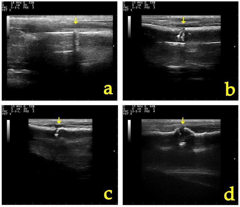
A series of four longitudinal B-mode ultrasound images (labeled a-d) demonstrating the chronological stages of secondary bone healing at a fracture or osteotomy site. The images capture a timeline from post-operative day 0 to day 28. (a) Immediately post-operatively, the fracture site (yellow arrow) shows a distinct hyperechoic cortical discontinuity with acoustic shadowing and heterogeneous surrounding soft tissue. (b) At day 10, early callus formation is visible as hyperechoic material bridging the fracture gap with increased echogenicity of the adjacent periosteal region. (c) By day 20, the callus appears more voluminous and organized, indicating progressive mineral deposition. (d) At day 28, the fracture site shows advanced healing characterized by a mature, more amorphous hyperechoic callus and improved tissue homogeneity, reflecting the consolidation phase of bone repair. This sequence illustrates the clinical utility of musculoskeletal ultrasound in monitoring fracture union, structural organization, and callus maturation over time.
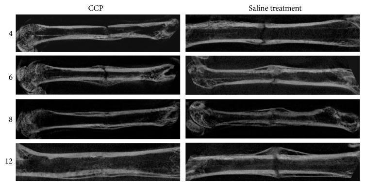
This diagnostic comparison chart displays micro-CT images illustrating the progression of femoral fracture healing in a rodent model over a 12-week period. The visual is organized into two primary columns: the CCP-treated group and the saline-treated (control) group, with rows representing 4, 6, 8, and 12 weeks post-injury. The images highlight key stages of bone repair, including callus formation, bridging, and remodeling. In the CCP group, a progressive increase in callus density and continuity is visible, leading to complete bony union and significant remodeling by week 12, characterized by a smooth, integrated cortical surface. Conversely, the saline-treated group exhibits slower healing, with persistent fracture gaps at early stages and a larger, more irregular callus at week 12. Some control specimens show incomplete bridging and focal defects within the callus. This visual comparison demonstrates the osteogenic potential of CCP treatment in accelerating fracture repair and enhancing bone structural integrity compared to standard physiological healing.
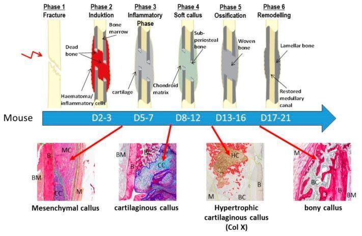
This educational graphic illustrates the six phases of murine (mouse) endochondral fracture healing, combining a longitudinal schematic timeline with corresponding histological sections. Top: A schematic depicts the morphological progression across six stages: Phase 1 (Fracture); Phase 2 (Induction/Hematoma); Phase 3 (Inflammatory/Cartilage formation); Phase 4 (Soft Callus/Sub-periosteal bone); Phase 5 (Ossification/Woven bone bridging); and Phase 6 (Remodeling/Lamellar bone and medullary canal restoration). Center: A blue arrow indicates the timeline in days post-fracture (D2 to D21). Bottom: Four histological micrographs correspond to key biological milestones: 1. Mesenchymal Callus (D2-3): Dense cellular infiltration (MC) adjacent to bone (B) and marrow (BM). 2. Cartilaginous Callus (D5-7): Cartilaginous matrix (CC) characterized by blue-stained chondroid tissue. 3. Hypertrophic Cartilaginous Callus (D13-16): Mineralizing matrix (HC) showing hypertrophic chondrocytes (Collagen X staining) transitioning to bony callus (BC). 4. Bony Callus (D17-21): Mature trabecular structure (BC) with restored marrow spaces and surrounding muscle (M). This content is designed for orthopaedic research and veterinary pathology instruction, highlighting cellular and extracellular matrix transitions during bone repair.
FRACTURE - Detailed Notes (Surgery)
DEFINITION
CLASSIFICATION OF FRACTURES
1. By Aetiology / Cause
| Type | Description |
|---|---|
| Traumatic | Due to direct or indirect force on a normal bone |
| Pathological | Fracture through diseased bone (tumour, osteomyelitis, osteoporosis, Paget's disease) - can occur with minimal/no force |
| Stress / Fatigue | Repetitive submaximal loading at the same site (e.g., march fracture of 2nd metatarsal) |
2. By Skin Integrity
- Closed (Simple): No communication between fracture and exterior
- Open (Compound): Fracture site communicates with the skin surface - risk of infection
3. By Fracture Pattern / Morphology
| Pattern | Description |
|---|---|
| Transverse | Fracture line perpendicular to bone axis; due to direct bending force |
| Oblique | Fracture line at an angle; due to a combination of forces |
| Spiral | Twisting/rotational force; long oblique fracture wrapping around bone |
| Comminuted | More than two fragments; high-energy injury |
| Segmental | Two fracture lines leaving an isolated central bone segment |
| Avulsion | Fragment pulled off by tendon/ligament (e.g., medial malleolus) |
| Impacted | One fragment driven into the other; seen in cancellous bone (femoral neck) |
| Greenstick | Incomplete fracture; cortex fractures on one side with intact periosteal tube - seen in children due to their thicker, more robust periosteum |
| Torus (Buckle) | Compressive buckling of cortex without complete fracture - seen in children |
4. By Location on Bone
- Epiphyseal - involving the bone end and joint
- Metaphyseal - flared region near growth plate
- Diaphyseal - shaft of the bone
OPEN FRACTURE: GUSTILO AND ANDERSON CLASSIFICATION
| Grade | Description |
|---|---|
| I | Low-energy; wound < 1 cm, clean |
| II | Wound > 1 cm; no extensive soft-tissue damage, no flap/avulsion |
| III | High-energy; extensive soft-tissue, muscle, skin, neurovascular damage; highly contaminated; multifragmentary and unstable |
| IIIa | Adequate soft-tissue cover after fracture stabilisation |
| IIIb | Inadequate soft-tissue cover - requires flap coverage |
| IIIc | Open fracture + arterial injury requiring repair |
AO/OTA CLASSIFICATION SYSTEM
- First digit: bone (1 = humerus, 2 = radius/ulna, 3 = femur, 4 = tibia/fibula, etc.)
- Second digit: region (1 = proximal, 2 = diaphysis, 3 = distal)
- Letter: type (A = simple, B = wedge, C = complex/comminuted)
- Final digit: subgroup
SALTER-HARRIS CLASSIFICATION (Growth Plate Injuries in Children)
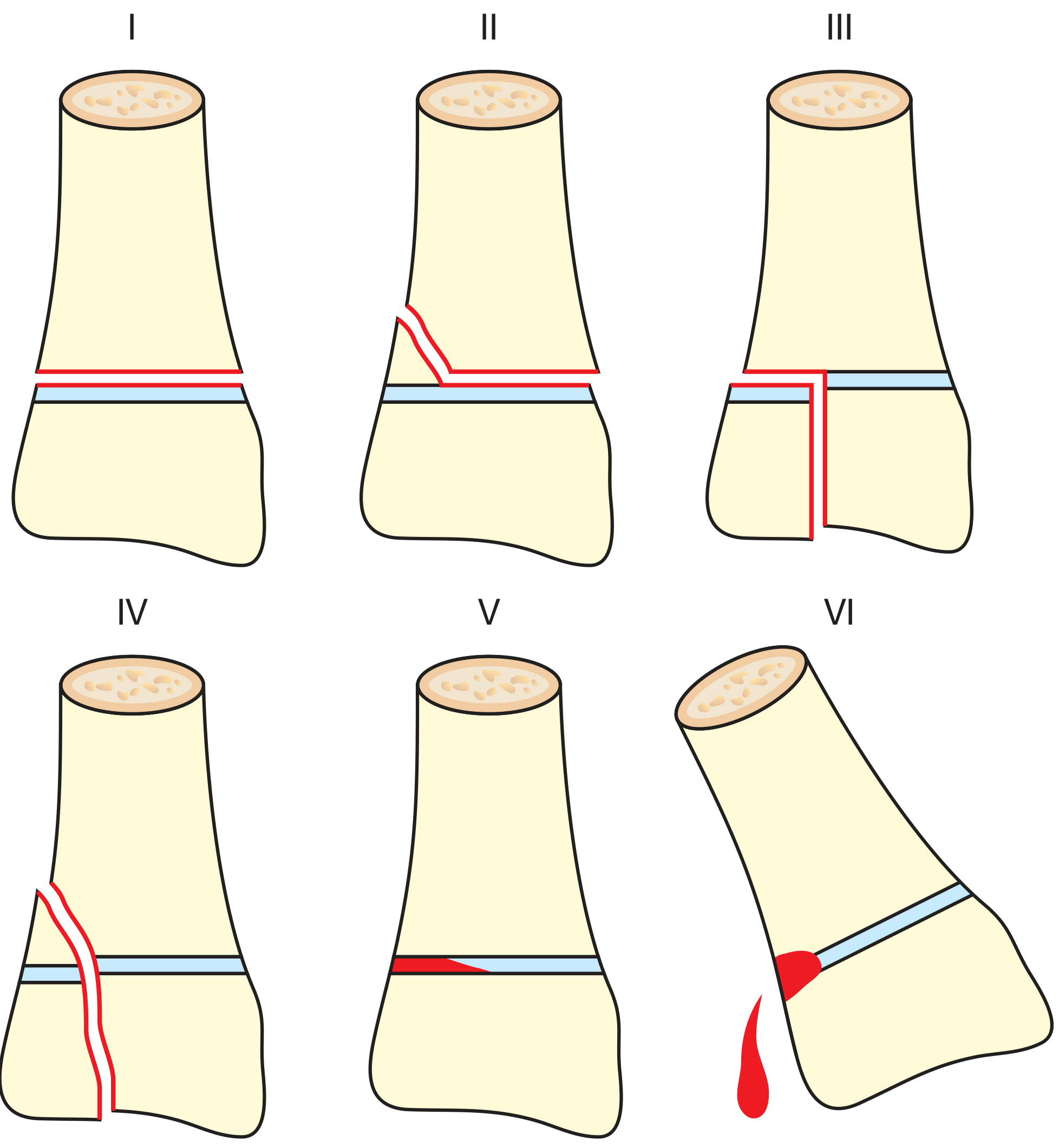
| Type | Description | Growth Risk |
|---|---|---|
| I | Fracture line through physis only | Seldom affected |
| II | Through physis exiting metaphysis (metaphyseal fragment - Thurston Holland fragment) | Seldom affected |
| III | Through physis exiting epiphysis (intra-articular) | Seldom, but articular surface affected |
| IV | Across epiphysis + physis + metaphysis | Can cause focal physis fusion → abnormal growth |
| V | Crush injury of physis | Growth disturbance common; may be first radiological sign |
| VI | Injury to perichondral structures (Mercer Rang addition) | Rare; high chance of abnormal growth |
CLINICAL FEATURES
History
- Mechanism of injury (gives indication of force and likely injury pattern)
- AMPLE mnemonic (ATLS): Allergies, Medications, Past medical/surgical history, Last meal, Events leading to injury
Examination - Systematic Approach
- Look: Swelling, bruising, deformity, shortening, open wound
- Feel: Tenderness, crepitus, neurovascular status
- Move: Active and passive movement
- Special tests and special investigations
Absolute Signs of Fracture
- Deformity
- Abnormal mobility
- Crepitus (pathological)
Relative Signs
- Pain and tenderness
- Swelling
- Bruising/ecchymosis
- Loss of function
INVESTIGATIONS
Radiography - Rule of 2s
- 2 views: Two orthogonal views (AP + lateral) to avoid missing out-of-plane fractures
- 2 joints: Image joint above AND below the fracture
- 2 occasions: Repeat X-ray at 10-14 days if initial X-ray is normal but suspicion persists (classic example: scaphoid fracture)
Other Investigations
- CT scan: Better delineation of complex intra-articular fractures; 3D reconstruction for surgical planning
- MRI: Excellent for occult fractures, soft tissue and ligamentous injuries
- Ultrasound: Useful for soft-tissue assessment; less reliable for bony detail
- Bone scan: Occult/stress fractures, pathological fractures
- Bloods: FBC, clotting, biochemistry in polytrauma; creatinine kinase; blood gas in severe injury
FRACTURE HEALING
Two Mechanisms of Bone Healing
1. Direct (Primary) Bone Healing
- Occurs when fracture ends are in absolute contact with no movement (interfragmentary compression)
- Cutting cones of osteoclasts directly cross the fracture line, followed by osteoblasts laying down new Haversian systems
- Analogous to a wound stitched together - heals directly with no callus formation
- Requires anatomical reduction + rigid fixation (e.g., plates and lag screws)
2. Indirect (Secondary) Bone Healing - The natural biological process
- Occurs with relative stability and micro-movement at the fracture site
- Analogous to wound healing via a scab
- Proceeds through the following stages:
Stages of Indirect (Secondary) Fracture Healing
| Stage | Timing | Description |
|---|---|---|
| 1. Haematoma | Hours - days | Fracture haematoma forms from torn periosteal and medullary vessels. Fibrin scaffold. Growth factors (TGF-β, PDGF, BMPs) released |
| 2. Inflammatory | Days 1-7 | Macrophages, neutrophils migrate in. Angiogenesis begins. Periosteal reaction |
| 3. Soft Callus (Fibrocartilaginous) | Weeks 1-3 | Mesenchymal stem cells differentiate. Cartilage template (endochondral ossification) forms bridging callus. Fracture becomes "sticky" |
| 4. Hard Callus (Ossification) | Weeks 3-12 | Cartilage calcifies; woven bone replaces it. Callus visible on X-ray. Fracture becomes rigid |
| 5. Remodelling | Months - years | Woven bone replaced by lamellar bone. Callus remodelled along lines of stress (Wolff's Law). Medullary canal re-established |
FACTORS AFFECTING FRACTURE HEALING
Local Factors
- Displacement / soft tissue interposition: delays union
- Blood supply: well-vascularised bones heal faster (e.g., scaphoid waist - poor blood supply → avascular necrosis and non-union risk)
- Type of bone: cancellous > cortical bone in healing speed
- Infection: impairs healing, risk of osteomyelitis
- Instability / excessive movement: impairs callus formation
- Bone loss/comminution: large gaps delay or prevent union
Systemic Factors
- Age (children heal faster than adults)
- Nutritional status (Vitamin C, Vitamin D, calcium deficiency)
- Diabetes mellitus
- Steroids and immunosuppressants
- Smoking (impairs vascularity)
- Chronic anaemia
- Radiation
COMPLICATIONS OF FRACTURES
Immediate (at the time of injury)
- Vascular injury - haemorrhage, compartment syndrome, ischaemia
- Nerve injury (neurapraxia, axonotmesis, neurotmesis - Seddon classification)
- Visceral injury (lung, bladder, bowel with relevant fractures)
- Skin damage - open fracture
- Fat embolism
Early (hours to days)
- Haemorrhage and shock
- Compartment syndrome
- Infection (open fractures)
- Deep vein thrombosis / pulmonary embolism
- Crush syndrome
Late (weeks to months)
- Delayed union - healing progresses but slower than expected
- Non-union - healing has ceased without union
- Hypertrophic: adequate blood supply but no stability (elephant foot appearance)
- Atrophic: inadequate blood supply
- Malunion - healed in an abnormal position
- Avascular necrosis - loss of blood supply to a fragment (e.g., femoral head, scaphoid, talus)
- Osteomyelitis - particularly in open fractures
- Post-traumatic arthritis - from intra-articular fractures
- Myositis ossificans - heterotopic ossification in adjacent muscle
- Joint stiffness and contractures
- Sudeck's atrophy (CRPS I)
- Growth disturbance - Salter-Harris injuries in children
- Implant failure / metalwork complications
TREATMENT OF FRACTURES
1. REDUCE
- Determine if reduction is needed: "If the bone healed in this position, would it give optimum function?"
- Intra-articular fractures = anatomical reduction required (to prevent secondary arthritis)
- Extra-articular fractures = mechanical alignment (restoration of length, alignment, rotation)
- Closed reduction: Manipulation under anaesthesia (MUA) - reversing the mechanism of injury, traction + counter-traction
- Open reduction: Surgical exposure - used when closed methods fail, when interposed soft tissue prevents reduction, or when anatomical reduction is mandatory
2. HOLD (Fixation)
- Plaster cast (POP or synthetic)
- Plaster of Paris preferred in acute fractures (easier to mould)
- Backslab (partial cast) used acutely to allow for swelling
- 3-point moulding technique to maintain position
- Functional bracing - allows controlled movement at adjacent joints
| Method | Indication |
|---|---|
| Kirschner wires (K-wires) | Temporary fixation, small bones, supplementing cast; percutaneous or open |
| External fixator | Open/contaminated fractures, damage control, polytrauma, bone loss, periarticular fractures temporarily |
| Intramedullary (IM) nail | Diaphyseal long bone fractures (femur, tibia, humerus); relative stability; allows weight-bearing |
| Plates and screws | Intra/periarticular fractures requiring anatomical reduction; absolute or relative stability possible |
| Arthroplasty | When fragments cannot be held together (e.g., femoral head replacement for subcapital femoral neck fracture in elderly) |
- Absolute stability: No movement at fracture site; compression across fracture; promotes direct bone healing - ideal for intra-articular fractures
- Relative stability: Allows micro-movement; promotes callus and indirect bone healing - ideal for extra-articular fractures
3. HEAL (Monitor union)
- Clinical: pain, swelling, tenderness should reduce
- Radiological: progressive callus formation; bridging callus on 3 cortices = union
- Monitor for complications
4. REHABILITATE
- Early mobilisation to prevent stiffness, DVT, muscle wasting
- Physiotherapy - exercises, gait retraining
- Occupational therapy
- Return to function as the ultimate goal
SPECIAL FRACTURES
| Fracture | Essentials |
|---|---|
| Scaphoid | Most commonly missed; snuffbox tenderness; initial X-ray may be normal - repeat at 10-14 days or MRI; risk of AVN of proximal pole |
| Colles' | Distal radius; "dinner fork" deformity; FOOSH mechanism; dorsal displacement and angulation |
| Smith's | Distal radius; "garden spade" deformity; volar displacement |
| Bennett's | Intra-articular fracture of base of 1st metacarpal; unstable |
| Monteggia | Fracture of proximal ulna + dislocation of radial head |
| Galeazzi | Fracture of radial shaft + dislocation of distal radio-ulnar joint |
| March fracture | Stress fracture of 2nd metatarsal shaft |
| Hangman's fracture | Traumatic spondylolisthesis of axis (C2); hyperextension injury |
| Jefferson fracture | Burst fracture of atlas (C1) |
| Supracondylar | Common in children; risk of anterior interosseous nerve and brachial artery injury |
PERIPHERAL NERVE INJURY ASSOCIATED WITH FRACTURES - SEDDON CLASSIFICATION
| Type | Description | Prognosis |
|---|---|---|
| Neurapraxia | No loss of nerve sheath continuity; no Wallerian degeneration; temporary conduction block | Good - recovers in weeks to months if pressure removed |
| Axonotmesis | Nerve sheath intact but internal fibre damage + Wallerian degeneration; endoneurium guides regeneration | Good - nerve regrows at 1 mm/day |
| Neurotmesis | Complete division of nerve, sheath and fibres | Poor without surgical repair |
FRACTURE-RELATED INFECTION
- A recognized complication of open fractures and surgical fixation
- Diagnosis requires microbiological confirmation
- Management involves surgical debridement, appropriate antimicrobial therapy, and often implant revision
- Can lead to osteomyelitis if inadequately treated
NOTORIOUS MISSED INJURIES (Bailey & Love, Table 32.1)
- Posterior dislocation of the shoulder
- Lateral condylar mass fracture of the distal humerus
- Perilunate dislocation
- Scaphoid fracture
- Tarsometatarsal fracture-dislocation (Lisfranc)
- Compartment syndrome
- Vascular injury with knee dislocation
- Talar neck fracture
- Slipped upper femoral epiphysis (SUFE)
- Achilles tendon rupture
Sources: Bailey and Love's Short Practice of Surgery, 28th Edition (Chapter 32 - Extremity Trauma); Thieme Atlas of Anatomy - General Anatomy and Musculoskeletal System (Section 4.8)
Treatment of fracture
fracture fixation intramedullary nail plate screw external fixator surgical treatment
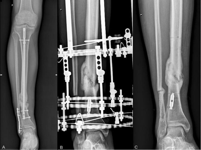
A series of three anteroposterior X-ray radiographs (A, B, C) illustrating the surgical management and progression of a tibial nonunion. Image A (pre-treatment) shows a distal tibia nonunion with existing internal fixation, including an intramedullary nail with proximal and distal interlocking screws and a lateral distal plate. There is visible bone discontinuity and localized sclerosis at the nonunion site. Image B depicts the transition to external fixation using an Ilizarov circular apparatus. The fixator consists of multiple metal rings, connecting rods, and transfixing wires, while bridging callus formation is visible at the fracture site, indicating progress toward secondary bone healing. Image C is a long-term follow-up radiograph six years after the removal of the external apparatus. It demonstrates successful osseous union and bone remodeling, characterized by a thickened cortical bridge at the previous nonunion site. Most previous hardware has been removed, leaving only minimal residual orthopedic hardware in the distal tibia. This clinical sequence highlights the use of distraction osteogenesis and circular fixators in treating recalcitrant long bone nonunions.
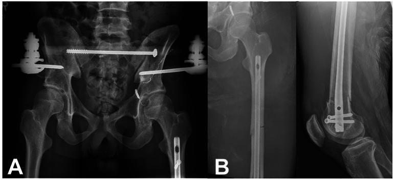
This composite of postoperative orthopedic radiographs includes an AP pelvis (left), AP left femur (middle), and lateral left distal femur (right). Image A displays surgical stabilization of a pelvic ring injury. An anterior pelvic external fixator spans the iliac crests, while posterior pelvic ring stability is achieved via percutaneous sacroiliac (SI) screws traversing the SI joints. Residual widening of the pubic symphysis and left SI joint disruption are visible. Image B demonstrates the treatment of a left segmental femoral shaft fracture using a retrograde intramedullary (IM) nail. The nail is centrally positioned within the medullary canal, spanning the fracture sites. Distal fixation is achieved with transverse locking screws through the distal femur and proximal tibia, and proximal fixation includes a cephalomedullary screw directed toward the femoral head. The radiographs confirm anatomical reduction and restoration of femoral length and alignment following the orthopedic intervention.
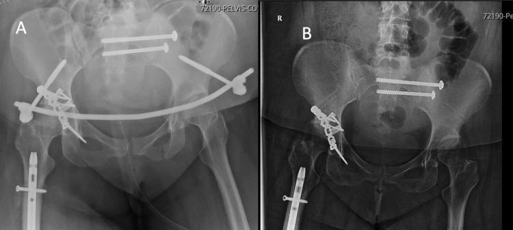
This comparative clinical imaging study consists of two anteroposterior (AP) pelvic X-rays (A and B) demonstrating the surgical management of a complex pelvic ring and acetabular fracture. Image A shows immediate postoperative results with multiple internal fixation devices: two long percutaneous sacroiliac (SI) screws traversing the right SI joint for posterior stability; an anterior subcutaneous pelvic internal fixator (INFIX) consisting of a curved metallic rod connected to pedicle screws in the iliac wings to stabilize the anterior pelvic ring; and a reconstructive plate and screw construct at the right acetabulum. An intramedullary nail with a proximal interlocking screw is also visible in the right femur. Image B shows a follow-up radiograph after the removal of the anterior INFIX rod, while the posterior SI screws, acetabular plating, and femoral nail remain in situ. The images illustrate a staged orthopedic trauma approach, transitioning from temporary flexible anterior stabilization to permanent fixation and subsequent hardware removal once pelvic ring stability is achieved.
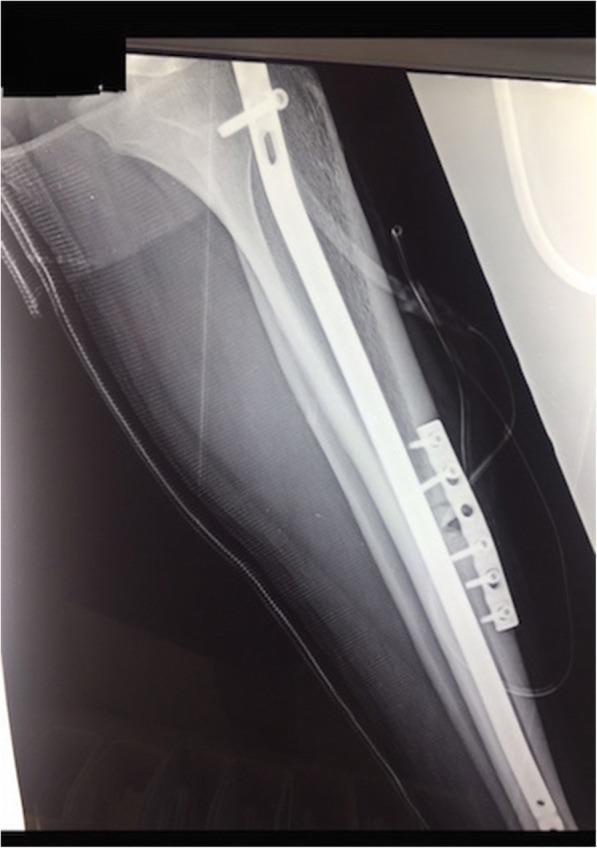
This lateral X-ray of the tibia demonstrates post-surgical management of a stress fracture nonunion using dual fixation hardware. The image shows a long intramedullary (IM) nail positioned within the medullary canal of the tibial shaft, secured proximally by a transverse interlocking screw. Overlaid on the anterior tibial cortex at the site of the fracture is a 6-hole locking compression plate, utilized here for tension band plating. The plate is secured with multiple cortical and locking screws that are angled to avoid interference with the pre-existing IM nail. A visible radiolucent line persists at the anterior cortex, indicating the site of the nonunion. The hardware is intended to provide mechanical stability and compression to promote osteogenesis in a poorly vascularized region. This diagnostic image serves as an educational example of complex orthopedic revision surgery for long bone nonunion and the application of tension band principles in the lower extremity.
TREATMENT OF FRACTURES
FRAMEWORK: APLEY'S 4 PRINCIPLES
REDUCE → HOLD → HEAL → REHABILITATE
STEP 1: REDUCE
When Is Reduction Needed?
| Fracture Type | Reduction Goal |
|---|---|
| Intra-articular | Anatomical reduction - perfect restoration of joint surface to prevent secondary osteoarthritis |
| Extra-articular | Mechanical alignment - restore length, alignment and rotation (not necessarily perfect apposition) |
| Children (extra-articular) | Greater degrees of displacement can be accepted due to remodelling potential |
Methods of Reduction
A) Closed Reduction (Manipulation Under Anaesthesia - MUA)
- No surgical exposure of bone
- Technique: Reverse the mechanism of injury - traction, counter-traction, manipulation
- On occasion, the deformity must first be exaggerated before correcting (to disengage impacted fragments)
- The intact soft-tissue and periosteal hinge is used as a biological aid to reduction
- After reduction, adequacy is checked with fluoroscopy
B) Open Reduction
- Surgical exposure of fracture
- Used when:
- Closed reduction is not achieved or unlikely to succeed
- Soft tissue or interposed muscle prevents reduction
- Anatomical reduction is mandatory (intra-articular fractures)
- Caution: Do NOT strip intact periosteum excessively - this devascularises fracture fragments and impairs healing
C) Combined (Closed + Open)
- Combination of both methods may be used for certain fractures
STEP 2: HOLD (FIXATION)
- Optimise the biological environment for healing
- Optimise the mechanical environment (stability appropriate to healing mode)
- Allow the patient to function as normally as possible
Stability Concepts
| Type | Description | Bone Healing Mode | Ideal For |
|---|---|---|---|
| Absolute stability | No interfragmentary movement; compression across fracture | Direct (primary) bone healing - no callus | Intra-articular fractures |
| Relative stability | Controlled micro-movement at fracture site | Indirect (secondary) healing - callus formation | Extra-articular fractures |
NON-OPERATIVE METHODS
1. Plaster Cast and Splints
- Plaster of Paris (POP): Preferred in acute fractures - easier to mould, conforms to limb shape
- Synthetic casting materials: Lighter, stronger, but less mouldable - used after swelling settles
- Backslab: Partial (half-circumference) cast applied acutely to allow for post-injury swelling; must be accompanied by close clinical observation
- Full cast split along length: Provides full-length support while accommodating swelling
| Advantages | Disadvantages |
|---|---|
| No wound | Limited access to soft tissues |
| No interference with fracture biology | Cumbersome (especially in elderly) |
| Cheap | Interferes with function |
| Adjustable | Poor mechanical stability |
| No implants to remove | "Plaster disease" - joint stiffness and muscle wasting |
2. Traction
- A stretching force applied along the limb axis to pull a fracture back to length and alignment
- Can be manual (temporary, for transfer/manipulation) or sustained via Thomas splint + balanced traction
- Thomas splint with balanced traction = classic management of femoral shaft fractures (now mainly used as temporary pre-operative stabilisation)
- Skin traction: Via adhesive tapes to skin (limited weight, skin complications)
- Skeletal traction: Pin through bone (calcaneum, distal femur, olecranon) - allows heavier weights
| Advantages | Disadvantages |
|---|---|
| No wound in zone of injury | Restricts patient mobility |
| No interference with fracture site | Expensive in hospital time |
| Cheap materials | Skin pressure ulcers |
| Adjustable | Pin site infection |
| Thromboembolic risk |
OPERATIVE METHODS
1. Kirschner Wires (K-wires)
- Smooth or threaded small-diameter metal wires drilled percutaneously or openly into bone
- Left proud of skin (bent over) and removed in clinic at 4-6 weeks
- Temporary or definitive fixation of small fragments
- Temporary fixation pending definitive surgery
- Definitive fixation of small fragments (wrist fractures, hand injuries)
- Tension band wiring of patella and olecranon fractures
- Temporary immobilisation of small joints
2. External Fixator
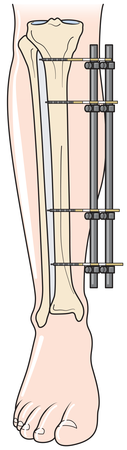
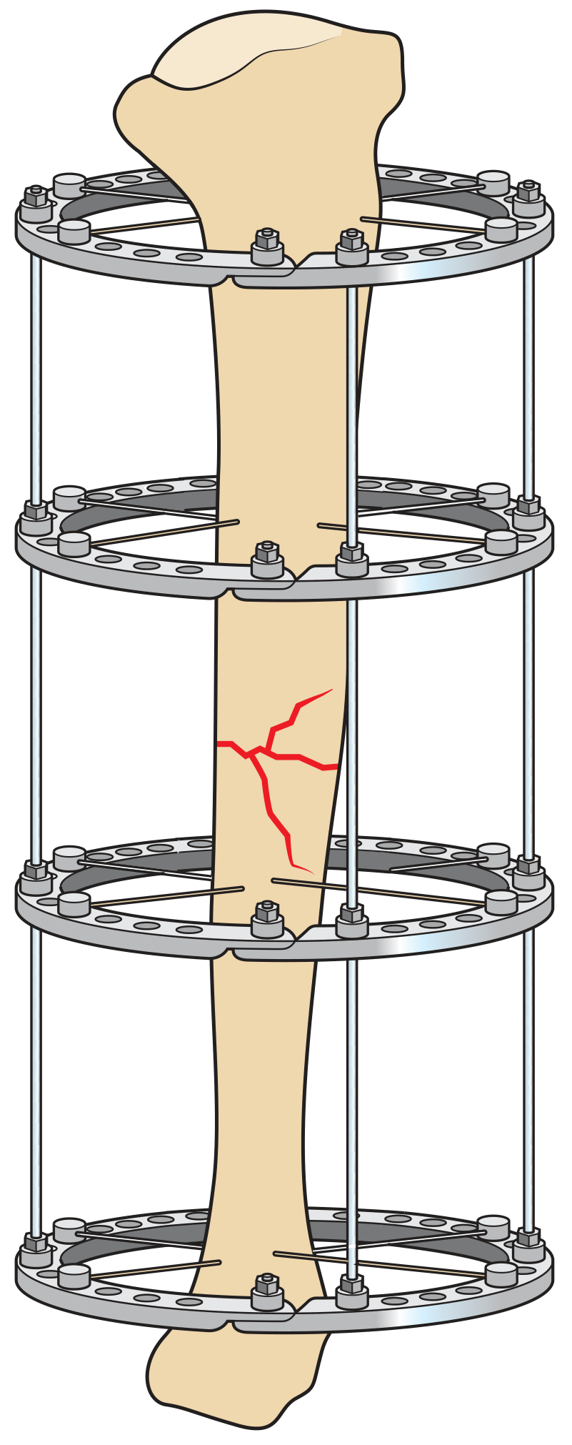
- Metal pins/rods inserted percutaneously into bone above and below fracture, connected to an external metal frame
- Types:
- Unilateral (uniplanar) frame: Simplest; connecting bar on one side
- Ilizarov circular ring fixator: Multiple rings + transfixing wires; used for complex fractures, bone lengthening, deformity correction
- Taylor Spatial Frame: Computer-assisted ring fixator allowing gradual correction of deformity in 6 axes
- Open/contaminated fractures (soft tissues accessible for wound care)
- Damage control orthopaedics - rapid stabilisation in polytrauma patients too unwell for definitive surgery
- Temporary joint-spanning stabilisation (e.g., knee dislocation with arterial injury)
- Complex periarticular fractures - temporary stabilisation while soft-tissue damage recovers before definitive fixation
- Fractures with bone loss
- Fractures associated with infection
| Advantages | Disadvantages |
|---|---|
| No interference with fracture site | Pin site infection |
| Adjustable alignment after application | Interferes with plastic surgical procedures |
| Soft tissues fully accessible | Soft-tissue tethering |
| Rapid stabilisation | Cumbersome for patient |
| Hardware easy to remove |
3. Plates and Screws
- Lag screw: Generates compression across the fracture - optimises environment for direct bone healing
- Dynamic compression plate (DCP): Eccentric screw placement generates compression
- Neutralisation plate: Protects a lag screw from bending/torsional forces
- Buttress plate: Prevents shear and collapse of a metaphyseal fragment
- Locking plate (internal-external fixator): Locking screws thread into plate holes; plate does NOT need to contact bone; allows closed reduction + percutaneous insertion → behaves like an internal external fixator
- Articular and periarticular fractures requiring anatomical reduction (open technique + plates + screws → absolute stability)
- Extra-articular fractures using locking plates (closed, percutaneous, relative stability)
| Advantages | Disadvantages |
|---|---|
| Can achieve anatomical reduction | May interfere with fracture biology |
| Allows early mobilisation | Periosteal/soft-tissue damage |
| Can provide absolute or relative stability | Does not normally allow immediate load-bearing |
| Potential infection | |
| Metalwork complications | |
| May require plate removal |
4. Intramedullary (IM) Nails
- A metal nail/rod inserted down the medullary canal of a long bone
- Proximal and distal locking screws maintain length, alignment, and rotation
- Best suited for diaphyseal fractures (femur, tibia, humerus)
- Provides relative stability → indirect/secondary bone healing via callus
| Feature | Reamed | Unreamed |
|---|---|---|
| Canal widened before nail | Yes | No |
| Nail diameter | Larger | Smaller |
| Cortical blood supply | Disrupted during reaming | Preserved |
| Nail strength | Greater | Lesser |
| Use | Standard for femur/tibia | Contaminated/open fractures |
- Minimally invasive
- Allows early weight-bearing
- Less periosteal damage than ORIF
- Mechanical alignment without anatomical exposure
- Suitable for segmental fractures
- Technically demanding procedure
- Intramedullary reaming disrupts endosteal blood supply
- Risk of fat embolism (reaming)
- Not ideal for articular fractures
- Rotational alignment must be checked carefully
5. Arthroplasty (Joint Replacement)
- Used when fracture fragments cannot be reliably held together OR when the articular surface is so badly destroyed that reconstruction is not feasible
- Examples:
- Hemiarthroplasty (femoral head replacement) for displaced subcapital femoral neck fracture in elderly osteoporotic patients
- Total hip arthroplasty for displaced femoral neck fracture in active elderly patients
- Radial head replacement for comminuted radial head fractures
- Elbow arthroplasty for distal humeral fractures in elderly
- Reverse polarity shoulder arthroplasty for osteoporotic proximal humeral fractures in elderly
INDICATIONS FOR SURGERY (Table 32.11)
- Fracture requiring treatment that is unsuitable for non-operative measures
- Open fractures
- Failed non-operative management
- Multiple injuries / polytrauma
- Pathological or impending pathological fractures
- Displaced intra-articular fractures
- Growth plate fractures at risk of arrest (Salter-Harris types III-V)
- Avulsion fractures compromising functional integrity of a ligament/tendon (e.g., olecranon fracture)
- Established non-unions or malunions
STEP 3: HEAL
- Diabetes mellitus (doubles time to union)
- Diminished blood supply (peripheral vascular disease, vascular injury)
- Smoking
- NSAIDs
- Infection at the fracture site
- Corticosteroids
Methods to Enhance Fracture Healing
| Method | Type |
|---|---|
| Bone marrow injections | Biological (orthobiologics) |
| Bone morphogenetic proteins (BMPs) | Biological |
| Controlled axial micromotion (external fixator) | Mechanical |
| Electromagnetic stimulation | Physical |
| Low-intensity pulsed ultrasound (LIPUS) | Physical |
Monitoring Union
- Clinical: Pain and tenderness progressively diminish; limb can be loaded
- Radiological: Progressive callus formation; bridging callus on 3 of 4 cortices = radiological union
- Time frames (approximate):
- Upper limb: 6-8 weeks (diaphysis)
- Lower limb: 12-16 weeks (diaphysis)
- Cancellous fractures: faster than cortical
STEP 4: REHABILITATE
- Rehabilitation begins as soon as feasible after injury - does not need to wait for full bony union
- Move adjacent joints early: e.g., elbow and shoulder exercises while in a wrist cast (prevents "plaster disease")
- Goals:
- Restore range of movement
- Rebuild muscle strength and bulk
- Restore proprioception and balance
- Return to work and daily activities
- Physiotherapist - exercises, gait training, weight-bearing progression
- Occupational therapist - activities of daily living, splinting, workplace modification
- Surgeon - staged progression of weight-bearing, implant removal when appropriate
RISKS AND BENEFITS OF FRACTURE TREATMENT (Table 32.3)
| Benefits | Risks |
|---|---|
| Pain relief | Anaesthesia |
| Prevention of infection | Introduction of infection |
| Restoration of anatomy | Damage to soft tissues and neurovascular structures |
| Early movement of limb | Devitalising bone |
| Early movement of patient | Need for implant removal |
| Improved function | Financial cost of treatment |
| Reduced risk of secondary arthritis |
MANAGEMENT OF OPEN FRACTURES
- ABCDE - stabilise the patient first (ATLS)
- Wound photograph - document before any dressing
- Saline-soaked dressing + backslab - do not probe wound
- IV antibiotics - co-amoxiclav (or cefuroxime + metronidazole for Grade III); within 1 hour of injury
- Anti-tetanus prophylaxis
- Definitive debridement - within 6 hours for contaminated wounds (Grade III); within 24 hours for low-grade injuries
- Wound closure - primary closure if clean; delayed primary closure or flap coverage if contaminated/Grade IIIb
- Fracture stabilisation - external fixation preferred in contaminated open fractures initially; IM nail or ORIF once wound clean
Source: Bailey and Love's Short Practice of Surgery, 28th Edition, Chapter 32 - Extremity Trauma