x ray tube
Reading File
Finding Sources
Searching the Web
X-ray tube construction components working principle radiology
Finding Sources
Reading Web Page
https://radiopaedia.org/articles/x-ray-tube-1?lang=us
Finding Sources
Reading File
Reading File
Loading Image
Reading Web Page
https://radiologykey.com/the-x-ray-tube-2
Here is a thorough breakdown of the X-ray tube:
X-ray Tube
The X-ray tube is a high-vacuum electronic diode that converts electrical energy into X-ray photons. It was first used by Wilhelm Roentgen in 1895 to produce the first radiographic image.
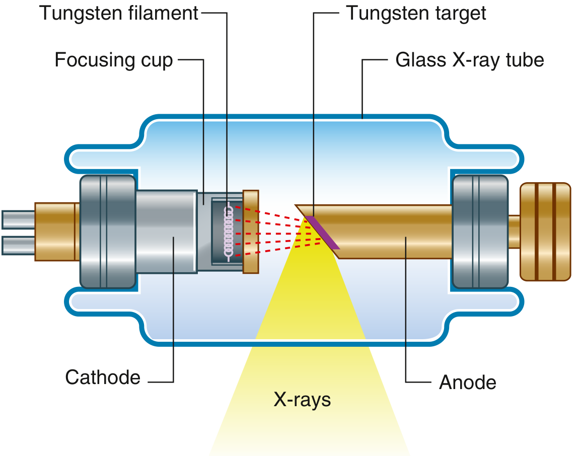
Construction
The general-purpose X-ray tube consists of three major components enclosed in a glass or metal vacuum envelope:
| Component | Description |
|---|---|
| Cathode | Negative electrode; contains a tungsten filament and focusing cup |
| Anode | Positive electrode; contains the tungsten target; rotates in modern tubes |
| Induction motor | Half inside, half outside the envelope; drives anode rotation |
The whole assembly sits inside a protective housing (lead-lined) to contain leakage radiation and provide oil cooling.
Cathode
- Contains a tungsten filament coiled to maximize surface area for electron emission
- Surrounded by a focusing cup (molybdenum), which is negatively charged and electrostatically focuses the electron beam toward the anode target
- When current flows through the filament, it heats up (~2200°C) and releases electrons by thermionic emission
- Tube current (mA) controls the number of electrons (and thus X-ray quantity)
Anode
- The positive electrode, made of a tungsten-rhenium alloy disc embedded in a molybdenum core
- Tungsten is chosen because it has a high atomic number (Z=74) for efficient X-ray production and an extremely high melting point (~3422°C)
- In rotating anode tubes (standard in modern use), the disc spins at ~3000-10,000 RPM to spread heat over a larger focal track rather than concentrating it on one spot
- Stationary anodes are only used in low-output applications (e.g., dental X-ray)
- Angled at typically 5-15° to define the effective focal spot (line-focus principle)
X-ray Production
Two mechanisms generate X-rays when high-energy electrons hit the tungsten target:
1. Bremsstrahlung ("braking radiation") - ~90% of output
- An electron passes close to a tungsten nucleus, decelerates and changes direction
- Kinetic energy is converted to a photon (X-ray) with a range of energies
- Produces a continuous spectrum of X-ray energies
2. Characteristic radiation - ~10% of output
- An incident electron ejects an inner-shell electron from a tungsten atom
- An outer-shell electron drops in to fill the vacancy, emitting a photon of fixed energy
- Produces discrete X-ray energies characteristic of tungsten
Efficiency is very low - only ~1% of energy becomes X-rays; ~99% becomes heat.
Key Parameters and Controls
| Parameter | Controlled by | Effect |
|---|---|---|
| kVp (kilovoltage peak) | Generator voltage | Controls X-ray energy (penetrating power/quality) |
| mA (milliamperes) | Filament current | Controls number of electrons (X-ray quantity) |
| Exposure time | Timer | Controls total dose |
| mAs | mA × time | Total X-ray output |
Important Concepts
Focal spot:
- The actual area on the anode where electrons strike is the actual focal spot
- Due to the angled anode (line-focus principle), the projected area toward the patient is smaller - this is the effective focal spot (desirable for image sharpness)
- Smaller focal spots give sharper images but generate more concentrated heat
Anode heel effect:
- X-ray intensity is not uniform across the beam
- Intensity is lower on the anode side and higher on the cathode side
- Used clinically by placing the thicker part of a body part under the cathode side
Heat management:
- Heat capacity is a major limiting factor in X-ray tube design
- Rotating anodes spread heat over the focal track
- Oil cooling dissipates heat from the housing
- Heat units (HUs) = kVp × mA × time - used to track thermal loading
Clinical Context
The X-ray tube is the core of all plain radiography, fluoroscopy, CT scanning, and cardiac catheterization angiography. In CT, the tube rotates around the patient, typically at 0.3-0.5 seconds per revolution, generating enormous heat loads which is why CT tubes need especially high heat capacity ratings.
- Gray's Anatomy for Students, Fig. 1.2
- Fuster and Hurst's The Heart, 15th Edition, p. 116
- X-ray Production - StatPearls/NCBI
skull radiological positioning
Finding Sources
Searching the Web
skull radiological positioning views PA lateral Towne submentovertex radiography
Finding Sources
Finding Sources
Finding Sources
Reading Web Page
https://radiopaedia.org/articles/skull-towne-view-1?lang=us
Finding Sources
Searching the Web
skull radiograph positions PA Caldwell Waters Towne lateral SMV positioning angles anatomy demonstrated
Reading File
Reading Web Page
https://ce4rt.com/positioning/radiographic-positioning-of-th…
Searching the Web
skull lateral view radiograph positioning OML central ray anatomy shown
Loading Image
Here is a complete guide to skull radiological positioning:
Skull Radiological Positioning
Reference Lines (Essential for all skull views)
Before positioning, understand these key reference lines:
| Line | Abbreviation | Definition |
|---|---|---|
| Orbitomeatal line | OML | From outer canthus of eye to centre of external auditory meatus (EAM) |
| Infraorbitomeatal line | IOML | From inferior orbital margin to EAM (~7-8° below OML) |
| Mentomeatal line | MML | From mental point (chin) to EAM |
| Glabellomeatal line | GML | From glabella to EAM |
| Midsagittal plane | MSP | Vertical plane dividing skull into equal left and right halves |
Standard / Basic Skull Series
1. Lateral View
| Feature | Detail |
|---|---|
| Patient position | Erect or recumbent; side of interest closest to IR |
| Part positioning | MSP parallel to IR; IOML parallel to bottom edge of IR; interpupillary line perpendicular to IR (no rotation) |
| Central ray | Perpendicular to IR; directed to a point 2 cm superior to the EAM |
| SID | 100 cm |
| Anatomy demonstrated | Entire cranium in profile - sella turcica, frontal/parietal/occipital bones, anterior/posterior clinoids, sphenoid wings, floor of anterior/middle cranial fossa, calvarium thickness |
| Used for | Pituitary fossa assessment, raised intracranial pressure (copper-beaten skull), vault fractures |
2. PA (Occipitofrontal, OF) View - 0°
| Feature | Detail |
|---|---|
| Patient position | Erect or prone, facing IR |
| Part positioning | Nose and forehead touching IR; OML perpendicular to IR; MSP perpendicular to IR |
| Central ray | Perpendicular to IR; exits at nasion; no angulation |
| Anatomy demonstrated | Frontal bone, sagittal/coronal sutures, inner skull table, overall cranial contour |
| Evaluation criteria | Equal distance from lateral skull to lateral orbit on both sides (no rotation); petrous ridges fill orbits |
3. PA Axial - Caldwell Method (OF 15°)
| Feature | Detail |
|---|---|
| Patient position | Erect or prone, facing IR |
| Part positioning | Nose and forehead against IR; OML perpendicular to IR |
| Central ray | 15° caudad to exit the nasion |
| Anatomy demonstrated | Frontal bone, frontal/anterior ethmoid sinuses, superior orbital margins, crista galli, greater/lesser sphenoid wings, superior orbital fissures |
| Evaluation criteria | Petrous ridges project into the lower third of the orbits |
| Note | At 30° caudad (exaggerated Caldwell), petrous ridges fall below orbit floors |
4. AP / AP Fronto-Occipital View
| Feature | Detail |
|---|---|
| Patient position | Supine (for trauma patients who cannot be prone) |
| Part positioning | OML perpendicular to IR; MSP perpendicular to IR |
| Central ray | Perpendicular to IR; enters glabella |
| Anatomy demonstrated | Same as PA but with slight magnification due to increased OFD; frontal bone, orbital rims |
| Note | Preferred in trauma when patient cannot be moved to prone |
5. AP Axial - Towne's View (Half-Axial)
| Feature | Detail |
|---|---|
| Patient position | Supine or seated, facing the tube |
| Part positioning | OML perpendicular to IR; chin tucked; MSP perpendicular to IR |
| Central ray | 30° caudad to OML (or 37° caudad if using IOML); directed ~2.5 cm above supraorbital margins, passing through foramen magnum |
| Anatomy demonstrated | Occipital bone, foramen magnum, dorsum sellae and posterior clinoid processes (projected inside foramen magnum), petrous pyramids, petrous ridges, occipital condyles |
| Evaluation criteria | Dorsum sellae centered within foramen magnum; symmetric petrous ridges = no rotation |
| Used for | Occiput fractures, posterior fossa |
6. PA Axial - Haas Method (Reverse Towne)
| Feature | Detail |
|---|---|
| Patient position | Prone (PA direction) |
| Part positioning | OML perpendicular to IR; MSP centred |
| Central ray | 25° cephalad from below; enters 6 cm below external occipital protuberance |
| Anatomy demonstrated | Occipital bone, foramen magnum, posterior clinoids/dorsum sellae within foramen magnum - same as Towne but for patients who cannot lie supine |
7. Occipitomental - Waters View
| Feature | Detail |
|---|---|
| Patient position | Erect or prone, facing IR |
| Part positioning | OML at 37° to IR (chin extended, raised off IR); MML perpendicular to IR; centering to acanthion |
| Central ray | Perpendicular to IR; enters at acanthion |
| Anatomy demonstrated | Maxillary sinuses (best view), frontal sinuses, inferior orbital rims, orbital floors, zygoma and zygomatic arches, nasal septum, maxillae |
| Used for | Midface fractures, sinusitis; in Tintinalli's - "Waters' view safely replaces multiple views in traditional facial series for midfacial fractures" |
8. Submentovertex (SMV) - Schuller Method (Basilar View)
| Feature | Detail |
|---|---|
| Patient position | Supine (neck hyperextended) or seated with head tilted back |
| Part positioning | IOML parallel to IR; MSP perpendicular to IR; vertex on IR |
| Central ray | Perpendicular to IOML; enters between angles of mandible; directed to sella turcica |
| Anatomy demonstrated | Base of skull - sphenoid sinuses, mandible, foramina of skull base, petrous ridges, zygomatic arches, carotid canals, odontoid process |
| Used for | Skull base fractures, zygomatic arch assessment, mandibular condyles |
| Caution | Contraindicated in suspected cervical spine injury; high radiation dose to lens |
Summary Table
| View | Direction | CR Angle | Key Structure Shown |
|---|---|---|---|
| Lateral | Side-to-side | 0° | Sella turcica, vault profile |
| PA (OF 0°) | PA | 0° | Frontal bone, sagittal suture |
| Caldwell (OF 15°) | PA | 15° caudad | Frontal sinus, sphenoid wings |
| AP | AP | 0° | Frontal bone (trauma) |
| Towne's | AP | 30° caudad (OML) | Occiput, foramen magnum |
| Haas | PA | 25° cephalad | Occiput (can't lie supine) |
| Waters | PA | OML 37° from IR | Maxillary sinuses, mid-face |
| SMV | Inferior-superior | 0° to IOML | Skull base, zygomatic arches |
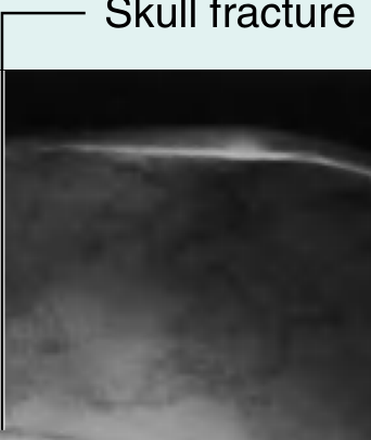
Radiograph: Skull Fracture on Plain Film
Clinical Notes
- Skull X-rays are largely replaced by CT for trauma, but plain radiography is still used in certain trauma settings and resource-limited environments
- For trauma, the standard three views are: lateral, PA, and Towne's - as noted in Gray's Anatomy for Students
- Petrous ridge position on the PA/Caldwell is the key evaluation criterion for correct angulation
- Dorsum sellae within the foramen magnum on Towne's confirms correct positioning
- Always remove hair clips, earrings, and dentures before exposure
- Radiation protection: use a thyroid collar; gonadal shielding where applicable
Sources: Gray's Anatomy for Students; Cummings Otolaryngology; CE4RT Skull Positioning; Radiology Key
This is a shared conversation. Sign in to Orris to start your own chat.