
Breathing system in anesthesia.
Reading File
The breathing system in anesthesia refers to the circuit and components through which gases travel between the anesthesia machine and the patient. It includes the circle system, Mapleson circuits, open/semi-open systems, and components like CO2 absorbers, unidirectional valves, APL valves, and reservoir bags.
Searching sources...
Finding Sources
Finding Sources
Finding Sources
Finding Sources
Finding Sources
Finding Sources
Good - I have strong source hits from Miller's and Morgan & Mikhail. Now let me read the core sections in parallel.
Reading File
Reading File
Excellent content. Now let me get the Mapleson circuits section and CO2 absorber details.
Reading File
Reading File
Reading File
Finding Sources
Finding Sources
Reading File
Now let me fetch the key circuit diagram images to include in the answer.
Loading Image
Reading File
I have comprehensive content from both Miller's Anesthesia (10th ed) and Barash's Clinical Anesthesia (9th ed). Let me now compile the full answer.
Breathing System in Anesthesia
The breathing system (or breathing circuit) is the interface between the anesthesia workstation and the patient. It delivers oxygen and anesthetic vapors to the patient's airway and removes exhaled CO2. Systems are classified based on whether they recycle exhaled gas using a CO2 absorber.
Classification
| Type | Rebreathing | CO2 Absorber | Example |
|---|---|---|---|
| Open | None | No | Open drop ether |
| Semi-open | None/minimal | No | Mapleson circuits (high FGF) |
| Semi-closed | Partial | Yes | Circle system (most common) |
| Closed | Complete | Yes | Circle system (FGF = uptake only) |
1. The Circle Breathing System
The circle system is the most widely used anesthesia breathing circuit in the United States and worldwide. It is named because its components are arranged in a circular, unidirectional manner.
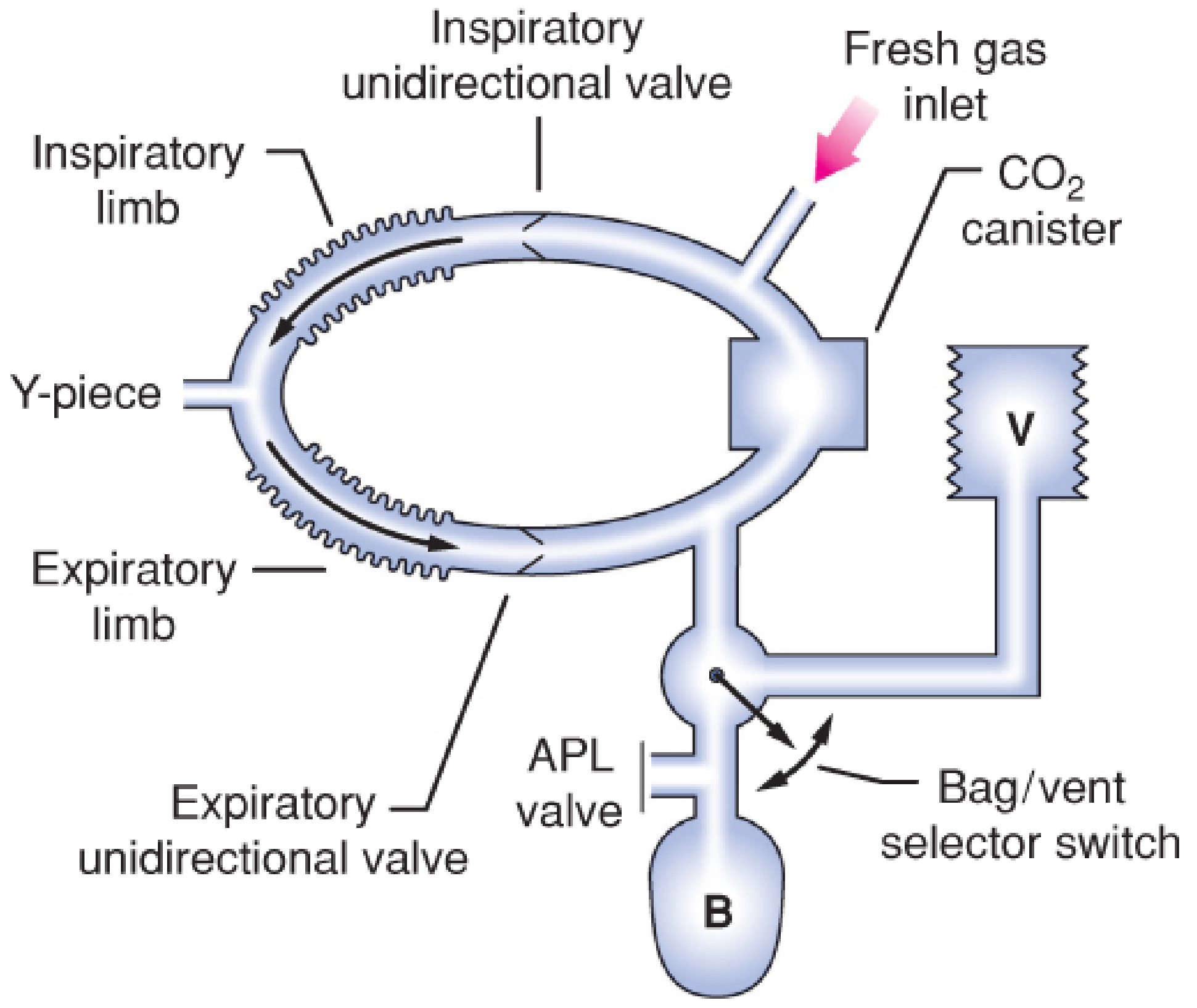
Circle breathing system showing inspiratory and expiratory limbs, Y-piece, APL valve, reservoir bag (B), CO2 canister, and ventilator (V) - Barash, Clinical Anesthesia 9e
Components (7 Primary)
- Fresh gas inflow source - connects from the common gas outlet (CGO) of the workstation
- Inspiratory and expiratory unidirectional valves - ensure one-directional gas flow through the corrugated hoses
- Inspiratory and expiratory corrugated tubes - the two limbs of the circuit
- Y-piece connector - connects both limbs to the patient's airway device
- APL valve (Adjustable Pressure-Limiting / "pop-off" valve) - vents excess gas to the scavenging system
- Reservoir bag - collects gas during expiration; used for manual ventilation
- CO2 absorbent canister - chemically removes CO2 so exhaled gas can be safely rebreathed
Additional safety components: circuit pressure sensor, pressure gauge, inspiratory/expiratory flow sensors, inspired O2 concentration sensor, PEEP valve.
Gas Flow (Inspiratory Phase - Spontaneous)
Gas is drawn from the reservoir bag through the CO2 absorber, mixes with fresh gas inflow, passes through the inspiratory unidirectional valve, and flows to the patient via the Y-piece. The expiratory valve stays closed.
Gas Flow (Expiratory Phase)
Exhaled gas flows back through the Y-piece, through the expiratory unidirectional valve, toward the reservoir bag and APL valve - bypassing the CO2 absorber during exhalation. The inspiratory valve stays closed. This prevents rebreathing before CO2 scrubbing occurs.
Advantages
- Conservation and reuse of anesthetic gases (economy)
- Maintains relatively stable inspired gas concentrations
- Conserves respiratory heat and moisture
- Eliminates CO2 via absorber
- Prevents OR pollution when scavenged properly
Disadvantage
- Complex design with multiple valves (higher risk of malfunction)
- Before administering any anesthetic, the circle system must be checked using a standardized pre-use checklist
2. Modes of Circle System Operation
Determined by the fresh gas flow (FGF) rate:
| Mode | FGF | Rebreathing | Clinical Use |
|---|---|---|---|
| Semi-open | Very high (> MV) | None | Rarely used; wasteful |
| Semi-closed | Intermediate | Partial | Most common in daily practice |
| Low-flow | < 1 L/min | >50% of expired gas | Economy; heat/humidity conservation |
| Minimal-flow | ≤ 0.5 L/min | High | Maximum economy |
| Closed | = Metabolic uptake only | Complete | Closed-circuit anesthesia; rarely used routinely |
Low-flow anesthesia advantages: decreased volatile agent consumption, improved temperature and humidity control, reduced environmental pollution. Disadvantages: difficulty in rapidly changing anesthetic depth, potential accumulation of exhaled gases (CO, acetone, methane) or degradation products (Compound A from sevoflurane). - Miller's Anesthesia 10e
3. CO2 Absorbers
Chemistry - Soda Lime
Net reaction: CO₂ + Ca(OH)₂ → CaCO₃ + H₂O + heat
Sequential reactions:
- CO₂ (gas) + H₂O → H₂CO₃
- H₂CO₃ + 2 NaOH (or KOH) → Na₂CO₃ + 2 H₂O + heat
- Na₂CO₃ + Ca(OH)₂ → CaCO₃ + 2 NaOH* + heat
NaOH/KOH act as catalysts (regenerated in step 3). Soda lime is ~80% Ca(OH)₂ with ~15% H₂O and small amounts of NaOH/KOH.
Lithium hydroxide (LiOH): 2 LiOH·H₂O + CO₂ → Li₂CO₃ + 3 H₂O - does not require NaOH/KOH catalysts.
Volatile Anesthetic Degradation by Absorbents
Compound A (from sevoflurane): Produced by interaction with CO2 absorbents. Risk increases with:
- Low-flow or closed circuit technique
- High sevoflurane concentration
- Higher absorbent temperatures
- Fresh (not exhausted) absorbent
Clinical hepatorenal toxicity is not commonly seen in humans even during low-flow anesthesia.
Carbon monoxide (from desflurane > enflurane > isoflurane >> halothane ≈ sevoflurane): Produced when desiccated strong-base absorbents degrade volatile agents. Key risk factor: machine left running over a weekend desiccates the absorbent. Cases of severe CO poisoning (carboxyhemoglobin up to 35%) have been reported on Monday mornings. - Barash, Clinical Anesthesia 9e
Prevention of CO exposure:
- Turn off anesthesia machine at end of the last case
- Change absorbent if FGF was found flowing during morning check
- Use modern absorbents with reduced/no KOH (e.g., Drägersorb 800 Plus, Amsorb)
4. Mapleson Circuits
Described by William Mapleson in 1954, these are five semiclosed systems (A-E) without CO2 absorbers. A sixth (F) was added by Willis et al. CO2 elimination depends entirely on fresh gas flow washing out exhaled gas.
Components (Common to all)
- Facemask
- Expiratory valve (APL)
- Corrugated reservoir tubing (absent in C)
- Fresh gas inflow tubing
- Reservoir bag (absent in E)
The Six Mapleson Circuits
| Circuit | Also Known As | FGF for Spontaneous | FGF for Controlled | Notes |
|---|---|---|---|---|
| A | Magill circuit | 1× MV (most efficient for spontaneous) | Up to 20 L/min (least efficient) | FGF enters near bag, APL near patient |
| B | - | 1.5-2× MV | ~2.5× MV | FGF near patient |
| C | Waters to-and-fro | ~2× MV | ~2× MV | No corrugated tube; compact |
| D | - | ~2.5× MV | ~2.5× MV | Basis for Bain circuit |
| E | Ayre's T-piece | ~2.5× MV | Controlled not possible | No reservoir bag; used in pediatrics/ICU weaning |
| F | Jackson-Rees circuit | ~2.5-3× MV | ~1.5-2× MV | Mapleson E + open-tail bag; pediatrics/transport |
Functional groups:
- A group - unique behavior (best for spontaneous, worst for controlled)
- B and C group - intermediate
- D, E, F group ("T-piece group") - most commonly used today
The Bain Circuit
A coaxial modification of the Mapleson D system. Fresh gas flows through a narrow inner tube nested inside the outer corrugated hose. Gas exits at the patient's end; exhaled gas passes down the outer hose and is vented through the pop-off valve near the reservoir bag. This arrangement partially warms and humidifies fresh gas. The Bain is the most commonly used Mapleson variant in the United States. - Miller's Anesthesia 10e
Mapleson Advantages Over Circle System
- Low resistance to gas flow
- Small and lightweight (fewer parts)
- Rapid changes in inspired anesthetic concentration
- No risk of anesthetic degradation (no CO2 absorber)
Mapleson Disadvantages
- Higher FGF required - not economical
- Less heat and humidity conservation
- Waste gas scavenging is more challenging
- Risk of rebreathing if FGF is inadequate
5. Pediatric Considerations
The Mapleson E (Ayre's T-piece) and F (Jackson-Rees) circuits are particularly useful in neonates and infants. Even the low resistance of a circle system can impose significant work of breathing on a sick neonate during spontaneous ventilation - unidirectional valves, corrugated tubing, and the CO2 absorber all add resistance. The open T-piece systems are preferred in these situations. - Morgan & Mikhail's Clinical Anesthesiology 7e
6. Key Safety Points
- The circle system must be checked before every use using a standardized pre-use protocol
- High-pressure alarms, continuous positive-pressure alarms (>15 sec), and disconnection alarms (pressure fall for >20 sec during mechanical ventilation) are mandatory per safety standards
- Pressure sensor is typically in the nondisposable inspiratory or expiratory limb near a unidirectional valve; remember this location may not accurately reflect airway pressure
- Absence of the reservoir bag from the circuit facilitates retrograde gas flow and increases absorbent desiccation risk
Sources: Miller's Anesthesia, 2-Volume Set, 10e; Barash, Cullen, and Stoelting's Clinical Anesthesia, 9e; Morgan and Mikhail's Clinical Anesthesiology, 7e
This is a shared conversation. Sign in to Orris to start your own chat.