
Give me a photo of the heart, uh, addressing all the... Um, I mean, all the components, uh, like... Uh, I mean, all the components, uh, like the right atrium, right ventricle, and all the veins, uh, indicating, and also all the, um, groups, and... I mean, all the groups, um, uh, anterior groups, posterior grooves
heart anatomy diagram showing all chambers right atrium right ventricle left atrium left ventricle veins arteries grooves anterior posterior
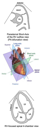
Summary : This figure illustrates anatomical and echocardiographic planes and views of the heart, focusing on the right ventricle (RV) and its outflow tract, as well as the relationship between imaging planes and cardiac anatomy. illustration: # Anatomical Diagrams : • Top diagram: Schematic cross-section showing the anterior heart with the right ventricular outflow tract (RVOT), aorta (Ao), and pulmonary artery (PA) labeled. • Bottom diagram: Schematic of a four-chamber heart view, labeling the right ventricle (RV), left ventricle (LV), right atrium (RA), and left atrium (LA), with lateral orientation indicated. # Echocardiographic Planes : • Central image: 3D anatomical heart model with three intersecting planes labeled: – Long axis plane (blue) – Short axis plane (green) – Apical plane (purple) • Directions labeled: Superior, Inferior, Anterior, Posterior, Medial, Lateral. # View Labels : • Middle annotation: "Parasternal Short-Axis of the RV outflow view (PA bifurcation view)" indicating the imaging plane for visualizing the pulmonary artery bifurcation. • Bottom annotation: "RV-focused apical 4-chamber view" indicating the imaging plane for visualizing all four heart chambers with emphasis on the right ventricle. # Analysis : • The figure demonstrates how different echocardiographic planes intersect the heart to provide specific anatomical views, aiding in the assessment of right ventricular structure and function. The schematic diagrams clarify the orientation and anatomical relationships for each view, supporting accurate imaging and interpretation in clinical practice.
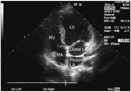
**Imaging Modality:** Transthoracic Echocardiogram (TTE), B-mode ultrasound. **Anatomical Region:** Apical four-chamber (A4C) view of the heart, showing the left atrium (LA), right atrium (RA), left ventricle (LV), and right ventricle (RV). **Observed Pathology:** Cor triatriatum sinistrum. A linear, echogenic membrane is visible within the left atrium, bisecting the chamber into two distinct segments. **Characteristic Visual Features:** * **Intra-atrial Membrane:** A thin, transverse fibromuscular band (indicated by a black arrow) divides the left atrium into a superior/posterior chamber (proximal LA), which receives the pulmonary veins, and an inferior/anterior chamber (distal LA), which communicates with the mitral valve and left ventricle. * **Chamber Morphology:** The four cardiac chambers are labeled (LV, RV, RA, LA) to orient the segmental anatomy. * **Key Diagnostic Finding:** The presence of this accessory membrane within the left atrium is the pathognomonic feature of Cor triatriatum sinistrum, distinguishing it from other supravalvular structures or mitral valve pathologies. **Clinical Context:** This finding is a rare congenital cardiac anomaly that can mimic mitral stenosis due to the potential obstruction of blood flow between the proximal and distal left atrial segments.
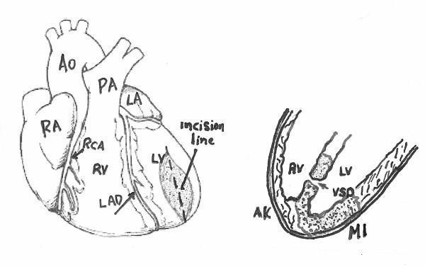
This medical illustration consists of two diagrams depicting cardiac anatomy and pathology associated with myocardial infarction and surgical intervention. The left panel shows an anterior view of the heart with major structures labeled: Right Atrium (RA), Right Ventricle (RV), Left Atrium (LA), Left Ventricle (LV), Aorta (Ao), and Pulmonary Artery (PA). The coronary vasculature is highlighted, specifically the Right Coronary Artery (RCA) and Left Anterior Descending (LAD) artery. An 'incision line' is indicated on the apex of the left ventricle over a shaded area representing infarcted tissue. The right panel is a cross-sectional diagram focusing on the ventricular chambers. It illustrates a Ventricular Septal Defect (VSD), which is a communication between the left and right ventricles. Also labeled are the Aortic Valve (AV), an area of Myocardial Infarction (MI) in the ventricular wall, and adjacent Akinetic (AK) tissue. The illustration serves to demonstrate the anatomical location for a ventriculotomy used to repair post-infarction ventricular septal rupture.
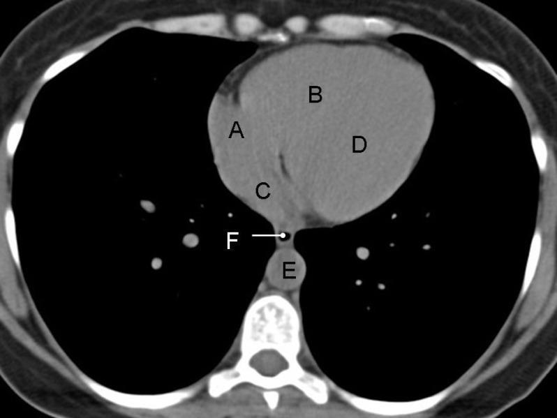
This diagnostic image is an axial non-contrast CT scan of the chest at the level of the heart. The visual highlights the anatomical relationships of cardiac and mediastinal structures labeled A through F. The right atrium (A) is positioned anteriorly and to the patient's right, while the right ventricle (B) occupies the most anterior central position. The left atrium (C) is located posteriorly relative to the right atrium, and the left ventricle (D) is situated posteriorly and to the left of the right ventricle. In the posterior mediastinum, the esophagus (F) is visible as a collapsed structure positioned between the left atrium and the descending thoracic aorta (E), which sits anterior and to the left of the vertebral column. Notably, the lack of intravenous contrast results in uniform soft-tissue attenuation across the cardiac chambers, demonstrating the clinical challenge of delineating the interventricular septum and endocardial borders on non-contrast imaging. This scan serves as an educational reference for normal cross-sectional anatomy and mediastinal spatial orientation.
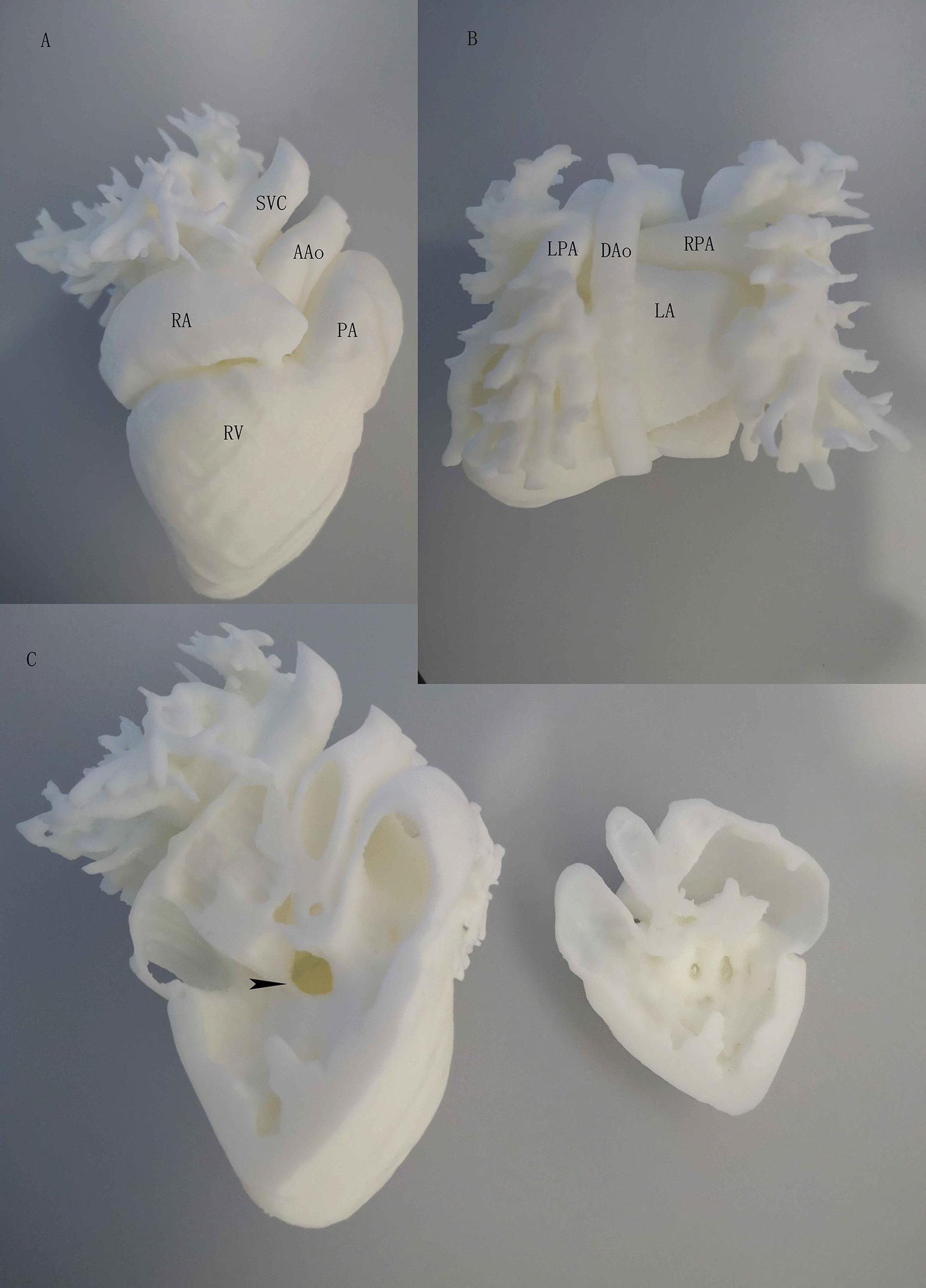
This composite educational image features a high-fidelity, white 3D-printed heart model used for clinical demonstration and surgical planning. Figure A (Front View): Highlights the anterior cardiac anatomy, including the right atrium (RA), right ventricle (RV), ascending aorta (AAo), superior vena cava (SVC), and pulmonary artery (PA). The spatial orientation shows the SVC entering the RA superiorly and the AAo originating from the base of the heart adjacent to the PA. Figure B (Back View): Provides a posterior perspective identifying the left atrium (LA), descending aorta (DAo), and the branching of the pulmonary arteries (LPA and RPA). Figure C (Inside View): Displays a coronal cross-section through the right ventricle, revealing the internal septal anatomy. An arrowhead points to a perimembranous ventricular septal defect (VSD), visualized as a distinct opening in the superior portion of the interventricular septum that allows communication between the ventricles. The model serves as a pedagogical tool for congenital heart disease education, specifically illustrating a large VSD and its relationship to major great vessels.
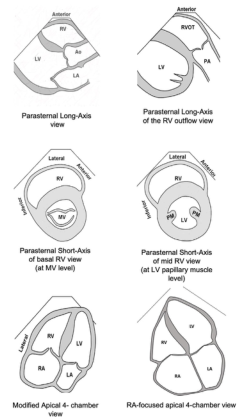
Summary : This figure presents six schematic diagrams of standard echocardiographic views used to visualize the heart chambers and valves, specifically focusing on the right ventricle (RV) and its relationship to other cardiac structures. illustration: # Views Presented : • Parasternal Long-Axis view: Shows RV, Ao (aorta), and LA (left atrium) in a longitudinal section. • Parasternal Long-Axis of the RV outflow view: Displays RVOT (right ventricular outflow tract), PA (pulmonary artery), and LV (left ventricle). • Parasternal Short-Axis of basal RV view (at MV level): Cross-sectional view at the mitral valve (MV) level, showing RV and MV. • Parasternal Short-Axis of mid RV view (at LV papillary muscle level): Cross-sectional view at the level of the LV papillary muscles, showing RV, LV, and papillary muscles (PM). • Modified Apical 4-chamber view: Displays RA (right atrium), RV, LA, and LV in a four-chamber perspective. • RA-focused apical 4-chamber view: Focuses on RA, RV, LA, and LV, emphasizing the right atrium. # Labels & Orientation : • Each diagram is labeled with anatomical structures (RV, LV, LA, RA, Ao, PA, MV, PM). • Orientation markers such as "Anterior," "Lateral," and "Septal" are provided for spatial reference. # Design Encodings : • Simple black-and-white line drawings. • Chamber walls and valves are outlined; no colour or shading. • Each view is titled below the corresponding diagram. # Analysis : • The figure systematically compares different echocardiographic views, highlighting how the right ventricle and associated structures appear in each orientation. • The progression from long-axis to short-axis and apical views demonstrates the versatility of echocardiography in assessing cardiac anatomy and function. • The inclusion of both standard and modified views allows for comprehensive visualization of the right heart.
heart external anatomy labeled anterior interventricular groove posterior atrioventricular groove coronary sulcus superior inferior vena cava pulmonary veins aorta
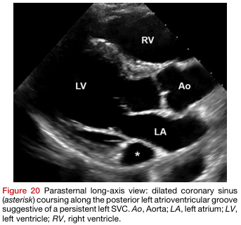
Summary : This figure is a parasternal long-axis echocardiographic view of the heart, highlighting a dilated coronary sinus (marked by an asterisk) in relation to the cardiac chambers and aorta, suggestive of a persistent left superior vena cava (SVC). photo: Scene Overview : • Main subject: Echocardiographic image of the heart in the parasternal long-axis view. • Key anatomical structures labeled: LV (left ventricle), RV (right ventricle), LA (left atrium), Ao (aorta), and a dilated coronary sinus (marked with an asterisk). • The coronary sinus is seen coursing along the posterior left atrioventricular groove. Technical Details : • Imaging modality: Echocardiography (ultrasound). • No scale bar or magnification indicated. • Labels are overlaid directly on the image for anatomical reference. Spatial Relationships : • LV (left ventricle) is positioned centrally and to the left. • RV (right ventricle) is superior and to the right. • LA (left atrium) is inferior and to the right of the LV. • Ao (aorta) is anterior to the LA and LV. • The asterisk marks the dilated coronary sinus, located posterior to the LA. Analysis : • The image demonstrates a dilated coronary sinus, which is an abnormal finding and may indicate the presence of a persistent left SVC. • The anatomical relationships between the cardiac chambers and great vessels are clearly visualized, aiding in the identification of the abnormal coronary sinus.
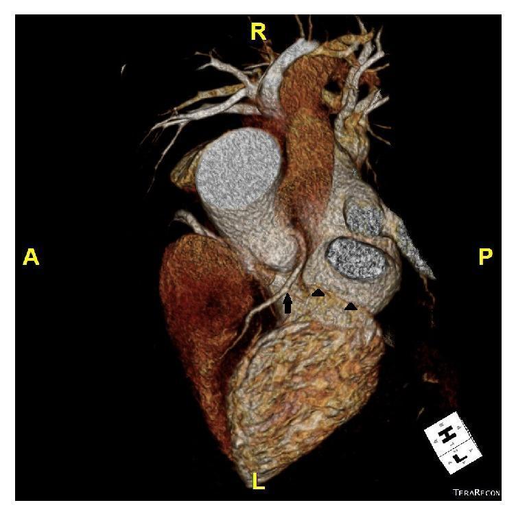
This diagnostic image is a three-dimensional volume-rendered computed tomography (CT) coronary angiogram of the human heart, presented from a superior (top) view. Anatomical orientation markers indicate Anterior (A), Posterior (P), Right (R), and Left (L) axes. The image highlights a rare congenital coronary artery anomaly: the isolated absence of the left circumflex artery (LCX). A single arrow points to the left anterior descending (LAD) artery, which originates and courses normally along the anterior interventricular groove toward the apex. Black arrowheads indicate the vacant atrioventricular groove where the LCX would typically reside. Other visible structures include the ascending aorta, positioned centrally and oriented toward the right, and the superior vena cava. This scan is educationally significant for demonstrating coronary anatomical variants that may mimic ischemic heart disease symptoms, such as exertional dyspnea, by altering typical myocardial perfusion patterns despite the absence of obstructive atherosclerotic lesions.
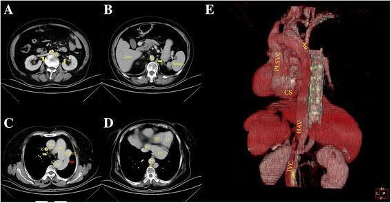
This composite figure contains axial contrast-enhanced CT scans (A-D) and a 3D reconstructive image (E) detailing complex congenital venous anomalies. The axial images show an interrupted left inferior vena cava (IVC) positioned posterolateral to the abdominal aorta, receiving drainage from bilateral renal veins. The IVC ascends and continues as an enlarged hemiazygos vein (HAV), which then progresses via the accessory hemiazygos vein into a persistent left superior vena cava (PLSVC). The PLSVC is shown draining into a significantly dilated coronary sinus (CS) within the left atrioventricular groove, which ultimately empties into the right atrium. Image C highlights a small azygos vein anterior to the vertebra crossing to the right superior vena cava (R-SVC), while image D demonstrates the massive coronary sinus. The 3D reconstruction (E) provides a comprehensive spatial overview of the anomalous pathway from the left IVC through the hemiazygos system and PLSVC to the heart, illustrating the anatomical relationship with the aorta and cardiac chambers.
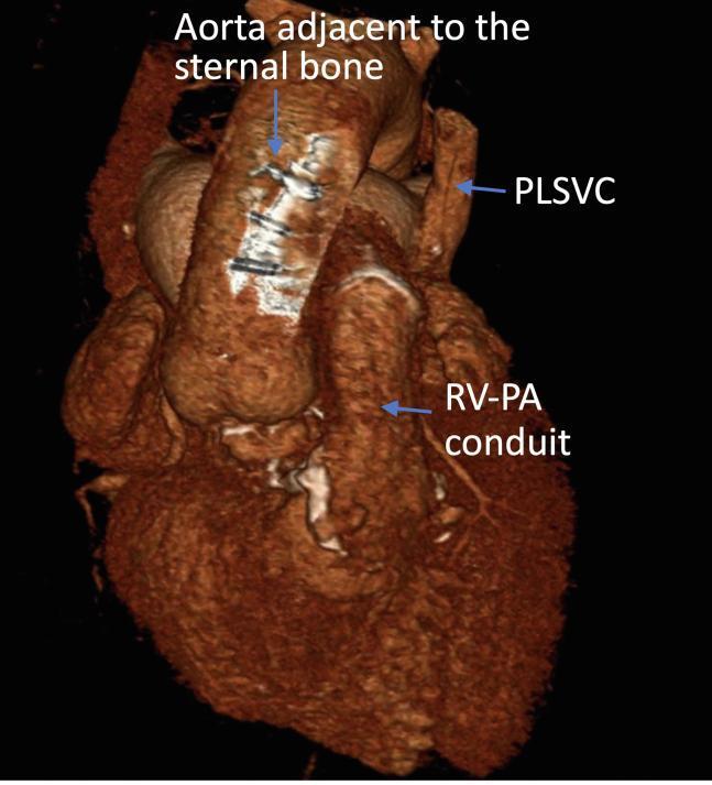
This diagnostic image shows a three-dimensional volume-rendered reconstruction of a computed tomography (CT) scan of the heart and great vessels, highlighting complex cardiovascular anatomy in a preoperative context. The reconstruction demonstrates the aorta's close proximity to the posterior surface of the sternal bone, a critical finding for planning redo sternotomies to avoid catastrophic vascular injury. Key vascular structures are labeled, including a persistent left superior vena cava (PLSVC) located on the anatomical left, and a right ventricle-to-pulmonary artery (RV-PA) conduit, which is visible as a tube-like prosthetic structure connecting the inferior heart chamber to the pulmonary circulation. The image illustrates post-surgical anatomy and congenital variations, specifically targeting advanced cardiothoracic surgical planning. Sternal wires or artifacts are visible on the anterior surface of the aorta where it is adjacent to the bone. This visual resource is used to educate on the spatial relationships in complex adult congenital heart disease and the utility of 3D CT modeling for surgical safety.
Detailed labeled anatomical diagram of the human heart showing: anterior view with right atrium (RA), right ventricle (RV), left atrium (LA), left ventricle (LV), superior vena cava (SVC), inferior vena cava (IVC), pulmonary trunk, aortic arch, left and right pulmonary arteries, pulmonary veins, anterior interventricular groove, atrioventricular (coronary) sulcus, posterior interventricular groove, coronary arteries, apex; also a posterior view showing the same structures from behind, all clearly labeled with arrows
Heart Anatomy - All Components, Chambers, Vessels & Grooves
Generated Labeled Diagram (Anterior + Posterior Views)
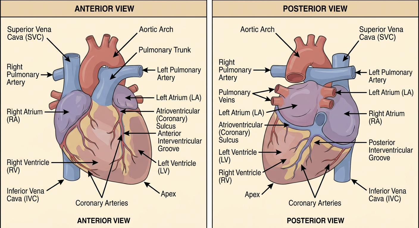
3D Heart Model - Anterior & Posterior Views
CT 3D Reconstruction - Superior View Showing Grooves
Key Structures Labeled
Chambers
| Chamber | Description |
|---|---|
| Right Atrium (RA) | Receives deoxygenated blood from SVC & IVC |
| Right Ventricle (RV) | Pumps blood to lungs via pulmonary trunk |
| Left Atrium (LA) | Receives oxygenated blood from 4 pulmonary veins |
| Left Ventricle (LV) | Pumps oxygenated blood to body via aorta |
Veins
- Superior Vena Cava (SVC) - drains upper body into RA
- Inferior Vena Cava (IVC) - drains lower body into RA
- Pulmonary veins (4 total: right superior, right inferior, left superior, left inferior) - drain into LA
- Coronary sinus - drains myocardial veins into RA
Arteries
- Ascending Aorta (AAo) / Aortic Arch - exits LV
- Pulmonary Trunk - exits RV, splits into left pulmonary artery (LPA) and right pulmonary artery (RPA)
- Left Anterior Descending (LAD) coronary artery
- Right Coronary Artery (RCA)
Grooves (Sulci)
| Groove | Location | Significance |
|---|---|---|
| Anterior interventricular groove | Anterior surface, between RV & LV | Contains LAD artery |
| Posterior interventricular groove | Posterior surface, between RV & LV | Contains posterior descending artery |
| Atrioventricular (coronary) sulcus | Encircles heart between atria & ventricles | Contains RCA and circumflex artery |
Also, give me the content of the groups. Salukas. Salukas. S-U-L-C-I.
cardiac sulci heart grooves labeled coronary sulcus anterior interventricular sulcus posterior interventricular sulcus diagram anatomy
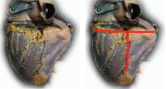
This clinical photograph shows a diaphragmatic (inferior) view of a human heart specimen. The image is presented in a side-by-side comparison format: the left panel displays the original gross specimen, while the right panel includes red annotations highlighting key anatomical landmarks. The cardiac surface exhibits a mottled reddish-brown myocardium with visible yellow epicardial adipose tissue concentrated along the sulci. The annotations demonstrate a 'T-shaped' intersection of major grooves: a horizontal red line identifies the coronary sulcus (atrioventricular groove), and a perpendicular vertical red line identifies the posterior interventricular sulcus. These landmarks delineate the boundaries between the atria and ventricles, and between the left and right ventricles, respectively. The educational focus is on the spatial orientation of cardiac surface anatomy and the identification of major coronary pathways as they appear from an inferior perspective.
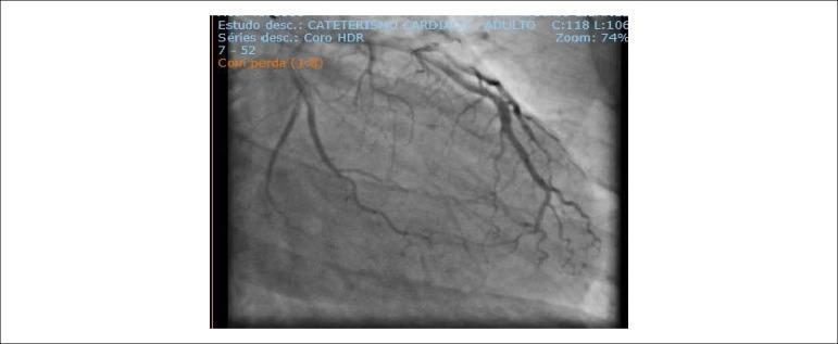
This diagnostic image is a coronary angiogram obtained during cardiac catheterization, showing the left coronary artery system in an adult patient. The primary focus is the left anterior descending artery (LAD), which displays a large caliber and significant longitudinal extension, reaching toward the apex and branching into the posterior interventricular sulcus. Also visible is the circumflex artery (LCx), which appears non-dominant and of relatively shorter extension, giving rise to an atrioventricular branch. The imaging specifically highlights the coronary anatomy and evaluates for the presence of collateral circulation; notably, the image demonstrates an absence of collateral flow from the left-sided circulation to the right coronary artery (RCA) territory. The vasculature is clearly delineated with radiopaque contrast, allowing for the assessment of vessel morphology, caliber, and the exclusion of obstructive coronary atherosclerosis in the visualized segments. This image serves as a clinical teaching tool for coronary anatomy, dominance patterns, and the evaluation of ischemic heart disease via invasive hemodynamic monitoring.
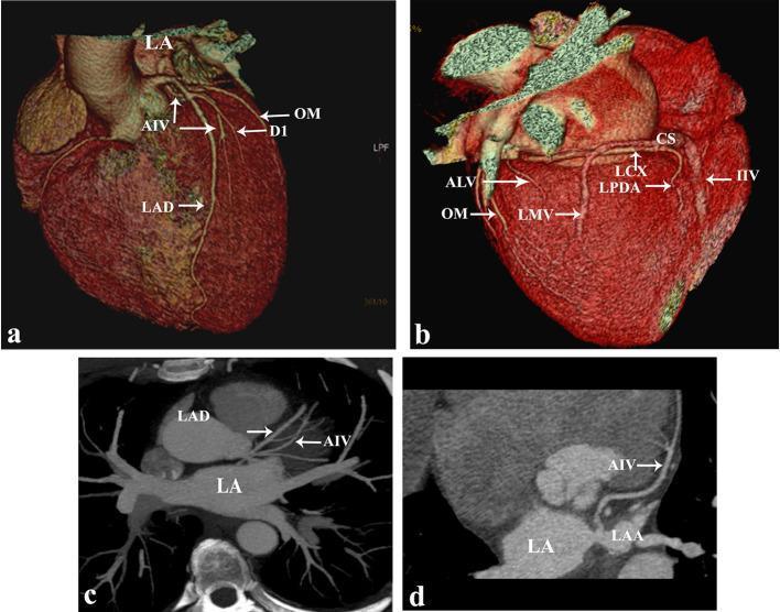
This set of diagnostic images from multidetector coronary CT (MDCT) illustrates the cardiac vasculature and a rare congenital anomaly. Panels (a) and (b) show 3D volume-rendered reconstructions of the heart. Panel (a) highlights the anterior surface where the anterior interventricular vein (AIV) and left anterior descending artery (LAD) course together in the interventricular sulcus. Notably, the AIV is seen passing deep to the first diagonal artery (D1). Panel (b) shows the posterior/inferior cardiac view including the coronary sinus (CS), left circumflex artery (LCx), and inferior interventricular vein (IIV). Panels (c) and (d) utilize oblique maximum intensity projection (MIP) and curved reformatted views to demonstrate the anomalous drainage of the AIV directly into the left atrium (LA) rather than the coronary sinus. Key structures labeled include the left atrial appendage (LAA), obtuse marginal artery (OM), and left marginal vein (LMV). This educational material demonstrates the utility of advanced cardiac CT imaging in identifying venous anomalies and defining complex spatial relationships between coronary arteries and veins for clinical diagnosis or surgical planning.
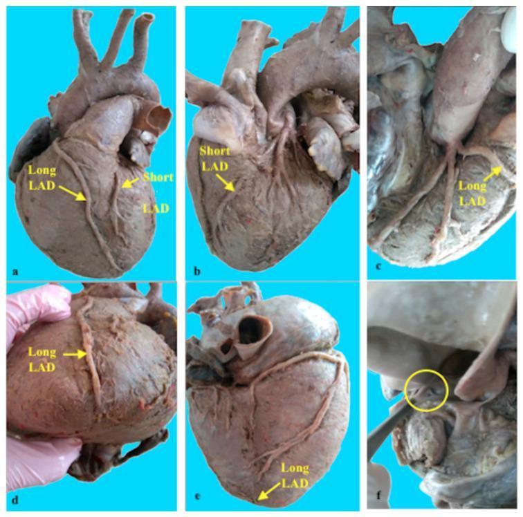
This composite of six clinical photographs (labeled a-f) documents a rare anatomical variant known as a Type XIV double anterior interventricular artery (left anterior descending artery, or LAD). The specimen images highlight the coexistence of a 'Short LAD' and a 'Long LAD' on a human heart. Panels (a) and (b) show the 'Short LAD' originating from the left coronary artery, characterized by a brief course along the anterior interventricular groove and containing a visible muscular bridge in its middle segment. Panels (a), (d), and (e) illustrate the 'Long LAD' extending significantly toward and exceeding the cardiac apex to reach the distal posterior interventricular sulcus. Panels (c) and (f) provide detailed views of the separate aortic origin of the 'Long LAD' from the right coronary sinus. This visual set demonstrates complex coronary artery variations and the presence of myocardial bridging, which are critical concepts in cardiovascular anatomy, diagnostic radiology, and cardiothoracic surgery planning.
Cardiac Sulci (Grooves) - Complete Content
Source: Gray's Anatomy for Students, Fig. 3.70
1. Coronary Sulcus (Atrioventricular Sulcus)
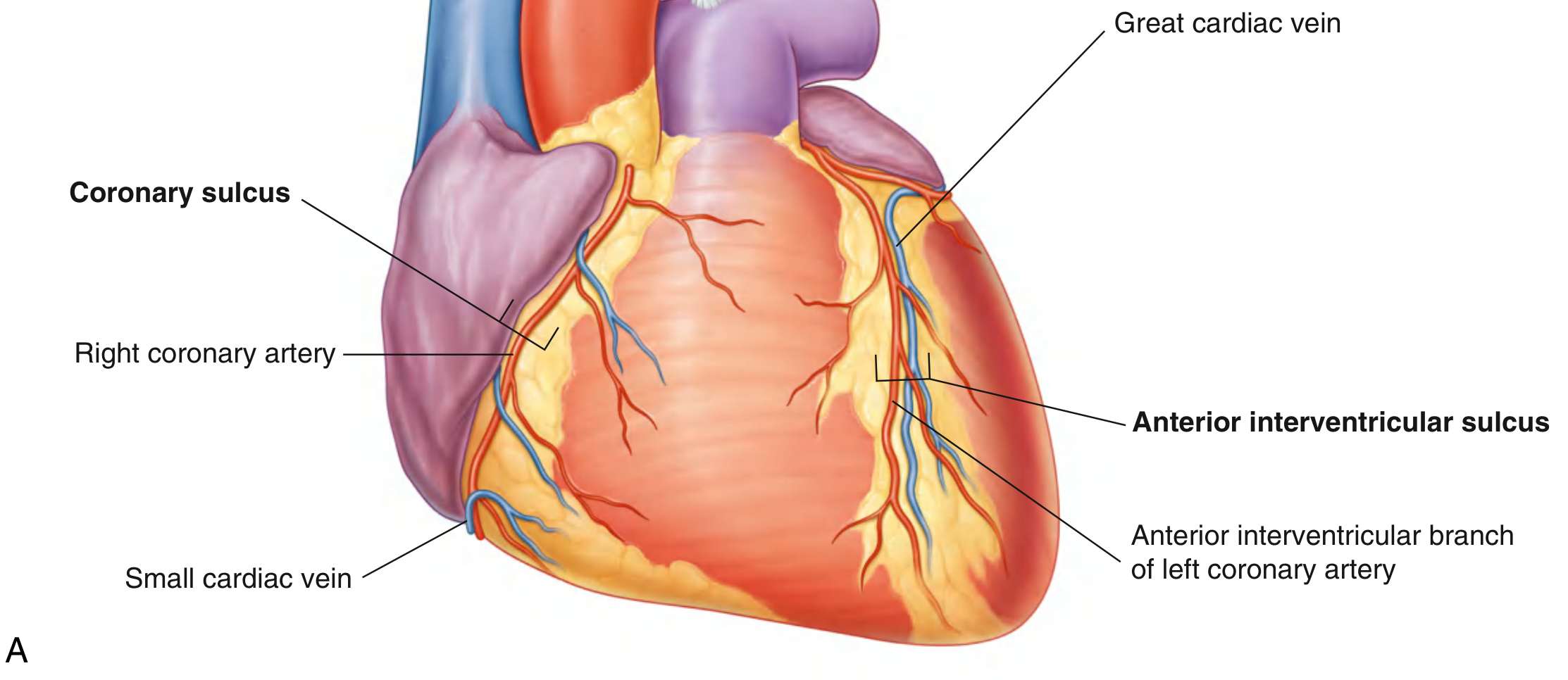
- Location: Circles the entire heart horizontally, separating the atria (above) from the ventricles (below)
- Contents:
- Right coronary artery (RCA)
- Small cardiac vein
- Coronary sinus
- Circumflex branch of the left coronary artery
2. Anterior Interventricular Sulcus
- Location: On the anterior (sternocostal) surface of the heart, running diagonally from base to apex between the right and left ventricles
- Contents:
- Anterior interventricular artery (= Left Anterior Descending artery, LAD)
- Great cardiac vein
3. Posterior Interventricular Sulcus
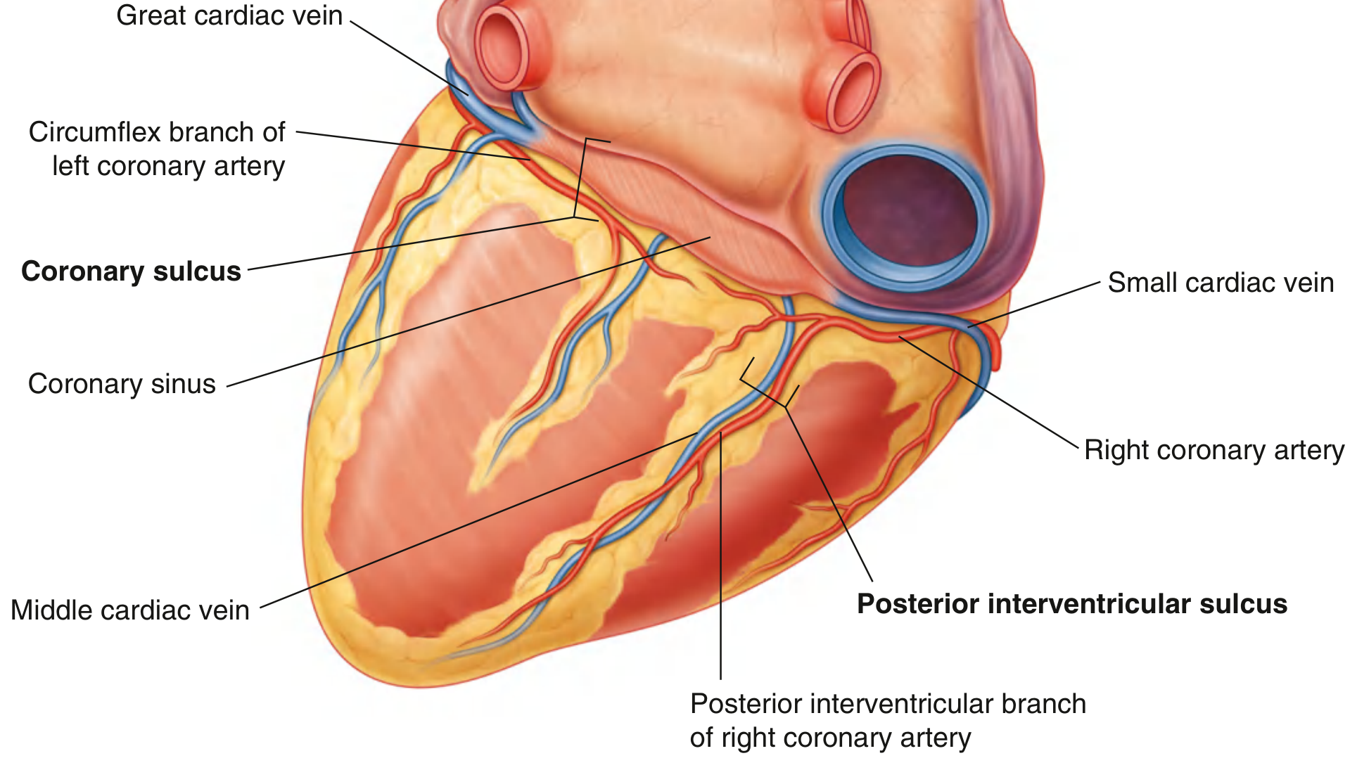
- Location: On the diaphragmatic (inferior/posterior) surface of the heart, between the right and left ventricles
- Contents:
- Posterior interventricular artery (= Posterior Descending Artery, PDA - branch of RCA in most people)
- Middle cardiac vein
Key Relationship Between All Three Sulci
Summary Table
| Sulcus | Surface | Separates | Artery Inside | Vein Inside |
|---|---|---|---|---|
| Coronary sulcus | All surfaces (encircles heart) | Atria from ventricles | RCA + circumflex branch | Small cardiac vein + coronary sinus |
| Anterior interventricular sulcus | Anterior (sternocostal) | RV from LV (anteriorly) | LAD (anterior interventricular a.) | Great cardiac vein |
| Posterior interventricular sulcus | Inferior (diaphragmatic) | RV from LV (posteriorly) | PDA (posterior interventricular a.) | Middle cardiac vein |