
Extraocular muscles with their functions attachment and squint
extraocular muscles anatomy diagram eye movements
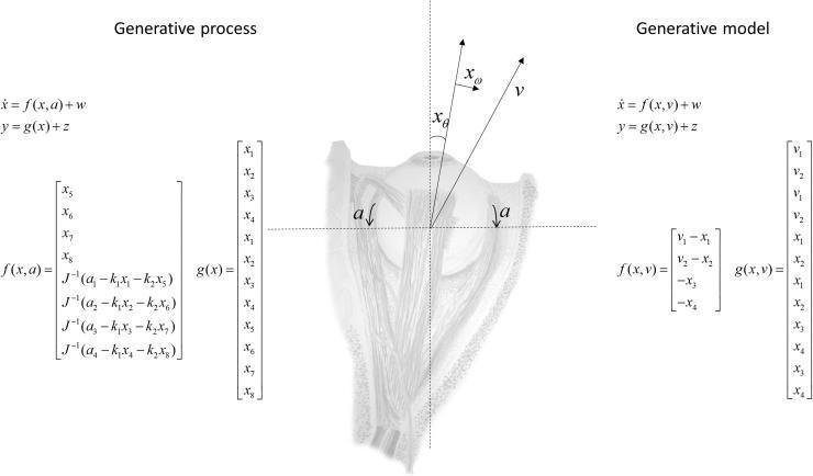
This medical diagram presents a comparison between the biological 'Generative Process' (left) and a computational 'Generative Model' (right) for eye movement dynamics. At the center is an anatomical illustration of a human eyeball with its extraocular muscles, annotated with vectors for angular position (xθ), angular velocity (xω), and target fixation (v). Arrows labeled 'a' represent muscle torque action. The 'Generative Process' section on the left utilizes a high-dimensional state space (x1–x8) representing independent movement of both eyes, incorporating physical constants like the moment of inertia (J), spring constants (k1), and viscosity (k2) within matrices f(x,a) and g(x). In contrast, the 'Generative Model' on the right simplifies these dynamics for predictive coding, assuming conjugate eye movements (x1–x4) where horizontal and vertical positions are shared. The diagram illustrates how internal generative models in the brain approximate complex physical oculomotor processes to minimize prediction errors during saccades and smooth pursuit.
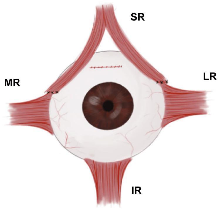
This medical illustration depicts a surgical procedure on the extraocular muscles of the left eye, identified as the Sesma-AlGhazal procedure. The anatomical diagram shows the eyeball with four rectus muscles: Superior Rectus (SR), Medial Rectus (MR), Lateral Rectus (LR), and Inferior Rectus (IR). The SR muscle is demonstrated as longitudinally split into two distinct halves. The medial half of the SR has been transposed and sutured anterior to the original insertion of the MR. Simultaneously, the lateral half of the SR has been transposed and sutured superior to the insertion point of the LR. Black surgical sutures are visible at both new insertion points and at the original superior scleral site where the SR was detached. This muscle transpositioning technique is used in ophthalmology to correct specific forms of strabismus, such as hypotropia, by redistributing the mechanical forces of the SR to assist adjacent muscles. The diagram serves as an educational tool for ophthalmologists and medical students to understand ocular motility surgery and muscle transposition geometry.
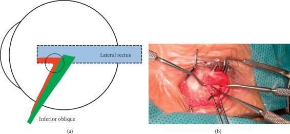
This composite educational material consists of an anatomical diagram and a clinical photograph detailing Type-beta inferior oblique muscle enlargement (IO-E). Part (a) is a schematic illustration of the lateral aspect of the eye globe. It depicts the lateral rectus muscle (blue) and the inferior oblique muscle bifurcating into two bundles: a posterior bundle (green) that inserts into the conventional scleral position, and an anterior bundle (red) that loosely connects at the conventional insertion (purple circle) before coursing anteriorly beneath the lateral rectus to fuse with its insertion point. Part (b) is an intraoperative clinical photograph providing a surgical view of the ocular surface during strabismus surgery. The white sclera is exposed, and various surgical instruments, including muscle hooks, forceps, and a lid speculum, are used to manipulate the extraocular tissues and muscles for visualization of anomalous attachments. This content is intended for ophthalmic specialty training, focusing on surgical anatomy and the diagnosis of extraocular muscle variations related to vertical strabismus and V-pattern exotropia.
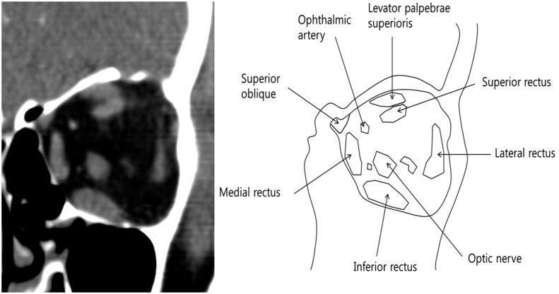
This composite educational graphic features a contrast-enhanced computerized tomography (CT) scan and a corresponding anatomical schematic of the left orbit in the coronal plane. The CT image displays the soft tissue window, highlighting the retrobulbar space and extraocular muscles (EOM) within the orbital fat. The accompanying diagram provides labeled identification of the orbital contents, including the superior rectus, inferior rectus, medial rectus, and lateral rectus muscles. Additionally, the schematic delineates the superior oblique, levator palpebrae superioris, ophthalmic artery, and the central optic nerve. The visual focus is on the cross-sectional morphology of the EOMs, particularly demonstrating a larger cross-sectional area of the inferior rectus compared to the superior rectus. This comparison is relevant for assessing Thyroid Eye Disease (TED) or other orbital pathologies involving muscle hypertrophy. The material is designed for intermediate to advanced medical education, specifically within ophthalmology and radiology, to teach orbital anatomy and the diagnostic interpretation of CT scans for muscle-sparing or involvement patterns.
strabismus squint esotropia exotropia types clinical
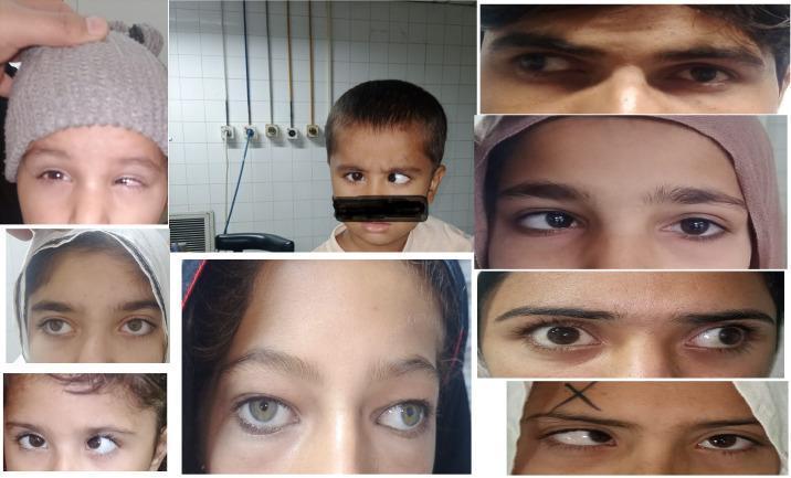
A collage of clinical photographs showcasing various manifestations of strabismus (squint) in pediatric and adult patients. The images demonstrate different types of ocular misalignment, including esotropia (inward deviation of one eye) and exotropia (outward deviation of one eye) relative to the fixating eye. Several frames highlight the asymmetry in pupillary alignment and the visible corneal light reflex displacement, which are key diagnostic signs. The collection illustrates clinical variations in the degree of deviation, ranging from subtle misalignment to more pronounced, large-angle strabismus. These visual findings are frequently associated with amblyopia (lazy eye), where the brain favors the visual input from the correctly aligned eye. The clinical relevance of this visual resource is in ophthalmology and optometry education, specifically for identifying sensory and motor ocular abnormalities and understanding the visual presentation of binocular vision disorders.
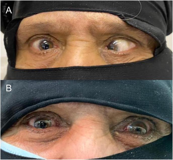
This clinical comparison photograph illustrates the preoperative and postoperative results of surgical correction for a complex strabismus case, specifically high myopic esotropia (Heavy Eye Syndrome). Image A (top) displays the preoperative state in primary gaze, showing severe large-angle esotropia (inward deviation) of both eyes. The right eye exhibits a nasal shift, while the left eye shows an extreme nasal deviation with significant scleral exposure temporally, consistent with a measured angle of >90 prism diopters. Image B (bottom) shows the patient four weeks post-surgery following bilateral loop myopexy (Yokoyama procedure) and medial rectus recession. The alignment is markedly improved; the large-angle esotropia is resolved, replaced by a mild, clinically acceptable exotropia (outward deviation) in the primary position. The clinical features demonstrate the successful repositioning of the globe and extraocular muscle paths (Superior Rectus and Lateral Rectus) to restore central alignment in a patient with a history of high myopia and prior retinal detachment surgery.
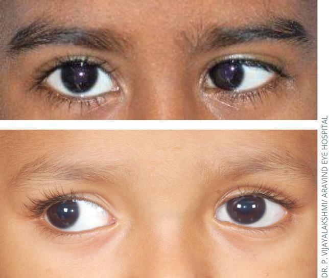
This comparison clinical photograph illustrates two common forms of strabismus (ocular misalignment) in pediatric patients, specifically focusing on horizontal deviations and the Hirschberg test (corneal light reflex). The top panel displays left esotropia, where the left eye is deviated medially (inward) relative to the fixating right eye; consequently, the corneal light reflex on the left eye is displaced temporally from the pupillary center. The bottom panel displays right exotropia, characterized by the lateral (outward) deviation of the right eye relative to the fixating left eye; here, the corneal light reflex on the right eye is displaced nasally. These images serve as an educational tool for ophthalmology and pediatrics to demonstrate the clinical manifestation of manifest strabismus (tropia) and the use of light reflex symmetry to identify ocular misalignment. The content is suitable for medical students and residents learning basic ophthalmic examination techniques and the diagnosis of binocular vision disorders.
Extraocular Muscles (EOMs): Anatomy, Functions, Attachments & Squint
Anatomy Overview
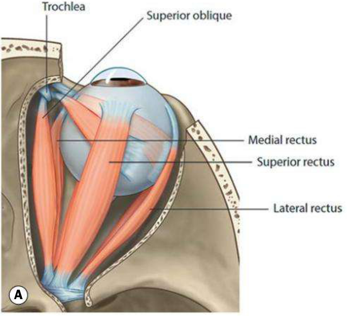
The Spiral of Tillaux
| Muscle | Distance from Limbus |
|---|---|
| Medial rectus | 5.5 mm (closest) |
| Inferior rectus | 6.5 mm |
| Lateral rectus | 6.9 mm |
| Superior rectus | 7.7 mm (furthest) |
Individual Muscles: Origin, Insertion, Nerve Supply & Actions
1. Medial Rectus (MR)
| Feature | Detail |
|---|---|
| Origin | Annulus of Zinn (medial part) |
| Insertion | 5.5 mm behind nasal limbus |
| Nerve | CN III (Oculomotor) - inferior division |
| Primary action | Adduction |
| Subsidiary actions | None (purely horizontal in primary position) |
2. Lateral Rectus (LR)
| Feature | Detail |
|---|---|
| Origin | Annulus of Zinn (lateral part) |
| Insertion | 6.9 mm behind temporal limbus |
| Nerve | CN VI (Abducens) |
| Primary action | Abduction |
| Subsidiary actions | None (purely horizontal in primary position) |
3. Superior Rectus (SR)
| Feature | Detail |
|---|---|
| Origin | Annulus of Zinn (upper part) |
| Insertion | 7.7 mm behind superior limbus |
| Nerve | CN III (Oculomotor) - superior division |
| Primary action | Elevation |
| Secondary actions | Adduction + Intorsion |
| Testing position | Abduct 23° (visual and orbital axes coincide - pure elevation) |
4. Inferior Rectus (IR)
| Feature | Detail |
|---|---|
| Origin | Annulus of Zinn (lower part) |
| Insertion | 6.5 mm behind inferior limbus |
| Nerve | CN III (Oculomotor) - inferior division |
| Primary action | Depression |
| Secondary actions | Adduction + Extorsion |
| Testing position | Abduct 23° (pure depression) |
5. Superior Oblique (SO)
| Feature | Detail |
|---|---|
| Origin | Superomedial to optic foramen |
| Course | Passes forward through the trochlea (pulley at superomedial orbital wall), then reflected backwards and laterally |
| Insertion | Posterior upper temporal quadrant of globe (behind equator, at 51° to visual axis) |
| Nerve | CN IV (Trochlear) - supplies contralateral SO |
| Primary action | Intorsion |
| Secondary actions | Depression + Abduction |
| Testing position | Adduct eye - SO is the best depressor in adduction |
6. Inferior Oblique (IO)
| Feature | Detail |
|---|---|
| Origin | Anterolateral floor of orbit (lateral to lacrimal fossa) - unique: does NOT arise from Annulus of Zinn |
| Insertion | Posterior inferior temporal quadrant of globe (behind equator) |
| Nerve | CN III (Oculomotor) - inferior division |
| Primary action | Extorsion |
| Secondary actions | Elevation + Abduction |
| Testing position | Adduct eye - IO is the best elevator in adduction |
Memory Aid: Actions
| Muscle | 1° | 2° | 3° |
|---|---|---|---|
| Superior Rectus | Elevation | Adduction | Intorsion |
| Inferior Rectus | Depression | Adduction | Extorsion |
| Superior Oblique | Intorsion | Depression | Abduction |
| Inferior Oblique | Extorsion | Elevation | Abduction |
Mnemonic for obliques: "SO depresses the adducted eye; IO elevates the adducted eye"
Nerve Supply Summary
| Nerve | Cranial Nerve | Muscles Supplied |
|---|---|---|
| Oculomotor (CN III) | III | MR, SR, IR, IO + levator palpebrae superioris |
| Trochlear (CN IV) | IV | SO only (contralateral) |
| Abducens (CN VI) | VI | LR only |
Mnemonic: LR6SO4 - Lateral Rectus = CN6, Superior Oblique = CN4, all others = CN3
Laws of Ocular Motility
- Sherrington's Law of Reciprocal Innervation: When an agonist muscle receives increased innervation, its antagonist in the same eye receives decreased innervation simultaneously (e.g., when MR contracts, LR relaxes).
- Hering's Law of Equal Innervation: During conjugate eye movements, equal and simultaneous innervation flows to the yoke muscles (one in each eye).
- Yoke muscles are contralateral synergists that produce conjugate movements - e.g., the yoke muscle of the left superior oblique is the right inferior rectus.
Diagnostic Positions of Gaze (Cardinal Positions)
| Direction | Yoke Pair (Right eye / Left eye) |
|---|---|
| Dextroversion (right) | Right LR + Left MR |
| Laevoversion (left) | Left LR + Right MR |
| Dextroelevation (up-right) | Right SR + Left IO |
| Laevoelevation (up-left) | Left SR + Right IO |
| Dextrodepression (down-right) | Right IR + Left SO |
| Laevodepression (down-left) | Left IR + Right SO |
Squint (Strabismus)
Classification
| Type | Deviation |
|---|---|
| Esotropia (convergent squint) | Eye turns inward (nasally) |
| Exotropia (divergent squint) | Eye turns outward (temporally) |
| Hypertropia | Eye turns upward |
| Hypotropia | Eye turns downward |
| Cyclotropia | Torsional deviation |
| Type | Description |
|---|---|
| Comitant (concomitant) | Angle of deviation is the same in all positions of gaze; no muscle palsy; common in children |
| Incomitant (paralytic) | Angle varies with direction of gaze; due to muscle palsy or restriction |
Squint Due to Individual Muscle Palsy
| Nerve Palsy | Muscle Affected | Squint/Deviation | Clinical Features |
|---|---|---|---|
| CN III palsy | MR, SR, IR, IO | Exotropia + hypotropia (eye down and out) | Ptosis, dilated fixed pupil (complete III palsy) |
| CN IV palsy | Superior Oblique | Hypertropia (eye elevated) | Vertical diplopia, head tilt to opposite side (compensatory) |
| CN VI palsy | Lateral Rectus | Esotropia (eye turned in) | Inability to abduct; diplopia on ipsilateral gaze |
AC/A Ratio and Strabismus
Pseudo-Squint
- A large positive angle kappa causes the corneal reflex to appear displaced temporally, mimicking exotropia (pseudo-exotropia)
- Commonly seen in premature infants with temporal foveal displacement (e.g., from retinopathy of prematurity)
Key Points Summary
- All recti arise from the Annulus of Zinn; the inferior oblique is the only EOM that does NOT.
- Only LR (CN VI) and SO (CN IV) have their own dedicated nerves; all other EOMs are supplied by CN III.
- The trochlea acts as a pulley, redirecting the SO tendon - making the functional origin of SO the trochlea, not its anatomical origin.
- Vertical recti and obliques have 3 actions each; horizontal recti have only 1 action in primary position.
- Obliques are inserted behind the equator (51° to visual axis); recti are inserted in front of the equator (23° to visual axis for vertical recti).
- In CN IV palsy, patients tilt the head toward the unaffected side to minimize diplopia - this is a classic clinical sign.
- Kanski's Clinical Ophthalmology: A Systematic Approach, 10th ed., pp. 723-727
- Neuroanatomy through Clinical Cases, 3rd ed., Ch. 12
- Adams and Victor's Principles of Neurology, 12th ed.
Squint findings on retuna
anomalous retinal correspondence suppression amblyopia strabismus retina diagram
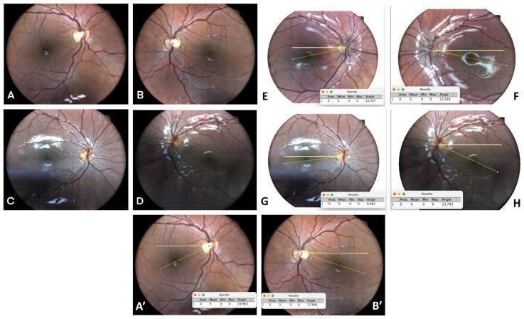
A multi-panel compilation of diagnostic fundus photographs illustrating various forms of strabismus and ocular torsion. Images A-D provide pre- and post-operative comparisons of the retina in cases of horizontal strabismus, showing the optic disc, macula, and retinal vasculature. Panels E-H and A'-B' utilize digital analysis software (ImageJ) to quantify ocular torsion, featuring yellow angular overlays that measure the disc-fovea angle. These quantitative frames demonstrate esotropia and exotropia with associated torsion, as well as severe torsion in a patient with craniosynostosis-related orbital abnormalities. The images highlight the clinical relationship between retinal landmark displacement (fundus torsion) and binocular vision disorders like strabismus and torsional amblyopia. Key features include the orientation of the vascular arcades and the relative vertical position of the fovea to the optic disc, which serves as a clinical indicator for diagnosing and measuring cyclodeviation in pediatric ophthalmology.
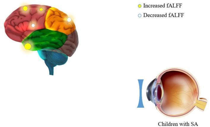
This composite educational graphic illustrates neurobiological and anatomical associations in children with strabismus amblyopia (SA). The upper-left portion features a lateral-view anatomical diagram of the human brain, color-coded by lobes: red (frontal), orange (parietal), and green (temporal). It overlays metabolic activity markers representing the fractional Amplitude of Low-Frequency Fluctuations (fALFF). Yellow circles indicate areas of increased fALFF (e.g., precentral gyrus, inferior parietal lobule), while white circles represent areas of decreased fALFF (e.g., superior frontal gyrus, temporal pole). The lower-right portion shows a sagittal cross-section of the human eye, detailing the cornea, iris, crystalline lens, and retina, with an external biconcave lens placed in front. This configuration demonstrates the clinical relationship between ocular structural correction and corresponding functional brain activity changes in pediatric patients with strabismus.
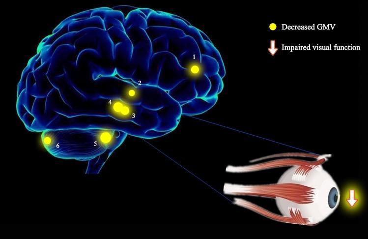
This medical illustration combines a three-dimensional brain rendering and an anatomical ocular diagram to demonstrate the pathophysiology of strabismus with amblyopia (SA). The brain model highlights six specific regions with decreased gray matter volume (GMV), indicated by numbered yellow spots: (1) left anterior cingulate, (2) right superior temporal gyrus, (3) right parahippocampal gyrus, (4) left parahippocampal gyrus, (5) right anterior lobe of the cerebellum, and (6) right posterior lobe of the cerebellum. The size of these spots represents the degree of quantitative change in GMV. A detailed illustration of the human eye, including extraocular muscles, is connected to the parahippocampal regions (3 and 4) via blue lines, suggesting a functional link. A downward-pointing arrow next to the eye signifies 'impaired visual function.' This visual summary illustrates research findings where significant GMV reduction in these specific cortical and cerebellar areas correlates with the visual and oculomotor deficits characteristic of patients with SA compared to healthy controls.
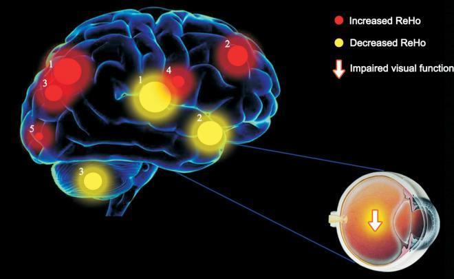
This medical illustration combines a 3D brain model with functional neuroimaging data to demonstrate the pathophysiology of strabismus amblyopia (SA). The diagram highlights changes in Regional Homogeneity (ReHo) values within the brain, representing local neural synchrony. Red circular markers signify increased ReHo, localized to the right lingual gyrus (BA 18), right superior frontal medial area (BA 8), and bilateral parietal regions (superior BA 7 and inferior BA 40). Yellow circular markers denote decreased ReHo, situated in the left putamen, left superior frontal gyrus (BA 13), and right cerebellum. The size of the markers indicates the degree of quantitative change. Accompanying the brain model is a cross-sectional diagram of a human eye with a downward-pointing arrow, symbolizing impaired visual function. The integration of these elements illustrates the correlation between peripheral ocular dysfunction and central nervous system reorganization, specifically emphasizing how strabismus impacts visual processing pathways and cortical synchronization.
fundus torsion disc fovea angle strabismus cyclotropia
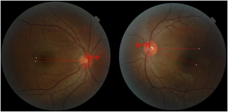
This diagnostic image consists of two side-by-side digital fundus photographs demonstrating the objective measurement of ocular torsion using the disc-foveal angle (DFA). The photographs show the posterior pole of the right (OD) and left (OS) eyes, highlighting the anatomical relationship between the optic disc and the fovea. In each frame, red annotation lines are superimposed: one horizontal line originating from the geometric center of the optic disc and a second line connecting the disc center to the fovea. In the right eye, the DFA is measured at -3.76°, indicating incyclotorsion as the fovea is positioned slightly above the horizontal plane of the optic disc. In the left eye, the DFA is 19.15°, signifying excyclotorsion with the fovea located significantly below the horizontal plane. This visual is used in ophthalmology to quantitatively assess cyclotropia, often related to superior oblique muscle palsy or other strabismus conditions, and to evaluate postoperative outcomes after muscle surgery.
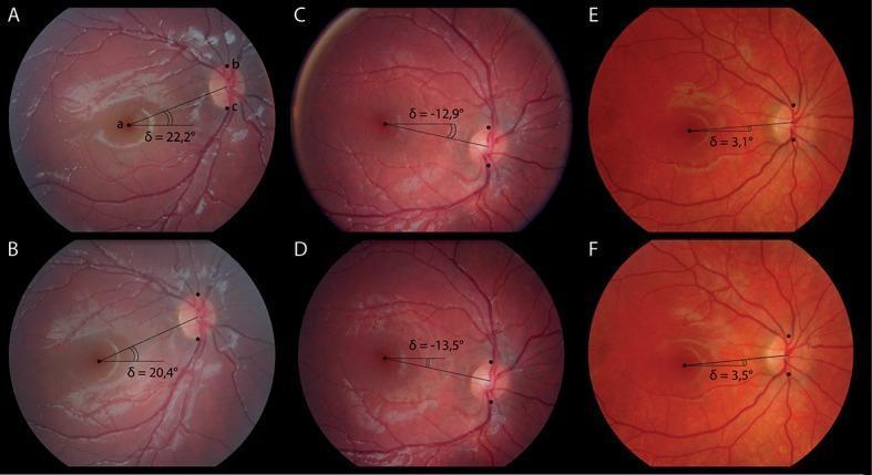
A series of six fundus photographs (A-F) demonstrating the measurement of the disc-foveal angle (δ) in various clinical scenarios, including V-pattern strabismus, healthy eyes, and A-pattern strabismus. Each image displays the retinal vasculature, optic disc, and fovea. Overlay lines and annotations show the geometric relationship between the center of the fovea and the optic nerve head relative to a horizontal reference line. Images A and B show a positive disc-foveal angle of approximately 20-22°, indicating significant excyclotorsion common in V-pattern strabismus. Images C and D display a negative angle (approximately -13°), representing incyclotorsion where the fovea is positioned higher than the optic disc. Images E and F show a near-neutral positive angle (approximately 3°), suggesting minor excyclotorsion. These images illustrate the use of fundus photography to objectively quantify ocular torsion, which is critical in diagnosing and managing cyclovertical strabismus and motility disorders.
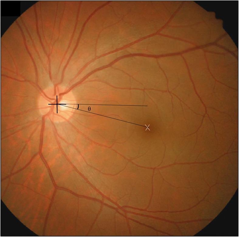
This clinical photograph is a fundus image of a human retina, demonstrating the disc-foveal method for assessing ocular torsion. The image shows a healthy reddish-orange retinal background with the optic disc positioned on the left and retinal blood vessels radiating outward in a normal branching pattern. A crosshair is centered on the optic disc, and a white 'X' marks the location of the fovea centralis within the macula. A geometric overlay illustrates the disc-foveal angle, labeled with the Greek letter 'θ' (theta). This angle is defined by a horizontal reference line extending from the center of the optic disc and a second line connecting the center of the optic disc to the fovea. This measurement is clinically significant in ophthalmology for quantifying excyclotorsion or incyclotorsion, particularly in patients with superior oblique muscle palsy or other forms of paralytic strabismus. The image serves as an educational tool for diagnostic imaging and surgical planning in strabismus management.
Retinal Findings in Squint (Strabismus)
1. The Two Core Problems Created by Squint
Confusion
Pathological Diplopia
- In esotropia: diplopia is homonymous (uncrossed) - the image from the deviated (nasal) eye projects temporally
- In exotropia: diplopia is heteronymous (crossed) - the image from the deviated (temporal) eye projects nasally
2. Sensory Retinal Adaptations to Squint
A. Suppression
| Type | Mechanism | Retinal Area |
|---|---|---|
| Central suppression | Image from the fovea of the deviating eye is inhibited | Suppresses central/macular area → avoids confusion |
| Peripheral suppression | Image from the peripheral retina of the deviating eye is inhibited | Eradicates diplopia |
- Monocular suppression: The dominant eye always predominates; the deviating eye is constantly suppressed → leads to amblyopia
- Alternating suppression: Switches from one eye to the other → amblyopia less likely to develop
- Facultative: Only when eyes are misaligned (e.g., intermittent exotropia, Duane syndrome)
- Obligatory: Present at all times regardless of alignment
B. Anomalous (Abnormal) Retinal Correspondence (ARC)
- Normally, the fovea of the right eye "corresponds" with the fovea of the left eye (Normal Retinal Correspondence - NRC)
- In ARC, the fovea of the fixating eye is paired with a non-foveal (eccentric) point in the deviated eye
- The brain reorganizes so that these two non-corresponding retinal points are treated as if they are "corresponding"
| Feature | Detail |
|---|---|
| Type of adaptation | Positive sensory adaptation (binocular vision maintained, unlike suppression) |
| Quality of BSV | Never as good as normal bifoveal binocular single vision (BSV) |
| Most common association | Small-angle esotropia (microtropia) |
| Less common in | Accommodative esotropia (due to variability of deviation) |
| Degree | Varies from harmonious ARC (anomalous angle = objective angle) to unharmonious ARC |
- The fovea of the fixating eye acquires an anomalous common visual direction with an extrafoveal locus in the deviating eye
- This extrafoveal locus becomes the "pseudo-fovea" and corresponds with the dominant fovea
3. Amblyopia (Lazy Eye) - The Critical Retinal Consequence
| Type | Mechanism |
|---|---|
| Strabismic amblyopia | Continued monocular suppression of the deviating eye → reduced cortical response to that eye |
| Anisometropic amblyopia | Difference in refractive error between eyes; frequently associated with microstrabismus |
| Stimulus deprivation amblyopia | Media opacity (cataract, ptosis) blocking image formation |
| Bilateral ametropic | High symmetrical hypermetropia |
| Meridional amblyopia | Uncorrected astigmatism causing meridional blur |
- 7-8 years in strabismic amblyopia
- Into teens for anisometropic amblyopia with good binocular function
4. Fundus Torsion in Squint (Cyclotropia)
- Normal DFA: approximately -3° to +5° (fovea slightly below the disc center)
- Excyclotorsion (extorsion): Fovea displaced below disc → increased positive DFA (e.g., +19°) - seen in inferior oblique overaction
- Incyclotorsion (intorsion): Fovea displaced above disc → negative DFA (e.g., -13°) - seen in superior oblique overaction
- Superior oblique palsy (CN IV palsy) → excyclotorsion of the affected eye
- V-pattern strabismus → increased positive DFA
- A-pattern strabismus → negative DFA
5. Normal Binocular Single Vision (BSV) - For Context
- Sensory fusion - cortical integration of two similar images
- Motor fusion - maintenance of alignment driven by retinal image disparity
- Stereopsis - depth perception from horizontally disparate retinal images within Panum's fusional space
Summary Table: Retinal Findings in Squint
| Finding | Location | When Occurs | Consequence |
|---|---|---|---|
| Foveal suppression | Central retina of deviating eye | Manifest squint (any angle) | Avoids confusion |
| Peripheral suppression | Peripheral retina of deviating eye | Manifest squint | Eliminates diplopia |
| ARC | Extrafoveal point in deviating eye | Small-angle squint (microtropia) | Anomalous BSV |
| Eccentric fixation | Non-foveal fixation point | Deep/longstanding amblyopia | Reduced VA |
| Fundus torsion (abnormal DFA) | Optic disc - fovea relationship | Cyclodeviation, CN IV palsy | Cyclotropia on fundoscopy |
| Amblyopia | Entire central visual pathway | Chronic monocular suppression in childhood | Permanent VA reduction if untreated |
- Kanski's Clinical Ophthalmology: A Systematic Approach, 10th Ed., pp. 728-733