
Diagram of coockup wrist splint
cock-up wrist splint diagram anatomy
Cock-Up Wrist Splint - Orthotic Pattern & Anatomy
Diagram 1 - Components of the Splint (Palmar View)
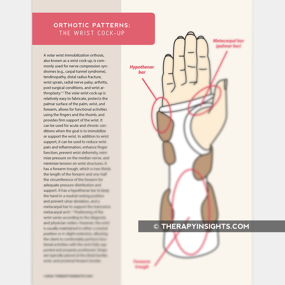
- Metacarpal bar (palmar bar) - supports the transverse metacarpal arch
- Hypothenar bar - keeps the hand in a neutral resting position and prevents ulnar deviation
- Forearm trough - extends 2/3 the length of the forearm, covering 1/2 the circumference
Diagram 2 - Fabrication Pattern with Anatomical Landmarks
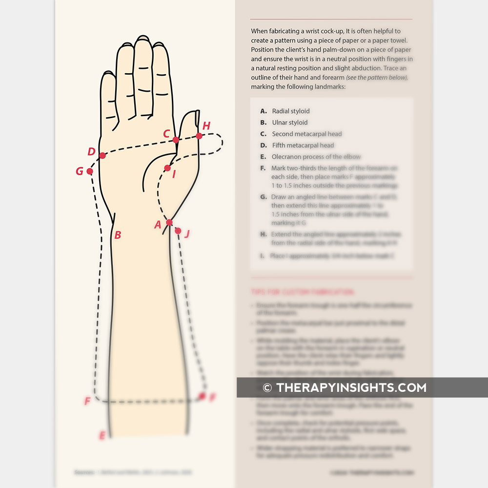
- A - Radial styloid
- B - Ulnar styloid
- C - 2nd metacarpal head
- D - 5th metacarpal head
- E - Olecranon process of the elbow
- F - Two-thirds the length of the forearm (both sides)
Diagram 3 - Classic Labelled Diagram (Lateral View)
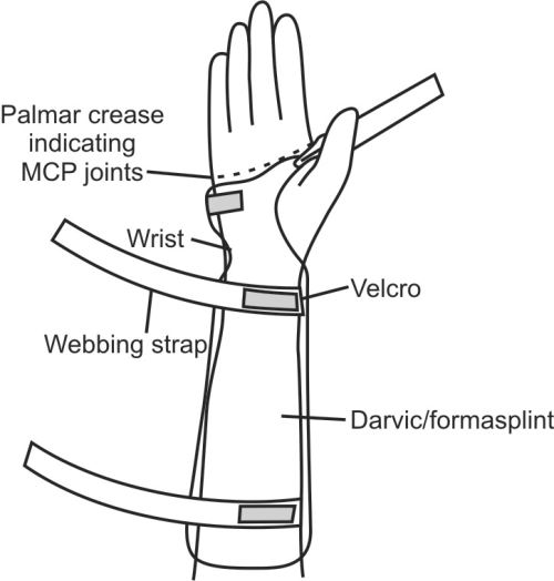
- Palmar crease indicating MCP joints (proximal border of splint)
- Wrist strap
- Velcro fastening
- Webbing strap
- Darvic/formasplint (the rigid base material)
Key Design Features
| Feature | Detail |
|---|---|
| Wrist position | 0-30 degrees of extension (neutral to slight dorsiflexion) |
| Forearm trough | 2/3 length of forearm, 1/2 circumference |
| Proximal border | Just distal to MCP joints (palmar crease) |
| Distal border | 2/3 up the forearm |
| Thumb | Free (thumb not included) |
| Type | Volar (palmar surface) immobilization orthosis |
Common Indications
- Carpal tunnel syndrome (night splinting)
- Radial nerve palsy / wrist drop
- Wrist tendinitis
- Distal radius fracture (non-displaced)
- Wrist sprain
- Rheumatoid arthritis (resting position)
Note from Tintinalli's Emergency Medicine: The cock-up splint should be avoided for acute wrist and carpal fractures because these injuries are typically caused by forceful dorsiflexion - reproducing that position causes significant pain. It is better suited for non-traumatic conditions requiring wrist support.
Diagram of coockup wrist splint
Medical diagram of a cock-up wrist splint (volar wrist immobilization orthosis), showing lateral and palmar views. Label the following parts clearly: forearm trough (extends 2/3 length of forearm), metacarpal bar (palmar bar), hypothenar bar, wrist in 20-30 degrees extension, velcro straps, proximal border just distal to MCP joints at palmar crease, thumb free and unrestricted. Clean anatomical illustration style with clear arrows and labels, white background, medical textbook quality.
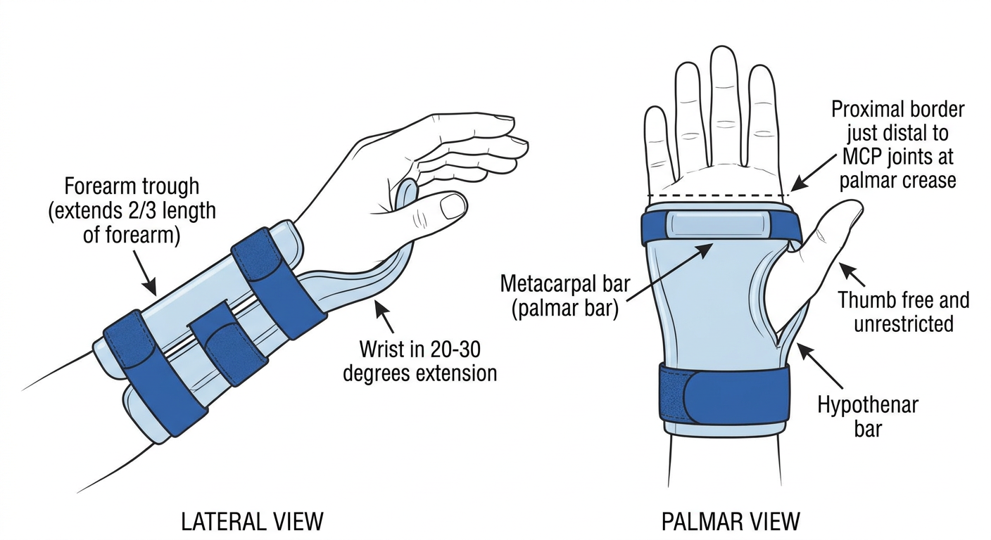
Cock-Up Wrist Splint (Volar Wrist Immobilization Orthosis)
Key Components
| Part | Description |
|---|---|
| Forearm trough | Covers 2/3 length of forearm, 1/2 its circumference |
| Metacarpal bar (palmar bar) | Supports the transverse metacarpal arch |
| Hypothenar bar | Prevents ulnar deviation, maintains neutral hand position |
| Velcro straps | Typically 3 straps - at forearm, wrist, and hand |
| Wrist position | 0-30 degrees of extension (neutral to slight dorsiflexion) |
| Proximal border | Just distal to the palmar crease (MCP joint level) |
| Thumb | Left free for functional use |
Indications
- Carpal tunnel syndrome (especially night splinting)
- Wrist drop from radial nerve palsy
- Wrist tendinitis / de Quervain's tenosynovitis
- Distal radius fractures (stable, non-displaced)
- Wrist sprain
- Rheumatoid arthritis resting position
Important Clinical Note
Diagram of volar wrist splint
Detailed medical diagram of a volar wrist splint shown from two angles: palmar (front) view and lateral (side) view. The diagram should clearly label: rigid volar shell/trough along the palm and forearm, wrist positioned in neutral to slight extension (0-20 degrees), forearm trough extending two-thirds up the forearm, thumb hole or thumb free, three velcro closure straps (at distal forearm, wrist, and hand), proximal border ending just below the MCP joints at the distal palmar crease, distal border at the proximal forearm, padding layer between skin and rigid shell. Use clean anatomical illustration style, labeled arrows, white background, medical textbook quality diagram.
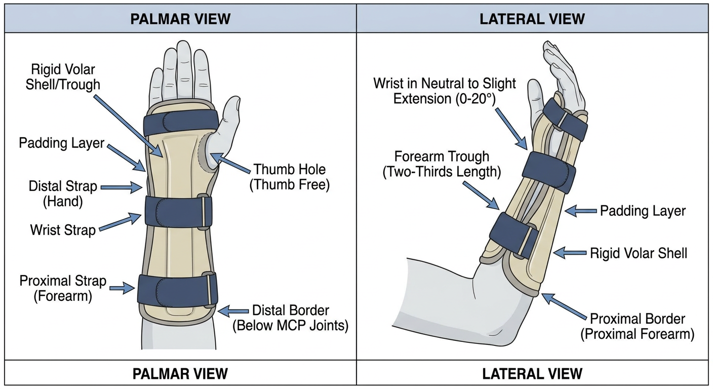
Volar Wrist Splint - Key Features
Structural Components
| Component | Detail |
|---|---|
| Volar shell | Rigid or semi-rigid trough on the palmar (front) surface |
| Forearm trough | Extends 2/3 the length of the forearm |
| Wrist position | Neutral to 0-20° extension |
| Padding layer | Foam/cotton between skin and rigid shell |
| Velcro straps | 3 straps - hand, wrist, and forearm |
| Proximal border | Stops at the distal palmar crease (MCP joint level) |
| Thumb | Free - unrestricted movement |
| Fingers | All four fingers free for functional use |
Volar vs. Cock-Up Splint
- Volar splint = describes the surface it covers (palmar side)
- Cock-up splint = describes the wrist position (dorsiflexed / extended) Both refer to the same orthosis when the wrist is held in extension.
Common Indications
- Carpal tunnel syndrome (night splinting)
- Wrist sprain or strain
- Distal radius fracture (stable)
- Radial nerve palsy / wrist drop
- De Quervain's tenosynovitis
- Post-operative wrist immobilization
- Rheumatoid arthritis flare
Fabrication Tips
- Material: thermoplastic (e.g., Orfit, Aquaplast), plaster, or prefabricated
- Width: covers half the forearm circumference
- Mold with wrist in slight extension while material is warm
- Smooth and flare all edges to prevent pressure sores over bony prominences (radial styloid, ulnar styloid)
Diagram of dorsal wrist splint
Detailed medical diagram of a dorsal wrist splint shown from two angles: dorsal (back of hand) view and lateral (side) view. Clearly label: rigid dorsal shell running along the back of the hand and forearm, wrist positioned in neutral to slight extension (0-30 degrees), forearm trough on dorsal surface extending two-thirds up the forearm, thumb completely free, three velcro closure straps on the palmar side (at distal forearm, wrist, and hand), proximal border ending just proximal to the MCP joints on the dorsum, padding layer between skin and rigid shell, palmar surface left open for sensory feedback and grip. Use clean anatomical illustration style with labeled arrows, white background, medical textbook quality diagram.
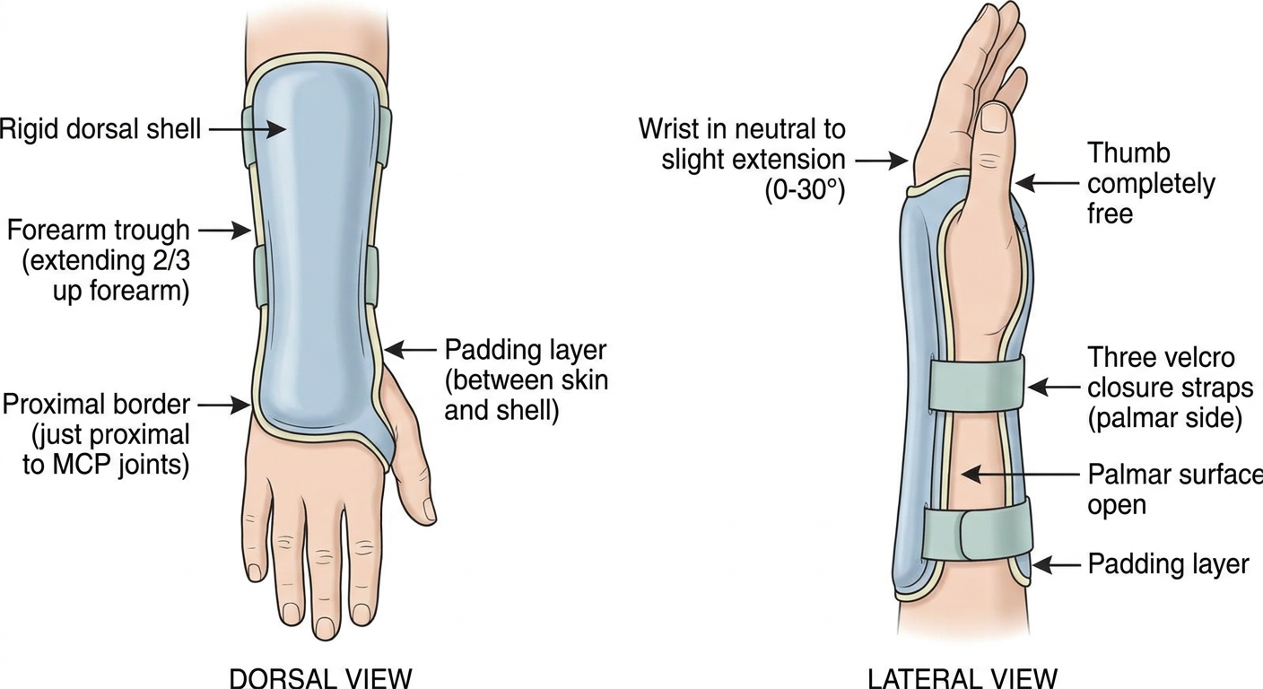
Dorsal Wrist Splint - Key Features
Structural Components
| Component | Detail |
|---|---|
| Dorsal shell | Rigid/semi-rigid trough on the back (dorsal) surface of hand and forearm |
| Forearm trough | Extends 2/3 the length of the forearm, dorsal surface |
| Wrist position | Neutral to 0-30° extension |
| Padding layer | Foam/cotton between skin and shell |
| Velcro straps | Cross from dorsal shell to palmar side for closure |
| Proximal border | Just proximal to MCP joints on the dorsum |
| Palmar surface | Left fully OPEN - key distinguishing feature |
| Thumb & fingers | All free for unrestricted movement |
Dorsal vs. Volar Splint - Key Differences
| Feature | Volar (Cock-Up) | Dorsal |
|---|---|---|
| Shell location | Palmar surface | Dorsal (back) surface |
| Palmar sensation | Reduced | Fully preserved |
| Grip function | Partially restricted | Better preserved |
| Straps | On dorsal side | On palmar side |
| Best for | Carpal tunnel, resting | Carpal tunnel (preferred), pediatrics, sensory-sensitive patients |
Advantages of Dorsal Design
- Palmar surface remains open - preserves tactile sensation and grip
- Better tolerated for daytime/functional use
- Preferred in carpal tunnel syndrome by many hand therapists as it keeps the wrist in neutral without compressing the palm
- Less pressure on the median nerve at the carpal tunnel
Common Indications
- Carpal tunnel syndrome (especially daytime use)
- Wrist drop (radial nerve palsy)
- Pediatric wrist immobilization
- Post-surgical wrist support where palmar sensation must be preserved
- Patients who need to grip objects while wearing the splint
Diagram of resting and splint
Detailed medical diagram of a hand resting splint (resting hand splint / hand resting orthosis) shown from palmar view and lateral view. Clearly label all components: wrist positioned in 10-20 degrees extension, MCP joints in 45-60 degrees flexion, IP joints in slight flexion (10-20 degrees), thumb in palmar abduction and opposition, trough extending from fingertips to two-thirds up the forearm on the volar surface, finger gutter/trough supporting all four fingers, thumb post or opponens bar supporting the thumb, three velcro closure straps at forearm, wrist, and hand, padding layer, flared edges at bony prominences (radial styloid, ulnar styloid, MCP joints). Clean anatomical medical illustration with labeled arrows, white background, textbook quality.
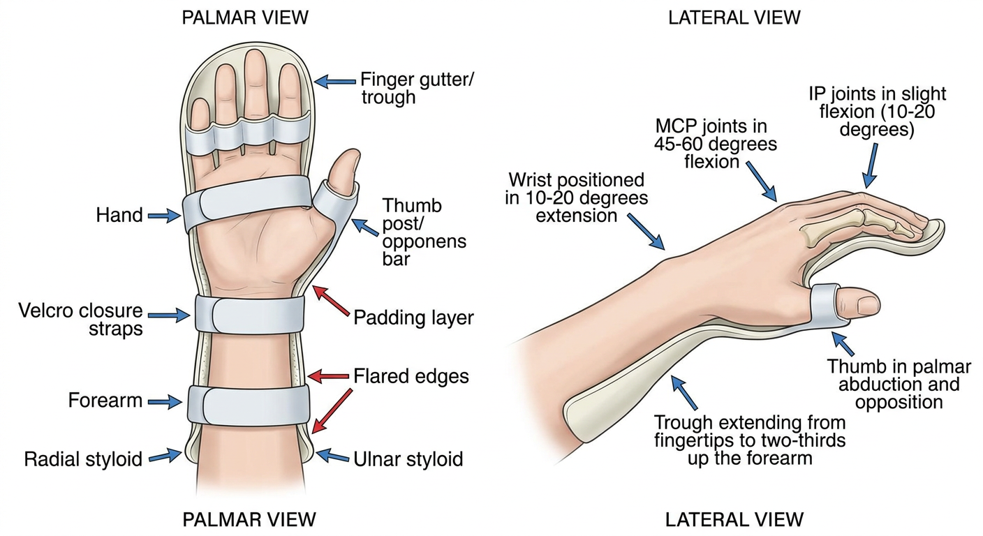
Resting Hand Splint (Resting Hand Orthosis)
Prescribed Joint Positions
| Joint | Position |
|---|---|
| Wrist | 10-20° extension |
| MCP joints | 45-60° flexion |
| PIP / DIP joints | 10-20° flexion (slight) |
| Thumb | Palmar abduction + opposition (midway between radial & palmar abduction) |
Structural Components
| Component | Detail |
|---|---|
| Volar trough | Extends from fingertips to 2/3 up the forearm |
| Finger gutter | Supports all four fingers in slight flexion |
| Thumb post / opponens bar | Holds thumb in abduction and opposition |
| Velcro straps | 3-4 straps: fingers, hand, wrist, and forearm |
| Padding | Foam lining over all bony prominences |
| Material | Low-temperature thermoplastic (custom) or prefabricated |
Resting Splint vs. Cock-Up/Volar Splint
| Feature | Resting Hand Splint | Cock-Up / Volar Splint |
|---|---|---|
| Coverage | Fingertips to forearm | Proximal to MCPs to forearm |
| Fingers | Included (in slight flexion) | Free |
| Thumb | Included (abducted) | Free |
| MCP position | 45-60° flexion | Free |
| Purpose | Prevent deformity, rest entire hand | Wrist immobilization only |
| Use | Night resting, spasticity, RA | CTS, tendinitis, wrist sprain |
Common Indications
- Rheumatoid arthritis - resting inflamed joints, preventing ulnar drift and swan-neck deformity
- Stroke / hemiplegia - preventing flexion contracture of a spastic hand
- Burns of the hand - anti-deformity position
- Peripheral nerve injuries (median, ulnar, radial)
- Post-operative hand and wrist surgery
- Juvenile idiopathic arthritis - night splinting
Key Clinical Note
Resting hand splint proper diagram
resting hand splint diagram labeled anatomy orthosis
Resting Hand Splint (Resting Hand Orthosis / Resting Pan Splint)
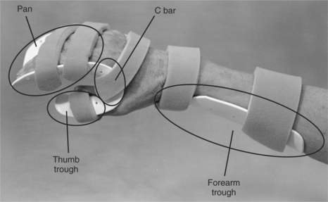
Diagram 1 - Components Overview + Fabrication Pattern
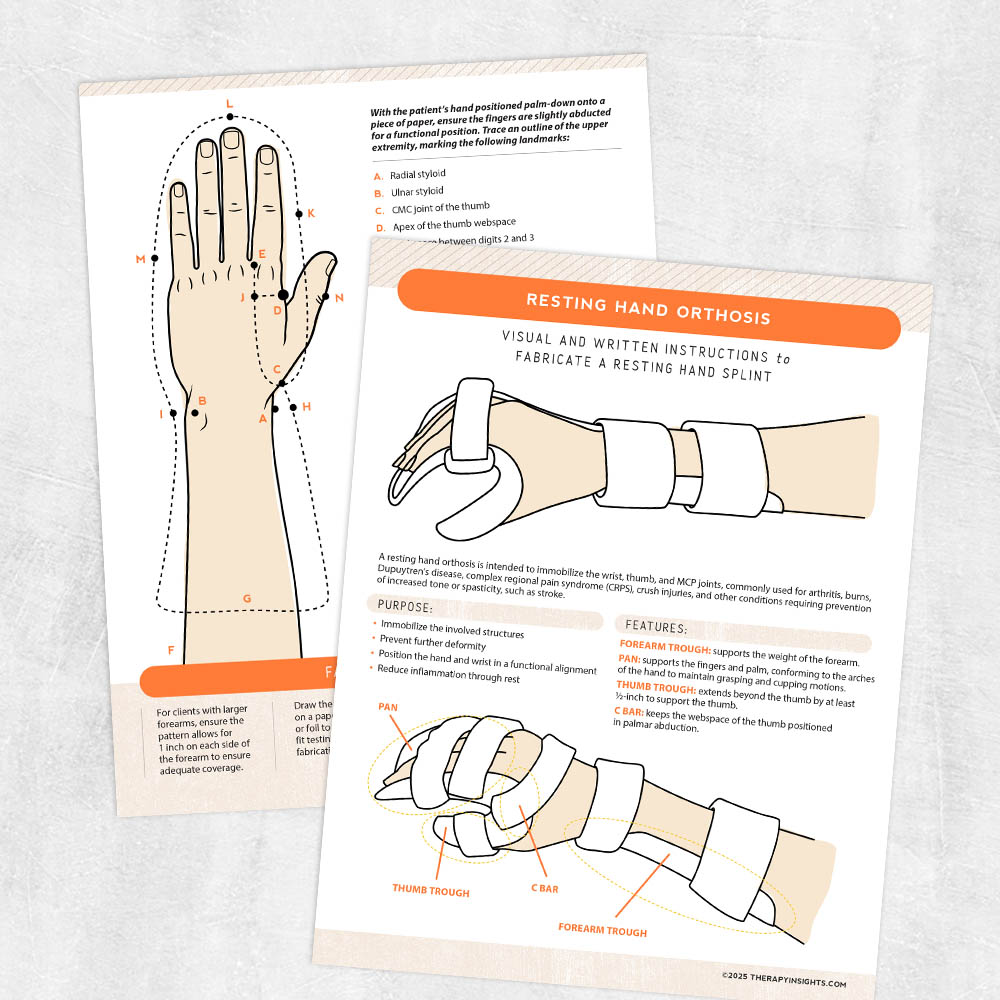
- Pan - supports all fingers and the palm, conforming to the arches of the hand for cupping motion
- Thumb trough - extends at least 1/2 inch beyond the thumb tip to support it
- C bar - keeps the thumb webspace open in palmar abduction
- Forearm trough - supports the weight of the forearm
Diagram 2 - Fabrication Pattern with Anatomical Landmarks
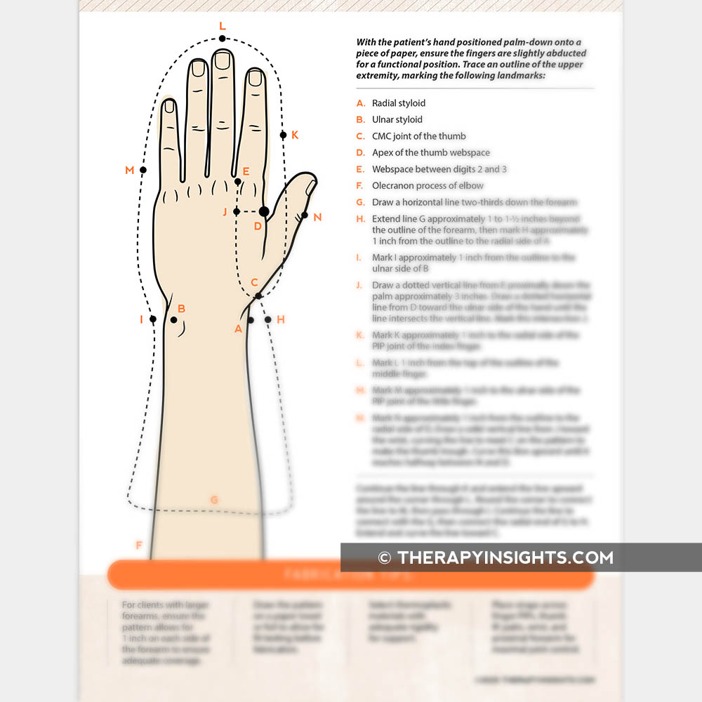
- A - Radial styloid
- B - Ulnar styloid
- C - CMC joint of the thumb
- D - Apex of the thumb webspace
- E - Webspace between digits 2 and 3
- F - Olecranon process of the elbow
- G - 2/3 down the forearm (proximal border)
- K, L, M - Radial side, tip, and ulnar side of finger PIP joints
Diagram 3 - Clinical Photo with Labels
Prescribed Positions
| Joint | Position |
|---|---|
| Wrist | 10-20° extension |
| MCP joints | 45-60° flexion |
| PIP / DIP joints | 10-20° flexion |
| Thumb | Palmar abduction, CMC midway |
Four Main Components
| Component | Function |
|---|---|
| Forearm trough | Bears weight of the forearm; 2/3 forearm length |
| Pan | Supports all fingers and palm; preserves metacarpal arch |
| Thumb trough | Immobilizes thumb; extends past thumb tip |
| C bar | Maintains thumb webspace; prevents first web contracture |
Indications
- Rheumatoid arthritis (prevents ulnar drift, swan-neck, boutonniere)
- Burns of the hand (anti-deformity position)
- Stroke / spasticity (prevents flexion contracture)
- Peripheral nerve injuries
- Crush injuries, CRPS
- Dupuytren's contracture post-op
- Any condition requiring complete hand rest and deformity prevention
Diagram to draw
What diagram would you like to draw?
What format do you need?
A clean, fully labeled medical diagram of a resting hand splint (resting pan orthosis) suitable for drawing in an exam or clinical notes. Show lateral (side) view and palmar (front) view side by side. Label with clear arrows: (1) Forearm trough - extends 2/3 up the forearm, (2) Pan - supports fingers and palm maintaining metacarpal arch, (3) Thumb trough - extends past thumb tip, supports thumb, (4) C bar - maintains first web space in palmar abduction, (5) Velcro straps x3, (6) Wrist in 10-20 degrees extension, (7) MCP joints in 45-60 degrees flexion, (8) IP joints in slight flexion 10-20 degrees, (9) Thumb in palmar abduction. Black and white line drawing style, clean simple lines, white background, like a textbook diagram that a student can copy and reproduce by hand.
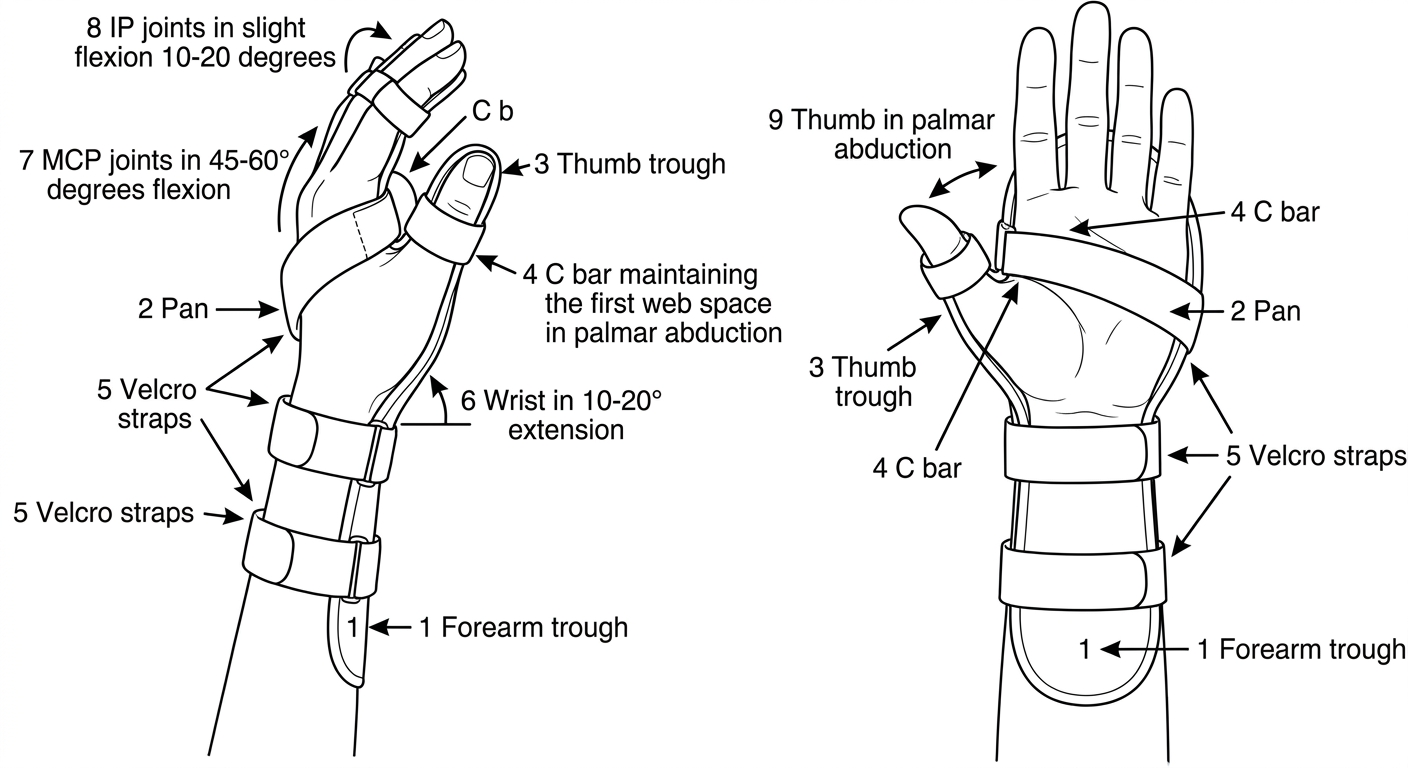
How to Draw a Resting Hand Splint - Step by Step
Step 1 - Draw the hand outline
Step 2 - Add the forearm trough
Step 3 - Add the pan
Step 4 - Add the thumb trough + C bar
- Draw a separate wing/trough for the thumb, positioned in palmar abduction
- Add the C bar across the first webspace to maintain the thumb opening
Step 5 - Add straps
Step 6 - Label joint positions
- Wrist: 10-20° extension
- MCPs: 45-60° flexion
- IPs: 10-20° flexion
- Thumb: palmar abduction
Quick Label Checklist for Your Diagram
| Label | Location |
|---|---|
| Forearm trough | Proximal part of splint |
| Pan | Distal palm + finger section |
| Thumb trough | Lateral thumb piece |
| C bar | First webspace |
| Velcro straps | x3 across the splint |
| Wrist 10-20° extension | Wrist angle |
| MCP 45-60° flexion | Knuckle angle |
| IP 10-20° flexion | Finger joint angle |