
Steps of mvd of trigeminal nerve
microvascular decompression trigeminal nerve MVD surgery
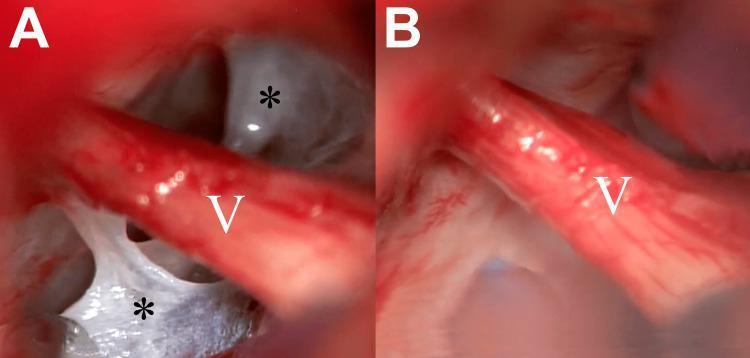
Intraoperative microscopic photographs illustrating microvascular decompression (MVD) surgery in the left cerebellopontine angle for trigeminal neuralgia. Image A shows the trigeminal nerve (labeled V) partially obscured by thickened, opaque, and web-like arachnoid membranes (indicated by asterisks). These pathological membranes are seen adhering to the nerve root and adjacent neurovascular structures, potentially contributing to nerve irritation or compression through arachnoiditis. Image B displays the same surgical field following the meticulous removal of the thickened arachnoid tissue. This neurolysis achieves 'release' of the nerve, providing a clear, unobstructed view of the trigeminal nerve root and allowing for definitive exploration of any underlying neurovascular conflict. The comparison highlights the clinical importance of arachnoid dissection in posterior fossa functional neurosurgery to ensure adequate nerve decompression and visualization.
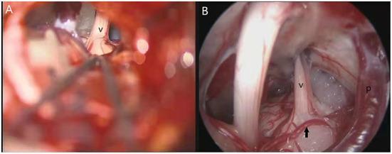
This side-by-side clinical comparison illustrates the differences between microscopic and endoscopic visualizations during microvascular decompression (MVD) surgery for trigeminal neuralgia. Image A displays the microscopic view through a retrosigmoid approach, showing the trigeminal nerve (v) partially visible within a narrow surgical corridor, with neurosurgical instruments in the foreground. Image B presents the endoscopic view of the same anatomical area, providing a wider perspective and superior depth perception. Key labeled structures in the endoscopic field include the trigeminal nerve (v), the superior petrosal vein (p) positioned to the right, and a hidden 'responsible artery' (indicated by a black arrow) located inferior to the nerve, which was not clearly visible under the microscope. This comparison highlights the educational concept of neuro-endoscopic superiority in identifying neurovascular conflict (NVC), particularly for vessels positioned on the dorsal or inferior aspects of the nerve that might be obscured by the restricted line-of-sight inherent to microscopic surgical views.
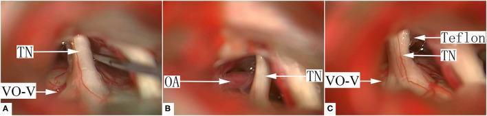
Microvascular decompression (MVD) for trigeminal neuralgia involving venous offending vessels (VO-VREZ). This three-panel intraoperative clinical photograph (A, B, C) demonstrates the neurovascular relationship at the cerebellopontine angle. (A) Shows the trigeminal nerve (TN) in direct contact with a venous offending vessel on the ventral side of the root entrance/exit zone (VO-V), where the vein is largely covered by the nerve root. A surgical dissector is visible manipulating the tissue. (B) Reveals a suspected offending artery (OA) situated behind the TN, contributing to the neurovascular conflict. (C) Illustrates the surgical resolution where shredded Teflon interposition material is placed between the nerve root and the offending vessels. This mechanical decompression separates the TN from the VO-V and OA to relieve nerve compression. The series highlights surgical management of Group II, Type A venous compression, showcasing the transition from initial neurovascular contact to the final decompression with synthetic material.
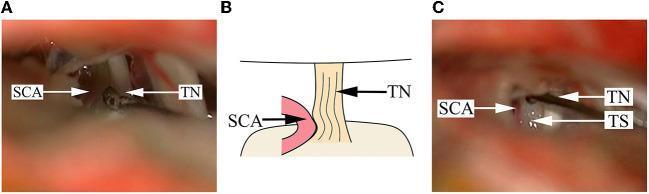
This composite educational image illustrates a microvascular decompression (MVD) procedure for trigeminal neuralgia caused by neurovascular conflict. Panel A is an intraoperative clinical photograph showing the superior cerebellar artery (SCA) severely impacting the cisternal segment of the trigeminal nerve (TN). The nerve root appears visibly dark, deformed, and depressed due to chronic arterial compression. Panel B provides a simplified anatomical diagram of the neurovascular conflict, highlighting the point of contact where the arterial loop displaces the nerve fiber bundle. Panel C is a postoperative intraoperative photograph demonstrating the surgical resolution: the SCA has been mobilized away from the TN, and a white, fibrous Teflon sponge (TS) has been interposed as a permanent cushion between the vessel and the nerve root. This content demonstrates key surgical landmarks in the cerebellopontine angle and the mechanical basis of trigeminal decompression.
microvascular decompression trigeminal neuralgia surgical steps technique retrosigmoid
https://mayfieldclinic.com/pe-mvd.htm
Microvascular Decompression (MVD) of the Trigeminal Nerve
Preoperative Preparation
- MRI brain with FIESTA/CISS sequences + MRA to identify neurovascular conflict
- Audiometric baseline (hearing and brainstem auditory evoked potentials - BAEPs)
- Informed consent including risks of CSF leak, hearing loss, facial numbness, cerebellar injury, stroke, and death (~1%)
- General anesthesia; IV antibiotics
Step 1 - Patient Positioning
- Patient is placed in the lateral decubitus (park-bench) position with the symptomatic side up, or in the semi-sitting position (some centres)
- The head is fixed in a 3-pin Mayfield skull clamp attached to the operating table
- The head is flexed slightly forward and tilted away from the surgeon to open the retrosigmoid corridor
- Intraoperative neuromonitoring is set up: BAEPs (to protect hearing/CN VIII) and facial nerve EMG
Step 2 - Skin Incision and Exposure
- A 3-4 cm curved vertical incision is made ~2 cm posterior and inferior to the mastoid process (behind the ear)
- The skin, subcutaneous tissue, and posterior cervical muscles (sternocleidomastoid, splenius capitis) are incised and retracted
- The occipital bone is exposed; the mastoid emissary vein is identified and controlled with bone wax if encountered
Step 3 - Retrosigmoid Craniectomy / Craniotomy
- A ~2.5 x 2.5 cm bur-hole or craniotomy is made in the occipital bone just medial to the sigmoid sinus and below the transverse sinus
- The junction of the sigmoid and transverse sinuses (the "sinodural angle") is the critical landmark
- The bone flap is elevated (or a craniectomy is performed) with a high-speed drill and Kerrison rongeurs
- The dura mater is exposed overlying the posterior fossa cerebellum
Step 4 - Dural Opening
- The dura is opened in a cruciate or C-shaped fashion, taking care not to injure the underlying sigmoid sinus
- The dural flaps are tacked back with sutures
- CSF is gently released from the cisterna magna by arachnoid opening inferiorly, which relaxes the cerebellum and avoids the need for forceful retraction
Step 5 - Microsurgical Approach to the Cerebellopontine Angle (CPA)
- Under the operating microscope, the cerebellum is gently retracted superiorly and medially using a self-retaining retractor or dynamic retraction
- The cerebellopontine cistern is entered; the arachnoid is incised sharply
- The surgeon navigates along the petrosal surface of the cerebellum toward the brainstem
- CN VII and CN VIII (facial and vestibulocochlear nerves) are identified first as they exit the IAC and serve as anatomical landmarks
- The trigeminal nerve (CN V) is located superiorly, running horizontally toward Meckel's cave
Step 6 - Arachnoid Dissection and Nerve Exposure
- Thickened arachnoid adhesions around CN V are carefully dissected using fine microsurgical scissors and bipolar forceps
- The root entry zone (REZ) of CN V at the pons is fully exposed - this is the critical zone where demyelination occurs due to vascular pulsation
Step 7 - Identification of the Offending Vessel
- The surgeon carefully inspects the entire circumference of the trigeminal nerve REZ, including the ventral, dorsal, and inferior aspects (an endoscope may be used to look around the nerve)
- The offending vessel is identified (most commonly the SCA looping inferiorly and compressing the superior aspect of CN V at the REZ)
- The vessel may be adherent, indenting, or distorting the nerve
- All neurovascular contacts must be documented; some cases involve multiple offending vessels
Step 8 - Decompression (The Key Step)
A. Transposition (preferred for arteries)
- The offending artery is mobilized away from the nerve using a dissector
- A small pledget of shredded Teflon felt (PTFE) is interposed between the vessel and the nerve root as a permanent cushion, preventing re-contact
- The sponge must be sized appropriately - not too large (can cause new compression)
- Some surgeons use the "sling" technique: the vessel is transposed and fixed to the dura with a suture (5-0 prolene), keeping it away from the nerve permanently without any foreign material touching the nerve
B. Coagulation and division (for veins)
- Offending veins (e.g., superior petrosal vein tributaries) are bipolar coagulated and divided since they cannot be safely transposed
Step 9 - Verification of Decompression
- The decompression is inspected under the microscope (and optionally with a 30-degree angled endoscope) to confirm no residual vascular contact
- The nerve should lie free without any pulsating vessel touching it
- BAEPs are monitored throughout to detect any cochlear/brainstem ischemia
Step 10 - Closure
- The microsurgical field is irrigated copiously with warm saline
- Meticulous hemostasis is achieved
- The dura is closed watertight with 4-0 sutures (a dural patch/fascia graft may be used if needed)
- The craniectomy defect is filled with cranioplasty material (titanium mesh, PMMA cement, or the bone flap is replaced)
- Muscles and fascia are closed in layers
- Skin is closed with interrupted sutures or staples
- A subgaleal drain may be placed
Postoperative Care
- Patient is monitored in ICU/step-down for 24 hours
- Head of bed elevated 30 degrees
- Watch for: CSF leak, hearing loss, facial weakness (CN VII), cerebellar edema, hematoma
- Hospital stay: typically 2-4 days
- Return to normal activity: 4-6 weeks
Outcomes
- Initial pain relief: >90% of patients after successful MVD
- Long-term cure: ~70-80% at 10 years (among the best of all TN procedures)
- The procedure preserves trigeminal sensation (unlike rhizotomy/ablative procedures)
- Recurrence is lower than Gamma Knife or radiofrequency ablation, per the Mayfield Clinic MVD overview and the NIH/PMC surgical TN review
Key Complications to Know
| Complication | Approximate Rate |
|---|---|
| CSF leak | 2-5% |
| Hearing loss (ipsilateral) | 1-3% |
| Facial weakness (CN VII) | <1% (transient) |
| Trigeminal sensory loss | <3% |
| Cerebellar injury/hematoma | <1% |
| Mortality | <0.5% |