
Bone cement implementation syndrome for 10 marks answer
"bone cement implantation syndrome"
bone cement implantation syndrome embolism echocardiography hip arthroplasty
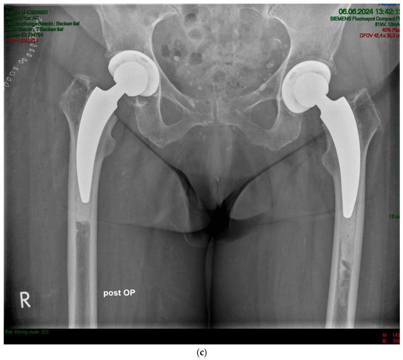
This diagnostic image is an anteroposterior (AP) pelvic X-ray demonstrating bilateral total hip arthroplasty in an 85-year-old female patient with osteoarthritis. The image shows sequential implantation of cemented A2 femoral stems. Both the left and right femurs exhibit radiopaque stainless-steel implants consisting of a femoral head articulating with an acetabular component and a calcar-guided stem extending into the femoral canal. A visible cement mantle surrounds both stems, appearing as a moderately radiopaque layer between the dense metal implant and the cortical bone. On the right side (labeled 'R'), the cement stopper is positioned immediately distal to the stem tip. On the left side, there is evidence of slight distalization of the cement stopper. The pelvic bone quality shows signs of reduced density consistent with age-related changes (Dorr Type B-C femora) and heterogeneity suggesting bone remodeling. This image illustrates postoperative orthopedic positioning and the use of cemented backups in patients with poor bone quality.
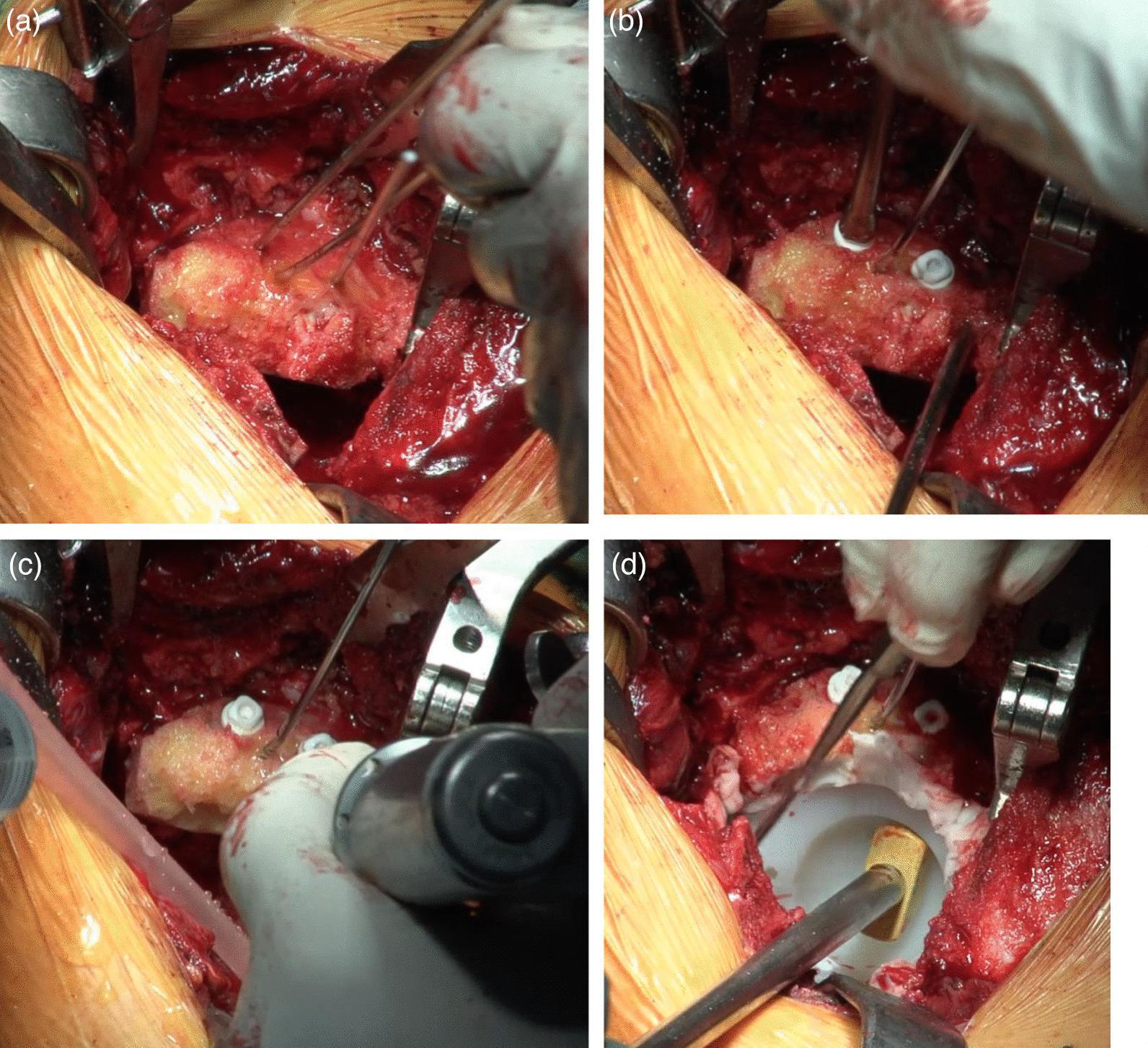
This four-panel series of intraoperative clinical photographs details the surgical technique for structural bone grafting and socket implantation during a cemented total hip arthroplasty (cTHA) for acetabular dysplasia. Panel (a) demonstrates a roughly hemispherical femoral head autograft being positioned into the superior acetabular defect, secured temporarily with thin metallic Kirschner wires (K-wires). Panel (b) shows the definitive fixation of the graft using bioabsorbable screws (Superfixorb) with white washers, positioned superiorly to allow for subsequent acetabular reaming. A screw insertion tool is visible. In panel (c), the acetabular bed is re-reamed to create a spherical cavity involving both the native bone and the graft. Panel (d) displays the final implantation of a white highly cross-linked polyethylene (HXLPE) non-flanged socket. The socket is fixed with polymethylmethacrylate (PMMA) bone cement and is being seated with a gold-headed tamping instrument. The bone graft provides structural augmentation to the superior acetabular roof, increasing the contact surface for the cemented implant.
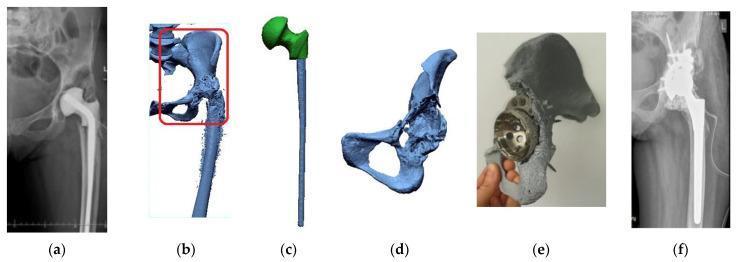
A multi-panel figure illustrating the computer-aided design (CAD) and 3D-printing workflow for complex revision hip arthroplasty. (a) Pre-operative X-ray of the hip showing a temporary antibiotic-loaded cement spacer (SPACER) in situ following primary implant removal. (b) 3D volumetric reconstruction of the pelvis and proximal femur derived from CT data, with a red bounding box indicating the region of interest for surgical planning. (c) Digital segmentation and isolation of the hip endoprosthesis components, including the femoral stem and head. (d) A refined 3D digital model of the hemi-pelvis showing significant acetabular bone loss. (e) A tangible 1:1 scale 3D-printed physical model of the pelvis used for intraoperative orientation and pre-fitting the acetabular cup and fixation screws. (f) Post-operative diagnostic radiograph showing the successful implantation of the revision prosthesis, including an acetabular cup stabilized with multiple screws and a long-stem femoral component. The sequence demonstrates the integration of reverse engineering and additive manufacturing to manage complex anatomical defects and improve surgical precision in orthopedic surgery.
Bone Cement Implantation Syndrome (BCIS)
Definition
- Barash, Cullen, and Stoelting's Clinical Anesthesia, 9e
- Miller's Anesthesia, 10e
Bone Cement (Polymethylmethacrylate - PMMA)
-
Hardening and expansion against prosthetic components
-
Intramedullary pressure spikes >500 mm Hg (vs. <100 mm Hg without cement; can peak at 680 mm Hg)
-
Embolization of fat, bone marrow, cement particles, and air into venous channels
-
Morgan & Mikhail's Clinical Anesthesiology, 7e
-
Miller's Anesthesia, 10e
Pathophysiology / Mechanisms
| Mechanism | Effect |
|---|---|
| Intramedullary hypertension during cementation | Forces fat, marrow, air, and thrombi into venous channels |
| Embolization (fat, marrow debris, cement, thrombi) | Occludes pulmonary microvasculature → RV failure |
| Methyl methacrylate monomer absorption | Systemic vasodilation, decreased SVR, direct cardiotoxicity |
| Tissue thromboplastin release | Platelet aggregation, microthrombus formation |
| Histamine release and complement activation | Pulmonary vasoconstriction, endothelial damage |
| Cytokine / COX-product release (during reaming) | Pulmonary vasoconstriction, microthrombi |
Note: MMA monomer levels in vivo are too low to account for the full severity of BCIS. Fat/marrow embolization is now considered the primary driver, overlapping extensively with fat embolism syndrome (FES).
Clinical Features
-
Hypoxia - increased pulmonary shunt (most common)
-
Hypotension - from vasodilation and decreased cardiac output
-
Cardiac arrhythmias - including heart block and sinus arrest
-
Pulmonary hypertension - increased pulmonary vascular resistance (PVR)
-
Right ventricular failure - due to acute rise in RV afterload
-
Decreased cardiac output
-
Altered mental status (in severe cases)
-
Cardiac arrest (in the most severe cases)
-
Morgan & Mikhail's Clinical Anesthesiology, 7e (Key Concept 1)
Grading of BCIS (Donaldson Classification)
| Grade | Features |
|---|---|
| Grade 1 | Moderate hypoxia (SpO2 <94%) OR hypotension (>20% fall in SBP) |
| Grade 2 | Severe hypoxia (SpO2 <88%) OR hypotension (>40% fall in SBP) OR unexpected loss of consciousness |
| Grade 3 | Cardiovascular collapse requiring CPR |
Risk Factors
- Advanced age (>70 years), osteoporosis
- Pre-existing pulmonary hypertension or right ventricular failure
- Metastatic bone disease / pathological fractures
- Poor cardiorespiratory reserve
-
Previously uninstrumented femoral canal (smooth sclerotic inner surface = more permeable)
-
Long-stem prosthesis
-
Total hip arthroplasty for pathologic fracture
-
Large quantity of cement used
-
High-pressure cementing technique
-
Miller's Anesthesia, 10e
Prevention / Surgical Strategies
- Pulsatile lavage (high-pressure) of the medullary canal - removes fat/marrow debris before cementing
- Distal venting holes drilled in the long bone - reduces intramedullary pressure (though may cause cement extravasation)
- Vacuum mixing of cement - reduces porosity and embolization
- Use of cementless prosthesis - strongly preferred in high-risk patients
- Pre-oxygenation - increase FiO2 to 1.0 before cementing
- Fluid loading before cement insertion - maintain euvolemia
- Communication between surgeon and anesthesiologist at time of cementation
Monitoring
- Arterial line (mandatory in high-risk cases) - enables beat-to-beat BP monitoring and early detection
- Central venous catheter - consider in high-risk or medically fragile patients
- Pulmonary artery catheter - in patients with known pulmonary hypertension when cementation cannot be avoided
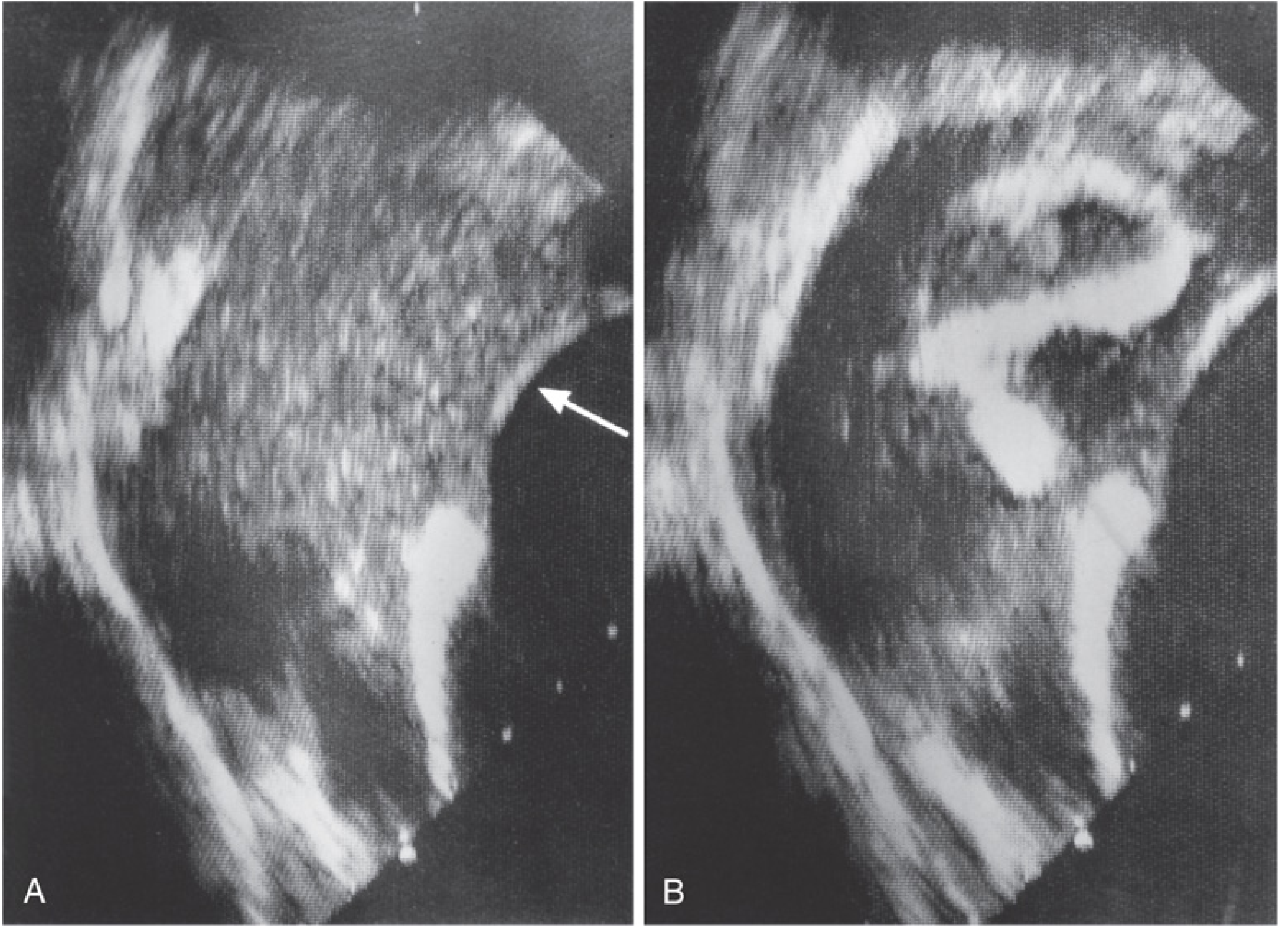
- Intraoperative TEE - gold standard for detecting intracardiac emboli in real time
Management
| Step | Intervention |
|---|---|
| Airway/Breathing | Increase FiO2 to 1.0; ventilatory support/mechanical ventilation if needed |
| Circulation | Aggressive fluid resuscitation to maintain preload |
| Vasopressors | Epinephrine (drug of choice) - supports RV function and offloads RV afterload; vasopressin and norepinephrine also used |
| Inotropes | For RV failure: epinephrine, dobutamine |
| CPR | For Grade 3 / cardiac arrest |
| Surgeon notification | Pause surgery; defer second-side arthroplasty if major hemodynamic instability occurs during first hip |
Goal of vasopressor therapy: offload the right ventricle by reducing RV afterload and maintaining systemic perfusion pressure.
- Miller's Anesthesia, 10e; Barash's Clinical Anesthesia, 9e
Key Points Summary
| Feature | Detail |
|---|---|
| Cement | PMMA - exothermic polymerization |
| Intramedullary pressure | >500-680 mm Hg (vs <100 mmHg without cement) |
| Primary mechanism | Fat/marrow embolization + MMA monomer toxicity |
| Main features | Hypoxia, hypotension, arrhythmias, RV failure |
| Timing | During or immediately after cementation / prosthesis insertion |
| Monitoring | Arterial line ± CVP ± TEE |
| Drug of choice | Epinephrine (for RV failure) |
| Best prevention | Cementless prosthesis in high-risk patients |
| Mortality | Can be fatal; cardiac arrest is the most severe presentation |
- Miller's Anesthesia, 2-Volume Set, 10e - Chapter 60, Bone Cement Implantation Syndrome section
- Morgan & Mikhail's Clinical Anesthesiology, 7e - Key Concept 1, Orthopedic Anesthesia chapter
- Barash, Cullen, and Stoelting's Clinical Anesthesia, 9e - Chapter 51, Special Considerations in Orthopedics
- Donaldson et al., Br J Anaesth 2009 - original BCIS classification paper
- Recent scoping review: Brokke et al., Br J Anaesth 2025 [PMID: 40634186]