
Step wise Operative procedure for Olecranon fracture treated with tension band wiring
Reading File
Now let me search the medical library for olecranon fracture tension band wiring content in parallel.
Finding Sources
Finding Sources
Campbell's Operative Orthopaedics has a dedicated section "OPEN REDUCTION AND INTERNAL FIXATION OF OLECRANON FRACTURE" - that's the most relevant. Let me read that along with the fixation types section.
Reading File
Reading File
Now let me read the dedicated ORIF olecranon section from Campbell's and the Rockwood & Green section on TBW technique:
Reading File
Reading File
I can see Rockwood & Green has detailed TBW content. Let me read the TBW technique section more fully, plus look for the specific operative steps in Campbell's:
Reading File
This section covers olecranon excision. I need the TBW section specifically. Let me read further:
Reading File
Excellent! I have the key surgical steps table and detailed technique. Let me read a bit more to capture all steps and the images:
Reading File
I now have comprehensive detail on the operative procedure. Let me also fetch the key illustration showing TBW steps:
Loading Image
Loading Image
Loading Image
I have all the content I need. Now let me also quickly check the full key surgical steps table that was truncated earlier, and retrieve the postoperative care details:
Reading File
I now have all the information needed to give a thorough, well-structured operative procedure. Here is the complete answer:
Olecranon Fracture: Tension Band Wiring (TBW) - Stepwise Operative Procedure
Indication: Simple, non-comminuted, transverse olecranon fractures proximal to the coronoid process, with a stable elbow. Not suitable for comminuted fractures, fractures associated with instability, or those distal to the coronoid.
Equipment required: 0.062-inch (1.6 mm) K-wires (x2), 20-gauge stainless steel cerclage wire, pointed reduction clamps (tenaculum), 2 mm drill bit, image intensifier (C-arm), radiolucent table.
PHASE 1: Preoperative Setup
Step 1 - Patient Positioning
- Place the patient in the lateral decubitus or prone position on a radiolucent table (either is preferred over supine as it provides better fluoroscopic access).
- A radiolucent arm positioner is placed under the arm to allow free elbow flexion and extension intraoperatively.
- The C-arm is brought in from the head of the table.
- The lateral position is generally preferred to reduce the risks associated with prone positioning, especially if operative time may be prolonged.
- If lateral/prone is not possible (e.g., regional anesthetic use), supine with a bump and the arm placed across the chest is acceptable, but imaging and reduction are more challenging.
- Obtain test fluoroscopic images before draping to confirm adequate image quality.
- A sterile tourniquet is kept available (used at surgeon's discretion).
PHASE 2: Surgical Approach
Step 2 - Skin Incision
- Make a posterior midline longitudinal incision from the tip of the olecranon distally.
- The incision is placed just radial to the tip of the olecranon - this deliberate offset provides better soft-tissue coverage over the implants.
- Raise full-thickness medial and lateral fasciocutaneous flaps.
Step 3 - Ulnar Nerve Identification
- Identify the ulnar nerve in the cubital tunnel early in the dissection so it can be protected throughout.
- It is NOT necessary to formally transpose or dissect it free of the cubital tunnel - identification alone is sufficient.
Step 4 - Fracture Exposure
- Develop the interval between extensor carpi ulnaris (ECU) and flexor carpi ulnaris (FCU).
- Expose the subcutaneous border of the ulna.
- On the ulnar side: elevate the FCU from the olecranon to visualize the joint.
- On the radial side: incise the anconeus fascia and elevate the anconeus from the olecranon fragment for additional visualization if needed.
PHASE 3: Fracture Reduction
Step 5 - Fracture Debridement and Joint Inspection
- Expose and clean the fracture edges carefully, preserving periosteum and any soft-tissue attachments to comminuted fragments.
- Inspect the articular surface for:
- Damage to the trochlea
- Intra-articular loose bodies
- A lateral capsulectomy may be helpful to confirm anatomic articular reduction and rule out impaction.
Step 6 - Fracture Reduction
- Reduce the fracture by extending the elbow - this relaxes the pull of the triceps.
- Place drill holes on the ulnar shaft - both radially and ulnarly - so that a pointed reduction clamp (tenaculum) can straddle the ulna: one tine in the drill hole, the other tine at the tip of the olecranon.
- Apply compression with the reduction clamp to hold the reduction.
- A shoulder hook or dental pick can assist in holding smaller fragments.
- Confirm anatomic articular reduction under direct vision and/or fluoroscopy.
PHASE 4: K-Wire Insertion
Step 7 - K-Wire Placement (the KEY step)
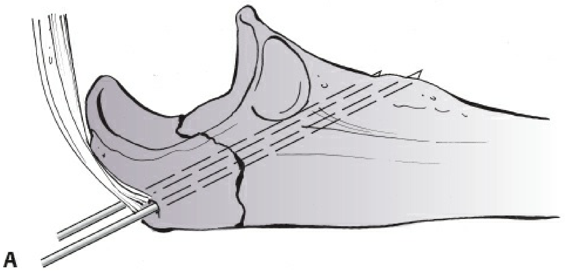
- Insert two 0.062-inch (1.6 mm) K-wires from the superior (dorsal) tip of the olecranon, directed distally in an intramedullary fashion.
- The wires must exit through the anteromedial cortex of the ulna (not the anterior cortex) - this engages solid cortical bone for anchorage.
- CRITICAL: Avoid lateral placement of K-wires - lateral exit near the biceps tuberosity risks impingement on the radial tuberosity, predisposing to rotational stiffness and radioulnar synostosis.
- CRITICAL: Avoid excessive length of the medial wire through the anteromedial cortex to prevent injury to the ulnar nerve (and median nerve anteriorly).
- Once the wires are across the fracture site and in satisfactory position, back them out slightly (1-2 mm) to accommodate the future impaction step.
- Confirm K-wire position on fluoroscopy in both AP and lateral views.
PHASE 5: Tension Band (Figure-of-Eight Wire) Construction
Step 8 - Transverse Drill Hole in Ulnar Shaft
- Place a transverse drill hole through the dorsal cortex of the ulnar shaft, distal to the coronoid process (approximately 3-4 cm distal to the fracture line).
- This hole provides the distal anchor point for the figure-of-eight wire.
Step 9 - Passing the Cerclage Wire
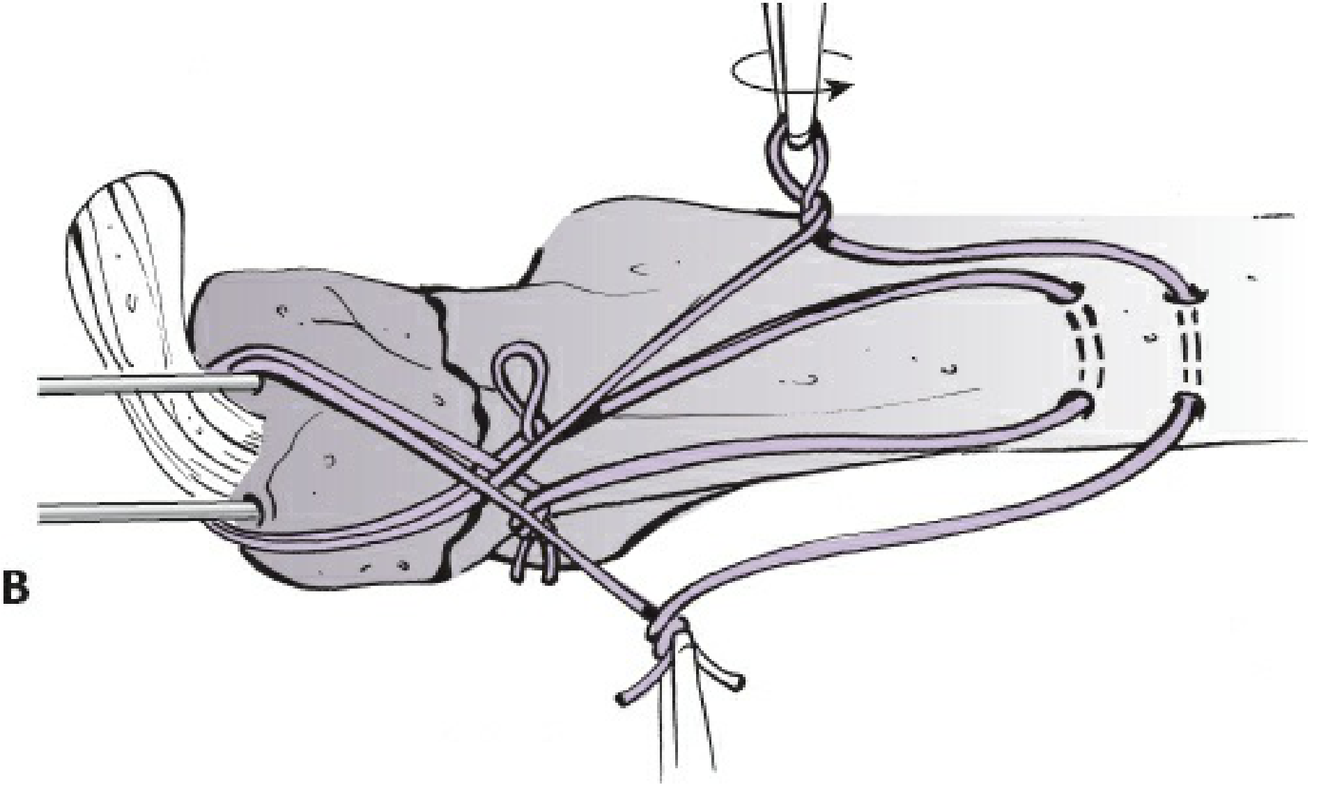
- Use an Angiocath catheter as a guide to pass the 20-gauge stainless steel wire.
- Pass the wire deep to the triceps tendon (underneath it) and around the proximal end of the K-wires.
- Thread the wire through the transverse drill hole distally to create a figure-of-eight configuration.
- One or two figure-of-eight tension bands may be constructed depending on fracture stability requirements.
Step 10 - Tensioning the Wire
- Tension the wire simultaneously on both the ulnar and radial sides to achieve equal, symmetric compression across the fracture.
- Unequal tensioning will cause rotational deformity at the fracture site.
- Verify articular reduction by direct inspection and fluoroscopy after tensioning.
PHASE 6: K-Wire Finishing
Step 11 - Bending and Impacting the K-Wires
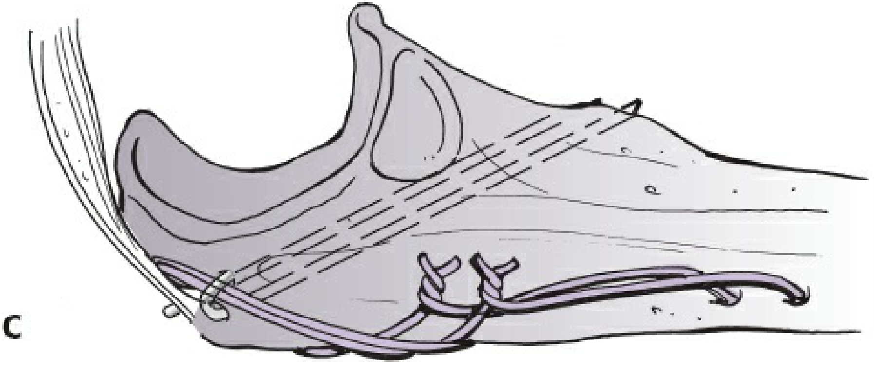
- Bend the proximal ends of both K-wires 180 degrees (hook shape).
- Through small incisions in the triceps tendon, impact (hammer) the bent K-wire tips into the olecranon beneath the triceps.
- The wires must be buried under the triceps - prominent wire tips are the leading cause of symptomatic hardware requiring removal (occurs in >50% of cases).
- Similarly, bury the cerclage wire knots to minimize subcutaneous prominence.
PHASE 7: Verification and Closure
Step 12 - Intraoperative Assessment
- Take the elbow through a full range of motion (particularly assess in full flexion) to confirm:
- Fixation is stable and does not toggle
- Reduction is maintained through the arc of motion
- No hardware impingement
- Obtain final fluoroscopic images in AP and lateral views.
Step 13 - Wound Closure
- Close the wound in layered fashion (deep fascia, subcutaneous tissue, skin).
- Layered closure is important to allow early range-of-motion while sutures are still in place.
- Apply a long-arm posterior splint in a semi-extended position.
PHASE 8: Postoperative Care
| Timepoint | Protocol |
|---|---|
| Day 0-2 | Long-arm splint in semi-extended position |
| 48 hours post-op | Splint and dressings taken down; ROM exercises begin |
| 0-6 weeks | Active and active-assisted flexion; gravity-assisted extension only (no active extension against resistance) |
| 6 weeks | Active extension against gravity starts |
| 3 months | Resistive/strengthening exercises; when fracture is united |
Surgical Pitfalls and Prevention
| Pitfall | Prevention |
|---|---|
| Loss of fixation | Use only for simple (non-comminuted) fractures; achieve anatomic reduction |
| Prominent hardware (most common complication, >50%) | Bury K-wire tips under triceps; bury cerclage wire knots |
| Radioulnar synostosis / biceps tuberosity impingement | Avoid lateral K-wire placement |
| Ulnar / median nerve injury | Avoid excessive K-wire length through anteromedial cortex |
Principle of TBW (Mechanism)
The tension band principle converts the distracting force of the triceps (acting on the dorsal tension side of the olecranon) into a compressive force at the articular surface. When the elbow flexes, the triceps pulls the dorsal cortex apart - the figure-of-eight wire resists this distraction and converts it to compression at the articular face. This is why TBW is appropriate only for fractures where the articular surface can generate the required compressive reaction (i.e., non-comminuted, stable elbow).
Sources: Rockwood and Green's Fractures in Adults, 10th ed. 2025 (pp. 1697-1698); Campbell's Operative Orthopaedics, 15th ed. 2026 (Technique 62.13)
This is a shared conversation. Sign in to Orris to start your own chat.