
pacemaker of heart medical term
sinoatrial node conduction system of the heart
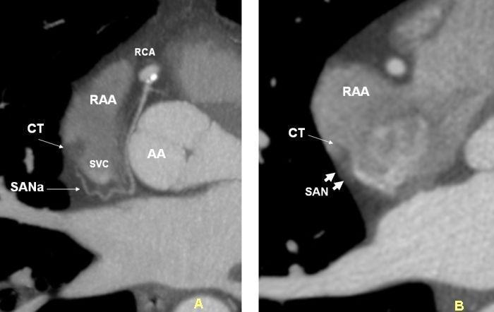
This diagnostic image consists of two axial Multi-Detector Computed Tomography (MDCT) scans (A and B) focusing on the cardiac anatomy of the right atrium and its conduction system.
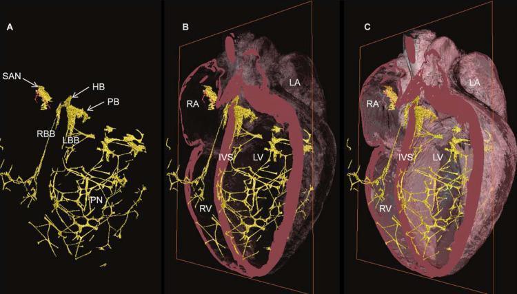
A 3D diagnostic anatomical reconstruction illustrating the Cardiac Conduction System (CCS) in a mammalian heart. The image is divided into three panels (A, B, C) showing varying levels of transparency of the myocardium. In Panel A, the CCS is isolated in yellow, highlighting major components: the Sinoatrial Node (SAN), His Bundle (HB), Penetrating Bundle (PB), Right Bundle Branch (RBB), Left Bundle Branch (LBB), and the extensive Purkinje Network (PN). Panels B and C overlay the yellow conduction network onto the pink myocardial mass with decreasing transparency. Key anatomical regions labeled include the Right Atrium (RA), Left Atrium (LA), Right Ventricle (RV), Left Ventricle (LV), and the Interventricular Septum (IVS). The visual emphasizes the distribution and density of conduction fibers throughout the heart, specifically showing how the bundle branches descend along the IVS before arborizing into a dense meshwork (Purkinje fibers) within the ventricular walls to facilitate coordinated contraction.
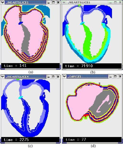
This composite image presents four panels (a–d) of computerized cardiac simulations focusing on stratified heart wall models and electrophysiological properties. Panel (a) shows a 2-D stratified heart model with multi-colored concentric layers representing the endocardium-to-epicardium transition in the ventricular walls. Panel (b) illustrates a 2-D simulation of epicardium-to-endocardium repolarization, with a color gradient (green to dark blue) mapped to transmembrane potential across the myocardium. Panel (c) highlights two areas of myocardial ischemia, visualized through variations in blue and cyan shades. Panel (d) displays a cross-sectional view of a 3-D stratified model, further demonstrating the arc-shaped fiber orientation and wall layering. The models utilize cellular automata to represent different cardiac tissues, including the sinoatrial node (SAN), atrioventricular node (AVN), and the conduction system (bundle branches and Purkinje fibers). These simulations are designed for medical education and research into arrhythmia generation, ischemia effects, and the electrical heterogeneity of the heart walls, particularly the simulation of M cells and transmural action potential duration gradients.
"sinoatrial node"[MeSH Terms] AND "pacemaker"
- Location: upper right atrium, near the opening of the superior vena cava.
- Role: it is the primary pacemaker because it depolarizes spontaneously (automaticity) faster than any other cardiac tissue. This sets the normal sinus rhythm of about 60-100 beats/min.
- Mechanism: pacemaker cells have an unstable resting potential. A slow diastolic depolarization, driven partly by the "funny" current (I_f, carried by HCN4 channels), brings the cell to threshold. Fuster and Hurst's The Heart cites HCN4 as central to human SA node pacemaker activity (15th Edition, "Normal Automaticity").
- Autonomic control: sympathetic stimulation raises the rate. Vagal (muscarinic M2) stimulation slows it. Sabiston describes the SA node as the primary node, influenced by sympathetic input (Sabiston Textbook of Surgery, "Cardiac Physiology"). Katzung describes acetylcholine acting on SA node M2 receptors (Katzung's Basic and Clinical Pharmacology, 16th Edition).
| Site | Approx. intrinsic rate |
|---|---|
| Sinoatrial node | 60-100/min |
| AV node / junction | 40-60/min |
| His-Purkinje / ventricles | 20-40/min |
- Artificial pacemaker: an implanted device that paces the heart when the SA node or conduction system fails, for example in sick sinus syndrome or heart block.
- Biological pacemaker: an experimental approach that uses gene transfer, such as TBX18, to create pacemaker activity (Fuster and Hurst's The Heart, "Biological Pacemakers").
- Ectopic pacemaker: any site other than the SA node that takes over rhythm control.
Artificial pacemaker medical term
chest radiograph permanent pacemaker leads right atrium right ventricle
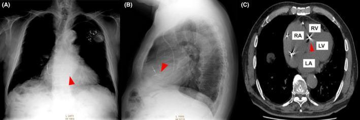
This composite clinical image presents a multimodal evaluation of a permanent pacemaker system. Panel A is a posteroanterior (PA) chest radiograph showing the cardiac silhouette, lungs, and the pacemaker generator in the left infraclavicular region with leads traversing the venous system. Panel B is a lateral chest radiograph providing a profile view of the lead trajectory. Panel C is an axial computed tomography (CT) scan through the heart. In all three panels, red arrowheads highlight the distal tip of the right ventricular (RV) lead. The CT scan (C) specifically provides high-resolution anatomical localization, with labels for the right atrium (RA), right ventricle (RV), left ventricle (LV), and left atrium (LA). It demonstrates the RV lead implanted at the basal interventricular septum, visualized as a high-density, radiopaque structure. This series illustrates the use of multi-planar imaging to confirm lead positioning and evaluate potential cardiac device complications or anatomical placement relative to the interventricular septum.
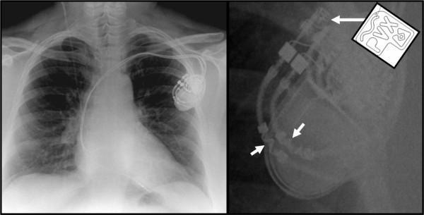
This composite diagnostic image features a posterior-anterior (PA) chest radiograph (left) and a magnified lateral-oblique view (right) of a dual-chamber permanent pacemaker. The primary radiograph shows the pacemaker pulse generator (can) implanted in the left infraclavicular region, with two radiopaque leads traversing the subclavian vein into the right atrium and right ventricle. The magnified image highlights key markers used to identify MRI-conditional (MRI-safe) status. A long white arrow points to a specific radiopaque wavy line and alphanumeric code ('PVX') on the device header, mirrored by a schematic inlay for clarity. Short white arrows indicate similar wavy radiopaque markers located on the proximal portion of the leads. These visual identifiers are critical for clinicians to verify that the implanted Cardiac Rhythm Management (CRM) device is compatible with magnetic resonance imaging environments, a standard feature in modern pacing systems used for patients requiring ongoing serial MRI monitoring.
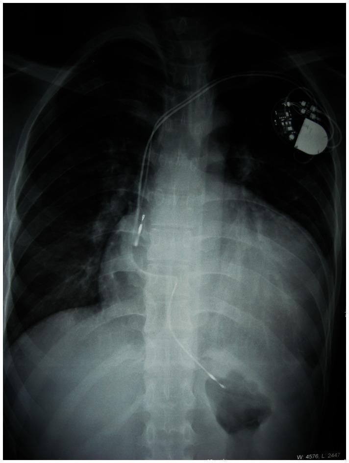
This diagnostic image is a postero-anterior (PA) chest radiograph demonstrating severe cardiomegaly and an implanted cardiac device. The cardiac silhouette is massively enlarged, exhibiting a cardiothoracic ratio (CTR) of approximately 70.6%, which is characteristic of advanced hypertrophic cardiomyopathy (HCM). A permanent dual-chamber pacemaker is visible in the left infraclavicular region (viewer's right). Two radiopaque leads originate from the generator; one lead terminates in the right atrium, and the second lead courses medially and inferiorly to terminate in the right ventricle. The lungs appear relatively clear, though the excessive cardiac volume significantly displaces the adjacent pulmonary structures. This radiograph serves as a clinical example of cardiac remodeling and secondary pacemaker implantation required for rhythm management in patients with complex cardiomyopathies and conduction system diseases, such as those associated with PRKAG2 mutations or Wolff-Parkinson-White syndrome.
"Pacemaker, Artificial"[MeSH Terms]
- Pulse generator: the battery and electronic circuitry for sensing and pacing.
- Lead system: wires that connect the generator to the electrodes and stimulate the myocardium.
| Type | Notes |
|---|---|
| Temporary: transcutaneous, transvenous, epicardial | Short-term use for emergencies or after cardiac surgery |
| Permanent single-chamber | One lead in the right atrium or right ventricle |
| Permanent dual-chamber | Leads in the right atrium and right ventricle |
| Biventricular (CRT-P) | Cardiac resynchronization therapy, for heart failure with dyssynchrony |
| Conduction system pacing | His bundle or left bundle branch area pacing |
| Leadless pacemaker | Self-contained device placed directly in the right ventricle |
| ICD | Implantable cardioverter-defibrillator, which has pacing and shock capability. It is not a pure pacemaker. |
- Symptomatic bradycardia from sick sinus syndrome (sinus node dysfunction)
- Second-degree Mobitz II or third-degree (complete) AV block
- Bradycardia with atrial fibrillation (slow ventricular response)
- Selected cases of heart failure (CRT)
- If a patient with a permanent pacemaker needs a defibrillation shock, place the pads or paddles at least 8 cm from the pulse generator (Tintinalli's Emergency Medicine, "Resuscitation in patients with a permanent pacemaker").
- Electromagnetic interference and invasive procedures near the device can cause malfunction, so perioperative management guidelines apply (Morgan and Mikhail's Clinical Anesthesiology, 7e, "Cardiac Conditions"; Miller's Anesthesia, 10e).
- Complications include infection, including pacemaker lead endocarditis (Fuster and Hurst's The Heart, references; ROSEN's Emergency Medicine, "Complications of Implantation").
- Leadless pacemakers (PMID 37961771)
- Long-term survival after pacemaker implantation following cardiac surgery (PMID 38657782)
- Pacemaker requirement predictors in unexplained syncope with a loop recorder (PMID 38402528)