
Explain me about working length in, uh, RCT and around text conservative. So, explain me about working length, define it and classify, classify the methods of working length determination and, uh, explain me about apex locators and, uh, explain me about ingles technique. I-N-G-L-E-S, ingles technique. And, uh... Mm. Enda. "What is a end of a operating material and techniques?" Um, "What is thermoplasticized cut upper shell technique?" Entendi. Explain event and why to do abdulating with canal. Materials used and explain me about lateral compaction technique. And... Measures of determination of broken length and electronic apex locator. And explain me about principles of shaping and cleaning of root canal and crown down preparations, advantages and disadvantages. Explain about crown down preparation also. And explain me about the significance of working length, methods of working length determination. Um... May explain me about this, some of these things.
working length determination endodontics Ingle's technique apex locator methods
crown down preparation endodontics principles shaping cleaning root canal obturation lateral compaction thermoplasticized gutta percha
electronic apex locator working length determination root canal
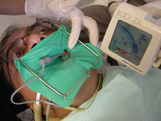
This clinical photograph captures a live endodontic procedure, demonstrating the use of an electronic apex locator (EAL) for working length determination. The patient is prepared with a green rubber dam isolation held by a metal Young frame, ensuring a sterile field. An endodontic hand file is inserted into the root canal of a treated tooth, with a clip connecting the file to the EAL via a lead wire. To the right of the patient's head, the 'Root ZX II' device (J. Morita Corp) is prominently displayed. The device's LCD screen shows a steady graphical bar on a curved scale, indicating the real-time position of the file tip relative to the apical foramen. A clinician's gloved hand is visible, managing the rubber dam setup. This image serves as an educational reference for endodontic isolation techniques, apical patency assessment, and the integration of electronic diagnostic tools in root canal therapy.
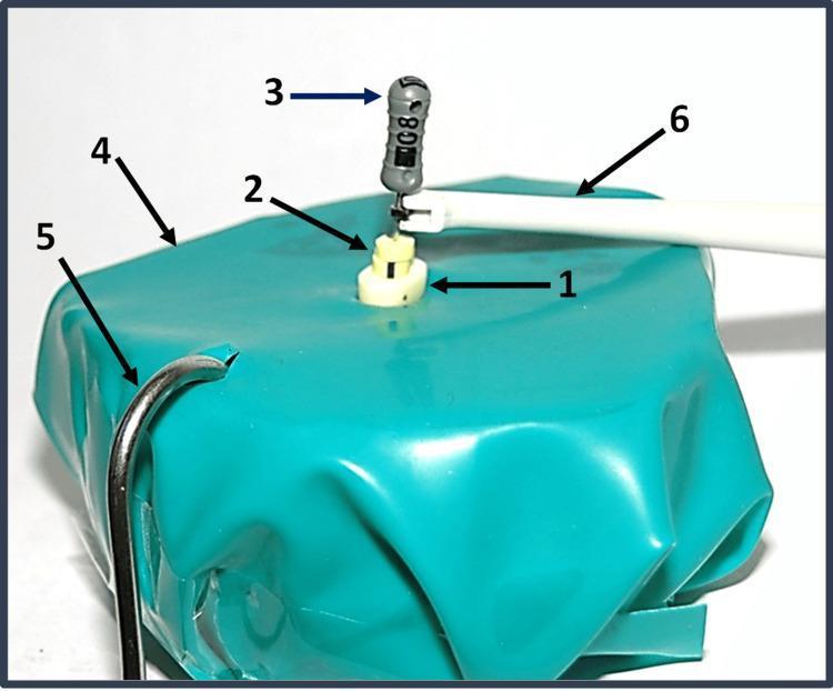
A clinical photograph of an in vitro endodontic experimental setup designed for electronic apex locator testing. The image shows a decoronated human premolar (1) embedded in a porous block saturated with Ringer’s solution to simulate clinical conductivity. A size 8 K-file (3) with a grey handle is inserted into the root canal system, featuring two light yellow cylindrical double stoppers (2) used as reference points for canal length measurement. The experimental model is draped with a turquoise rubber dam sheet (4). Integrated into the circuit are two essential electronic apex locator components: a metal lip clip (5) hooked into the dam and a white file clip (6) connected to the cervical aspect of the K-file. This setup demonstrates the procedural assembly for measuring actual versus electronic working length in a laboratory setting, simulating the electrical resistance of human periodontal tissues.
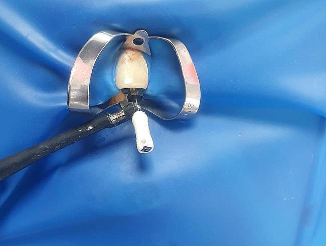
A clinical procedural photograph showing an endodontic setup for electronic apex localization. A single anterior tooth is isolated using a blue rubber dam and a stainless steel cervical clamp. The tooth crown is off-white with visible reddish-brown staining near the gingival margin. A K-file with a white handle (size 15) is inserted into the root canal access cavity. An electronic apex locator (EAL) electrode probe, featuring a black insulated wire and metal contact, is attached to the metal shaft of the K-file. This configuration is used to determine the working length of the root canal by measuring electrical impedance. The setup demonstrates standard isolation protocols to maintain a dry field and prevent contamination during endodontic therapy.
lateral compaction technique gutta percha root canal obturation spreader

This diagnostic radiographic image displays six dental X-rays organized in a 3x2 grid, illustrating the outcomes of three endodontic obturation techniques. Each technique is shown in two views: vestibule-lingual (left column) and mesiodistal (right column). Panels 1a and 1b demonstrate Cold Lateral Condensation, showing variable density and slight irregularities in the radiopacity of the root canal filling. Panels 2a and 2b depict the Continuous Wave technique, characterized by a highly homogenous and dense radiopaque filling with superior adaptation to the canal walls. Panels 3a and 3b illustrate a Hybrid Technique, showing balanced filling density and apical seal. The image serves as a comparative study in restorative dentistry, focusing on the homogeneity, apical extent, and wall adaptation of gutta-percha and sealer within the root canal system. Key educational concepts include endodontic compaction efficacy, radiographic evaluation of obturation quality, and anatomical adaptation of dental filling materials.
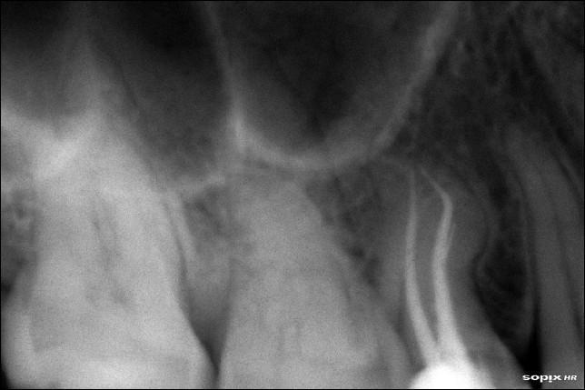
A periapical dental radiograph of the maxillary right posterior region, specifically showcasing a maxillary premolar post-endodontic treatment. The image demonstrates root canal obturation using radiopaque filling material (likely gutta-percha). Two distinct root canals (buccal and palatal) are visible, showing a complete, homogenous seal extending to the anatomical apices. The buccal canal exhibits a singular distal curvature, while the palatal canal shows a characteristic S-shaped or complex curvature that was successfully negotiated and filled. The surrounding alveolar bone shows a normal trabecular pattern with a well-defined lamina dura and no evidence of periapical radiolucency, indicating the absence of inflammatory lesions. The maxillary sinus floor is visible superior to the root apices. This diagnostic image serves as an educational example of successful complex root canal anatomy management and obturation using the lateral compaction technique.
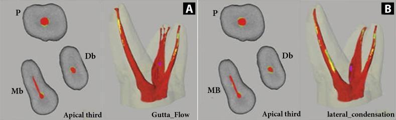
A diagnostic comparison of root canal obturation techniques using micro-computed tomography (micro-CT) imaging. The figure presents 2D cross-sections of the apical third (left) and 3D reconstructed models (right) for two methods: GuttaFlow (A) and Cold Lateral Condensation (B). The imaging employs a color-coded segmentation system to visualize canal filling quality: red represents Gutta-Percha (GP), yellow/green represents endodontic sealer, and violet indicates internal voids. In GuttaFlow (A), the GP exhibits a highly homogenous and continuous distribution throughout the canal system with minimal sealer interface and isolated micro-voids. In contrast, Cold Lateral Condensation (B) demonstrates a more heterogeneous filling pattern, characterized by larger areas of sealer (yellow/green) and a higher frequency of voids (violet) particularly along the canal walls. The 2D cross-sections (labeled P for Palatal, Db for Distobuccal, and Mb/MB for Mesiobuccal roots) further highlight the more centralized and dense GP core in the GuttaFlow group compared to the more irregular distribution in the lateral condensation group. This comparative analysis serves as an educational tool for endodontic specialists to evaluate obturation density and marginal adaptation.
Root Canal Treatment: A Comprehensive Guide
1. WORKING LENGTH - DEFINITION AND SIGNIFICANCE
Definition
- The minor foramen (apical constriction) is the narrowest part of the canal, located 0.5-0.75 mm coronal to the major foramen (apical foramen).
- The major foramen is 0.5 mm from the anatomical root tip.
- So working length = anatomic length minus approximately 1.0-1.5 mm.
Significance of Working Length
| Reason | Explanation |
|---|---|
| Prevents overinstrumentation | Avoids damage to periapical tissues, cementum, and PDL |
| Prevents underinstrumentation | Ensures complete debridement of the canal |
| Controls obturation level | Filling short of the apex causes treatment failure; overfilling causes periapical inflammation |
| Avoids ledge formation | Keeps files within the canal path |
| Prevents apical perforation | Especially in curved canals |
| Guides irrigant depth | Ensures irrigants reach the full canal length |
2. CLASSIFICATION OF METHODS FOR WORKING LENGTH DETERMINATION
A. Conventional / Traditional Methods
- Anatomical (Average Length) Method
- Tactile Sensation Method
- Radiographic Methods
- Ingle's method (most widely used)
- Weine's modification
- Grossman's method
- Apical Sensitivity / Pain Response Method (Dip test)
- Bleeding Point Method (paper points)
- Digital Tactile Sense
B. Electronic Method
- Electronic Apex Locators (EAL) - the modern standard
3. INGLE'S RADIOGRAPHIC TECHNIQUE (Most Important)
Step-by-Step Procedure
- Take a good quality preoperative periapical radiograph.
- Measure the tooth length from the stable occlusal/incisal reference point to the radiographic apex.
- Subtract 1 mm from this measurement:
- 0.5 mm for the apical constriction (minor foramen is short of the apex)
- 0.5 mm for radiographic image distortion
- This gives the Estimated Working Length (EWL).
- Transfer this EWL measurement to a diagnostic file (K-file #10 or #15) using a silicon rubber stop.
- Insert the file into the root canal to the EWL.
- Use paralleling technique (long cone/XCP technique preferred for accuracy).
- Take a periapical radiograph with the file in situ.
- On the radiograph, observe where the file tip is relative to the radiographic apex:
- 0.5 - 1.0 mm short of apex → Working length is ESTABLISHED - no adjustment needed
- More than 1.0 mm short of apex → Add the difference to EWL; readjust stop; retake radiograph
- Beyond the apex → Subtract the difference from EWL; readjust and retake
- Final working length is confirmed when the file tip is exactly 0.5-1.0 mm short of the radiographic apex.
Weine's Modifications to Ingle's Technique
- Periapical bone resorption present → Reduce WL to 1.5 mm short of radiographic apex (resorption destroys the apical constriction)
- Apical root resorption present → Reduce WL to 2.0 mm short of radiographic apex; create an artificial apical stop
Limitations of Radiographic Methods
- Only 2D representation of 3D structure
- Foreshortening/elongation errors
- Cannot differentiate anatomic apex from radiographic apex
- Multiple radiographs = radiation exposure
- Time-consuming
- Cannot detect canal curvature in buccolingual plane
4. ELECTRONIC APEX LOCATORS (EAL)
Principle
- A file clip attached to the endodontic file inside the canal
- A lip clip (reference electrode) attached to the patient's lip/oral mucosa
Generations of Apex Locators
| Generation | Principle | Examples | Drawback |
|---|---|---|---|
| 1st (Resistance-based) | Constant electrical resistance at apex = 6.5 kΩ | Sunada (1962) | Unreliable; affected by electrolytes in canal |
| 2nd (Impedance-based) | Single frequency impedance | Endocater | Same limitation - affected by canal contents |
| 3rd (Ratio/Frequency) | Ratio of impedance at two frequencies | Root ZX (J. Morita), Apit | Reliable even with fluid in canal |
| 4th (Multi-frequency) | Multiple frequencies analyzed | Elements Diagnostic, Propex | Highly accurate |
| 5th | Combination apex locator + pulp tester | Newer devices | Most advanced |
Root ZX (J. Morita) - Gold Standard EAL
How to Use an EAL (Clinical Technique)
- Place rubber dam and complete access cavity preparation.
- Attach lip clip to the patient's lip.
- Attach the file clip to a K-file (size #8 or #10).
- Insert file into the canal while watching the display.
- The display shows the file progressing toward the apex on a graphic scale.
- Stop when the display reads "APEX" or 0.0-0.5 on the scale (the apex position).
- Place a rubber stop at the reference point and measure = Working Length.
- Confirm with a radiograph (still recommended for medico-legal purposes).
Advantages of EAL
- No radiation exposure
- Real-time feedback
- Accurate (±0.5 mm)
- Useful in patients where radiographs are difficult (e.g., gag reflex, pregnancy)
- Works even with some fluid in canal (3rd/4th generation)
- Fast
Disadvantages of EAL
- Not accurate in:
- Open apex (immature teeth) - no apical constriction
- Presence of excessive bleeding or NaOCl flooding
- Root perforations
- Calcified canals
- Technique-sensitive
- Cannot replace radiograph entirely
5. PRINCIPLES OF SHAPING AND CLEANING OF ROOT CANALS
- Shape the canal continuously tapering from orifice to apex - funnel-shaped prep
- Maintain the original canal curvature - do not transport or straighten
- Keep the apical foramen as small as possible
- Keep the foramen in its original position - no apical transportation
- Clean/debride the entire canal - remove pulp, bacteria, debris
- Irrigate copiously - sodium hypochlorite (NaOCl) is the primary irrigant; EDTA for smear layer
- Create a continuous taper for 3D obturation
6. CROWN-DOWN PREPARATION (Marshall & Pappin, 1980)
Definition
Sequence
- Start at the coronal third with large files/rotary instruments.
- Progressively move toward the apex with smaller instruments.
- The final apical preparation is done last with the smallest instrument that reaches working length.
Why Crown-Down?
- Removes the bulk of debris and pulp before instruments reach the apex - prevents apical extrusion of debris
- Creates straight-line access to the apical third early
- Improves irrigant penetration to the full canal length
- Reduces likelihood of instrument separation in apical third
Advantages of Crown-Down Preparation
| Advantage | Explanation |
|---|---|
| Reduces apical extrusion | Debris pushed out before apical prep |
| Better irrigation | Coronal enlargement allows deeper irrigant penetration |
| Reduces ledging | Straight-line access achieved early |
| Reduces instrument separation | Less torque on apical instruments because coronal bulk is already removed |
| Better tactile control | File faces less resistance when apical area is reached |
| Maintains canal curvature | Less chance of transportation |
| Compatible with NiTi rotary systems | Most NiTi systems (ProTaper, WaveOne, etc.) use crown-down sequences |
Disadvantages of Crown-Down Preparation
| Disadvantage | Explanation |
|---|---|
| Risk of over-enlargement coronally | Excessive removal of coronal dentin can weaken root |
| Technique-sensitive | Requires careful step-by-step progression |
| More instruments required | Multiple sizes needed for the sequence |
| Timing | May take more time than step-back in simple canals |
| Strip perforation risk | In curved canals if coronal flaring is too aggressive |
7. OBTURATION OF THE ROOT CANAL
Why Obturate?
- Prevent reinfection by microorganisms from the oral environment
- Entomb remaining bacteria, depriving them of nutrients
- Seal lateral canals and accessory canals
- Provide a stable apical seal
- Prepare the tooth for coronal restoration
Ideal Properties of Obturating Material
- Biocompatible
- Dimensionally stable (no shrinkage)
- Easily placeable and removable (retreatment)
- Radiopaque
- Bacteriostatic
- Non-staining
- Good seal (hermetic)
Primary Obturating Material: Gutta-Percha (GP)
- Beta phase - solid at room temp, used in standardized and non-standardized cones, more stable
- Alpha phase - flows with heat/pressure, used in thermoplasticized systems
Sealer/Cement (Root Canal Sealer)
- Fill gaps between GP and canal walls
- Seal lateral canals
- Lubricate for cone placement
8. LATERAL COMPACTION (COLD LATERAL CONDENSATION) TECHNIQUE
Instruments Used
- Master cone (standardized GP point) - matches the final apical preparation size
- Metal spreader / finger spreader - used to compact the GP laterally
- Accessory / auxiliary cones - smaller GP cones placed in the spaces created by the spreader
Step-by-Step Technique
- Choose a standardized GP cone matching the final apical instrument size (e.g., if you finished with a size 25 file, use a #25 GP cone).
- Trim the tip slightly if needed for a snug fit at working length (tug-back).
- Verify fit radiographically.
- Coat the master cone or canal walls with sealer (mix per instructions).
- Some clinicians use a lentulo spiral to coat canal walls.
- Insert master cone to working length; confirm tug-back.
- Insert a metal spreader alongside the master cone, pressing laterally against the canal wall.
- Advance the spreader to within 1-2 mm of working length.
- Apply firm apical pressure, then rotate 90-180° and withdraw.
- Immediately place an accessory cone into the space created by the spreader.
- Repeat steps 4 and 5 until no spreader can penetrate more than 3-4 mm into the canal.
- Cut excess GP at the orifice with a heated plugger.
- Verify obturation with a radiograph.
Advantages of Lateral Compaction
- Simple technique, easy to learn
- Reproducible results
- Controlled and predictable
- Can be used for most canal shapes
- Low risk of overfilling
- Can be verified step by step
Disadvantages of Lateral Compaction
- Not ideal for irregular or C-shaped canals
- Voids may remain (sealer-filled spaces)
- Less homogeneous than warm techniques
- Spreader may crack roots (excessive lateral force)
- Does not fill lateral/accessory canals as well as warm techniques
9. THERMOPLASTICIZED GUTTA-PERCHA TECHNIQUES
Classification
| Category | Technique | Example Systems |
|---|---|---|
| Injectable thermoplasticized GP | GP heated outside and injected | Obtura II, Calamus, Elements Free |
| Carrier-based | GP-coated carrier inserted | Thermafil, SimpliFill |
| Warm vertical compaction | GP heated in-situ from coronal | Schilder technique, Continuous Wave |
| Thermomechanical compaction | Rotating compactor generates heat | McSpadden compactor |
Warm Vertical Compaction (Schilder Technique)
- Master cone placed to WL.
- Heat is applied to the coronal portion using a heat carrier.
- Warm pluggers compact the softened GP in vertical (apical) direction.
- Successive waves of plasticization and compaction fill the canal.
- Lateral canals and fins are better filled than with cold lateral technique.
Thermafil (Carrier-Based System)
- The canal is sized and a Thermafil verifier is used to select the correct size.
- The appropriate Thermafil carrier (plastic core coated with alpha-phase GP) is heated in the oven.
- Carrier is inserted to full working length in one motion.
- The handle is cut off; the plastic core remains in the canal as part of the fill.
Obtura II (Injectable System)
- GP pellets loaded into a heated gun (temperature ~160-200°C).
- The needle tip placed 4-5 mm from the apex.
- Thermoplasticized GP injected while slowly withdrawing.
- Often combined with lateral compaction for apical 4-5 mm, then injectable GP for coronal fill (hybrid technique).
Advantages of Thermoplasticized Techniques
- Better 3D fill - fills lateral canals, fins, anastomoses
- More homogeneous mass
- Less sealer required
- Superior for complex canal anatomy (C-shaped, oval canals)
Disadvantages
- Risk of overfilling (GP flows beyond apex)
- More technique-sensitive
- Requires special equipment
- Carrier-based systems can be difficult to remove during retreatment
- GP contraction on cooling must be compensated with vertical pressure
10. METHODS SUMMARY: WORKING LENGTH DETERMINATION
| Method | Description | Accuracy |
|---|---|---|
| Average anatomy tables | Use known average tooth lengths as starting estimate | Low (only for EWL) |
| Apical sensitivity | Patient reports pain when file exits foramen | Unreliable; requires vital pulp |
| Tactile sensation | Operator feels file slip through foramen | Unreliable; technique-dependent |
| Bleeding/paper point | Paper point shows blood only at apical level | Approximate |
| Ingle's radiographic | File in canal + periapical X-ray + measurement | Good; most traditional |
| Electronic apex locator | Electrical impedance/ratio measurement | Excellent; ±0.5 mm |
| Combined (EAL + X-ray) | EAL for working length + radiograph for confirmation | Best overall |
Quick Summary Table
| Topic | Key Point |
|---|---|
| Working length | Distance from reference point to apical constriction (0.5-1 mm short of radiographic apex) |
| Ingle's technique | Measure from X-ray, subtract 1 mm, adjust with diagnostic file, confirm radiographically |
| EAL principle | Electrical resistance/impedance; Root ZX uses ratio of two frequencies |
| Crown-down | Instrument from crown toward apex (large to small); reduces debris extrusion |
| Lateral compaction | Master cone + spreader + accessory cones; gold standard technique |
| Thermoplasticized GP | Heat-softened GP for better 3D fill; Thermafil, Obtura, warm vertical methods |
| Why obturate | Seal canal, prevent reinfection, entomb bacteria, provide coronal seal |
- Ingle's Radiographic Method - Dentowesome - steps and Weine's modifications
- Pocket Dentistry - EAL and WL Measurement - classification of WL methods
- PMC in vivo EAL accuracy study - EAL clinical accuracy
- ScienceDirect - Root Canal Obturation Overview - lateral compaction, thermoplasticized techniques
- Ecronicon - New Obturation Techniques Review - Obtura, Thermafil, compaction methods
- Oral Health Group - Principle-Driven Crown Down - crown-down principles
- Grossman's Endodontic Practice, 13th edition