
What is angle of Weiburg in... Um, angles of hip joint, what is its significance? What does it do?
Wiberg center edge angle hip joint acetabular coverage diagram
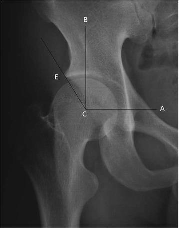
This diagnostic image is an anteroposterior (AP) X-ray radiograph of a human hip joint, illustrating the methodology for measuring the center-edge (CE) angle, also known as the Wiberg angle. The anatomical structures shown include the pelvic acetabulum and the proximal femoral head. Superimposed on the radiograph are three geometric reference lines originating from point 'C', representing the geometric center of the femoral head. Line C-A extends horizontally toward the contralateral hip center as a reference baseline. Line C-B is a vertical line drawn perpendicular to C-A through point C. Line C-E is drawn from the center of the femoral head to the most lateral margin of the acetabular roof (point E). The CE angle is defined as the angle formed between the vertical line C-B and the oblique line C-E. Clinically, this measurement is essential for orthopedic assessment of acetabular coverage. It is used to diagnose and quantify conditions such as hip dysplasia (reduced CE angle) or pincer-type femoroacetabular impingement (increased CE angle), assisting in surgical planning and postoperative follow-up.
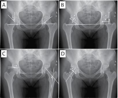
This composite of four pelvic anteroposterior (AP) radiographs (labeled A-D) illustrates standard orthopedic measurements used to evaluate hip joint morphology, specifically for diagnosing hip dysplasia and femoroacetabular impingement (FAI). Panel A demonstrates Wiberg's center-edge (CE) angle, calculated from the center of the femoral head to the lateral acetabular rim against a vertical reference, and Sharp's angle, measuring acetabular inclination using the horizontal teardrop line. Panel B displays the acetabular depth-to-width ratio and the femoral head extrusion index (a:b ratio), quantifying the degree of femoral head coverage by the acetabulum. Panel C depicts the acetabular roof obliquity angle (Tonnis angle) and the caput-collum-diaphyseal (CCD) angle, which assesses the alignment between the femoral shaft and neck. Panel D illustrates Murray's femoral head ratio, focusing on the femoral head's position relative to the neck axis. Key anatomical landmarks identified include the femoral heads, acetabular rims, iliac wings, teardrop lines, and greater/lesser trochanters. These quantitative parameters are essential for evaluating joint stability, coverage, and proximal femoral geometry in clinical radiology and orthopedics.
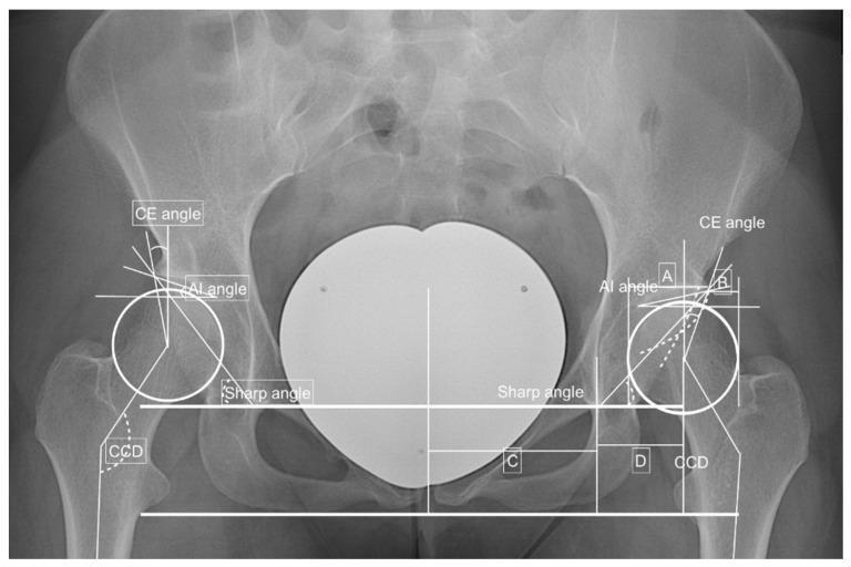
Anteroposterior (AP) pelvic radiograph demonstrating quantitative measurements for assessing hip joint morphology and Developmental Dysplasia of the Hip (DDH). The diagnostic image features bilateral annotations of key orthopedic angles: the Center-Edge (CE) angle (Wiberg's angle) for acetabular coverage, the Acetabular Index (AI) angle for the slope of the acetabular roof (Hilgenreiner’s line), and the Sharp angle for overall acetabular inclination. Additionally, the Caput-Collum-Diaphyseal (CCD) angle is marked to evaluate femoral neck-shaft alignment. Reference lines, including the Perkin line and teardrop lines, are overlaid to facilitate the calculation of the hip lateralization index and anterior hip index. The presence of a 'crossing over sign' is indicated, suggesting acetabular retroversion or anterior overcoverage. This educational visual is designed for orthopedic and radiological assessment of hip stability, impingement (FAI), and dysplastic variations, providing a clear protocol for preoperative planning or diagnostic evaluation of coxarthrosis risk factors.
Center-Edge Angle of Wiberg (CE Angle)
What it is
How it is measured
- First, identify point C - the geometric center of the femoral head (using a best-fit circle)
- Draw line C-B: a vertical line through C, perpendicular to the pelvic horizontal (interischial/transverse) line
- Draw line C-E: a line from C to the lateral margin of the acetabular roof
- The angle between C-B and C-E is the CE angle
Normal Values
| Category | CE Angle |
|---|---|
| Normal (adult) | 25° to 40° |
| Borderline dysplasia | 20° to 25° |
| Dysplastic hip | < 20° |
| Overcoverage / Pincer-type FAI | > 40° |
- Should not be less than 10° between 1-4 years of age
- Should be in the range of 15-20° at 5 years of age
Clinical Significance
1. Low CE angle (< 20°) - Hip Dysplasia
- Indicates undercoverage - the acetabulum is too shallow or too vertically oriented
- The femoral head sits laterally, with poor containment
- The labrum is forced to act as part of the weight-bearing surface, making it prone to labral tears
- Associated with valgus femoral neck and acetabular anteversion/retroversion
- Predisposes to early osteoarthritis - recognized as a precursor of OA in 20-40% of hip OA patients
- Guides surgical planning - periacetabular osteotomy (PAO) aims to restore the CE angle to approximately 30-35°
2. High CE angle (> 40°) - Pincer-type FAI
- Indicates overcoverage - the acetabulum over-covers the femoral head
- Leads to repetitive abutment (impingement) between the acetabular rim and the proximal femur during terminal flexion and internal rotation
- Damages the labrum and causes articular cartilage delamination at the acetabular rim
Companion Measurement: Anterior CE Angle
Summary Table
| Finding | Interpretation |
|---|---|
| CE angle < 20° | Hip dysplasia, undercoverage, instability, OA risk |
| CE angle 20-25° | Borderline dysplastic |
| CE angle 25-40° | Normal |
| CE angle > 40° | Overcoverage, pincer FAI, impingement risk |