
Anaesthesia technology
Reading File
The query "Anaesthesia technology" is broad - it could cover many subtopics. Let me clarify before diving deep.
Asking for Preferences
What aspect of anaesthesia technology are you interested in? · What level of detail do you need?
Searching the medical library for anaesthesia machine and equipment content...
Finding Sources
Finding Sources
Searching the Web
anaesthesia machine components mechanisms 2024
Finding Sources
Finding Sources
Finding Sources
Finding Sources
Finding Sources
Excellent - I found three major anesthesia textbooks. Let me pull the key content on the anaesthesia machine from Miller's and Barash.
Finding Sources
Finding Sources
Reading File
Reading File
Reading File
Reading File
Reading File
Reading File
Reading File
Reading File
Reading File
Reading File
Reading File
Loading Image
I now have rich, detailed content from Miller's Anesthesia (10e) and Barash's Clinical Anesthesia (9e) to write a comprehensive, in-depth response. Let me compile everything.
Anaesthesia Machine & Equipment - In-Depth Guide
Sources: Miller's Anesthesia 10e, Barash's Clinical Anesthesia 9e, Morgan & Mikhail's Clinical Anesthesiology 7e
Overview
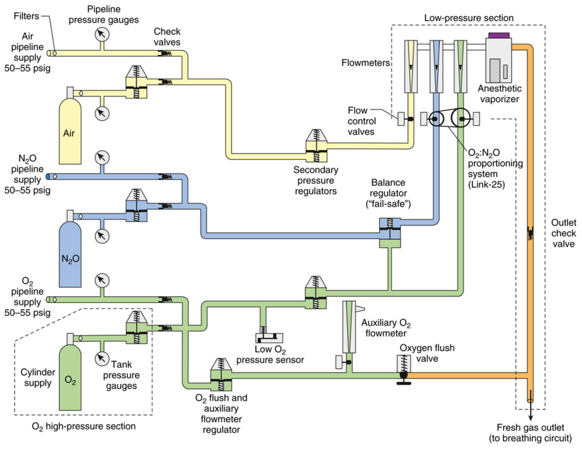
The anaesthesia workstation is fundamentally a pneumatic device - even modern, electronically controlled machines. Its core function is to receive breathing gases from supply sources, measure and mix them, enrich the mixture with anaesthetic vapour, and deliver that mixture to the patient's breathing circuit. The entire gas supply system can be divided into three pressure sections:
| Section | Pressure | Components |
|---|---|---|
| High-pressure | ~2000 psig (O₂), ~745 psig (N₂O) | E-cylinders, hanger yokes |
| Intermediate-pressure | 50-55 psig | Pipeline inlets, second-stage regulators, fail-safe valves, flowmeter controls |
| Low-pressure | Below flow control valves | Flowmeters, vaporizer, fresh gas outlet |
Here is the complete schematic of the GE Aespire workstation gas supply system:
1. Gas Supply System
1a. High-Pressure Section - E-Cylinders
The high-pressure section is normally inactive because the hospital central pipeline is the primary supply. E-cylinders serve as backup.
Hanger Yoke Assembly - each cylinder is mounted via a yoke that:
- Orients and supports the cylinder
- Provides a gas-tight seal via a Bodok washer
- Ensures unidirectional gas flow into the machine
- Contains the Pin Index Safety System (PISS) - a key safety feature where two metal pins on the yoke project into precisely corresponding holes on the cylinder valve assembly, unique to each gas. This prevents connecting the wrong gas cylinder.
High-pressure regulator - reduces variable cylinder pressure to a constant ~40-45 psig (deliberately lower than pipeline pressure of 50-55 psig). This is a critical safety design: if both cylinder and pipeline are open, the machine draws gas from the pipeline first, preserving the cylinder backup. - Barash's Clinical Anesthesia 9e, p. 1932
Important clinical point: If pipeline contamination (e.g. N₂O in the O₂ pipeline) occurs, simply opening the backup O₂ cylinder will NOT correct the situation if pipeline pressure remains above 40-45 psig. The machine must be physically disconnected from the pipeline for backup O₂ to flow. - Miller's Anesthesia 10e, p. 2232
Cylinder check valve - a one-way valve preventing backflow of machine gas out through an empty yoke or back into an empty cylinder.
1b. Intermediate-Pressure Section
The intermediate-pressure circuit (50-55 psig) runs from pipeline inlets or regulated cylinder output to the flow control valves. Key components include:
Fail-safe valve (Oxygen Failure Cutoff Valve) - located downstream from the N₂O supply. Shuts off or proportionally decreases N₂O flow if oxygen supply pressure drops. A high-priority alarm triggers when O₂ supply pressure falls below ~30 psig. This device protects against delivery of a hypoxic mixture, but it responds only to oxygen pressure, not oxygen concentration. - Barash's, p. 1933
Second-stage pressure regulators (O₂) - some GE machines reduce O₂ pipeline pressure to a precise 14 psig before the flow control valve, ensuring constant O₂ flow regardless of fluctuating pipeline pressures.
Oxygen flush valve - bypasses the flowmeters and vaporizer, delivering pure O₂ at 35-75 L/min directly to the low-pressure circuit. Because it bypasses the vaporizer, activating it during an anaesthetic dilutes the anaesthetic agent and can cause patient awareness. It can also cause barotrauma if the APL valve is closed during manual ventilation.
2. Flowmeters (Rotameters)
The classic flowmeter is a variable orifice, variable area device. The indicator float hovers freely inside a tapered glass flow tube where upward gas pressure forces exactly balance the downward gravitational pull.
Mechanism:
- The flow tube is tapered, widest at the top and narrowest at the bottom
- As the operator increases flow (opens the needle valve), upward pressure on the float increases - the float rises
- As the float rises in the tapered tube, the annular space (clearance between float and tube wall) increases, giving gas more room to pass - until upward and downward forces re-equalize
- The float's height directly reads the flow rate on a calibrated scale
Low vs. high flow dynamics:
- At low flows - the annular space is narrow and tubular (diameter < length). Flow is laminar, governed by gas viscosity
- At high flows - the annular space widens into an orifice shape (length < diameter). Flow is turbulent, governed by gas density
This is why flowmeters are gas-specific - calibrated for a particular gas's viscosity and density.
Safety features of flow control valves:
- The oxygen knob is larger, octagonal, and protrudes further than other knobs - distinguishable by touch alone
- Oxygen flow is positioned last in the bank (downstream), so if a leak occurs in any other flowmeter, it is the leaked gas (not O₂) that is lost
- Valve stops prevent excessive clockwise rotation that could damage the needle valve and seat
Electronic gas flow control - modern workstations (e.g. Dräger Apollo, GE Avance) use touchscreen interfaces. The operator sets a target flow; electronic proportional control valves and mass flow sensors manage delivery. The underlying pneumatic principles remain the same.
Proportioning systems (Hypoxic guards):
Two main designs prevent delivery of a hypoxic N₂O/O₂ mixture:
| System | Machine | Mechanism |
|---|---|---|
| Link-25 (GE) | GE Healthcare | Sprocket-and-chain mechanical linkage between N₂O and O₂ flow control knobs; ensures minimum 25% O₂ |
| S-ORC (Sensitive Oxygen Ratio Controller) | Dräger (Fabius, Apollo) | Pneumatic interlock using back-pressures from O₂ and N₂O flowmeters to modulate a slave N₂O control valve; cuts N₂O completely if O₂ flow < 200 mL/min |
3. Vaporizers
Physics of Vaporization
Saturated vapour pressure (SVP) - at any given temperature, a volatile liquid generates a characteristic vapour pressure. For sevoflurane at 20°C, SVP ≈ 157 mmHg. This is temperature-dependent: as temperature rises, SVP rises.
Latent heat of vaporization - vaporization requires energy. Without an external heat source, the remaining liquid cools as it evaporates, dropping SVP and reducing vaporizer output. Vaporizer design must compensate for this.
Boiling point - the temperature at which SVP equals atmospheric pressure. Desflurane's extremely low boiling point (22.8°C, close to room temperature) makes it impractical for conventional vaporizer designs.
Variable Bypass Vaporizers (e.g. Tec 5, Tec 7, Drager Vapor 2000)
Used for sevoflurane, isoflurane, halothane.
Mechanism:
- Incoming fresh gas flow splits at the vaporizer inlet into two streams:
- A bypass stream that passes around the vaporizing chamber (unaffected)
- A carrier gas stream that enters the vaporizing chamber, picks up saturated vapour, and exits
- The two streams recombine at the vaporizer outlet
- The concentration dial adjusts the ratio of bypass to carrier gas flow - rotating the dial to a higher concentration reduces bypass flow and increases the carrier gas fraction
Temperature compensation - the key engineering challenge. As the liquid agent cools from evaporation, SVP drops, threatening to reduce output below the dialled setting. Variable bypass vaporizers use a bimetallic strip (wax/metal element) in the bypass channel that expands with cooling, automatically restricting bypass flow and directing more gas through the vaporizing chamber to maintain constant output.
Hazards:
- Tipping - if a variable bypass vaporizer is tipped, liquid agent floods the bypass chamber and can deliver a dangerously high, potentially lethal concentration. Most manufacturers specify a post-tipping flush protocol and consultation of the user manual before returning to service
- Overfilling - if liquid enters the bypass chamber via overfilling (particularly if rocked/tipped during filling), excessive vapour concentrations result. Side-fill designs mitigate this
- Leaks - vaporizer filler caps, drain valves, or the vaporizer-manifold interface are common leak sources; may manifest as lower than expected inhaled agent concentration or agent odour
- Contamination - bacterial growth has been reported in sevoflurane vaporizers where water accumulation occurred
Desflurane Vaporizer (Tec 6 / D-Vapor)
Because desflurane boils at ~22.8°C, it cannot be used in a variable bypass vaporizer - it would spontaneously boil at room temperature, making temperature compensation impossible. The solution is an electrically heated, pressurized vaporizer:
- Desflurane reservoir is heated to 39°C, generating a reservoir vapour pressure of ~1500 mmHg (approximately 2 atmospheres gauge)
- A pressure-regulating valve controls vapour flow from the heated sump into the fresh gas stream
- The dial setting changes the size of a restrictor (R2), controlling how much vapour mixes with the fresh gas. Because the working pressure upstream is proportional to FGF, output concentration remains stable across a range of FGFs
- At FGF 1 L/min → working pressure = ~7.4 mmHg; at 10 L/min → ~74 mmHg; a linear relationship
Aladin Cassette Vaporizer (GE Aisys, Carestation)
The GE Aladin system uses interchangeable, agent-specific cassettes inserted into the workstation. An electronic control system measures the vapour pressure from the cassette and adjusts fresh gas split using a computer-controlled valve. This eliminates the need for manual temperature compensation.
Vaporizer Interlock System
On machines with multiple vaporizer mounting positions, a mechanical interlock prevents two vaporizers from being turned on simultaneously, avoiding agent mixing.
4. Anaesthesia Breathing Systems
The Circle System
The most common breathing system in modern anaesthesia. It is semi-closed or closed and allows CO₂ absorption to enable gas rebreathing - saving volatile agents and reducing theatre pollution.
Essential components:
- Fresh gas inlet
- Inspiratory unidirectional valve (opens during inhalation only)
- Inspiratory limb - corrugated tubing to patient
- Y-piece connecting to patient
- Expiratory limb - corrugated tubing from patient
- Expiratory unidirectional valve (opens during exhalation only)
- CO₂ absorber canister (soda lime or similar)
- Reservoir bag / APL (Adjustable Pressure-Limiting) valve
- Optional: ventilator connection
CO₂ Absorbents:
- Traditional soda lime = Ca(OH)₂ + NaOH + KOH + silica + indicator dye
- CO₂ absorption: CO₂ + H₂O → H₂CO₃; H₂CO₃ + 2NaOH → Na₂CO₃ + 2H₂O; Na₂CO₃ + Ca(OH)₂ → CaCO₃ + 2NaOH
- Colour indicator changes (e.g. white → violet in Medisorb; blue → white in Drägersorb) when absorbent is exhausted
- Critical hazard: desiccated soda lime (Baralyme formulation, now discontinued) interacting with sevoflurane caused fires inside breathing circuits; desiccated strong-base absorbents can produce carbon monoxide from desflurane/isoflurane, and Compound A (a nephrotoxic olefin) from sevoflurane - Barash's, p. 2003
Circle system hazards:
- Unidirectional valve stuck open → rebreathing, hypercapnia
- Unidirectional valve stuck closed → total circuit occlusion
- Expiratory valve stuck closed → breath stacking, barotrauma, tension pneumothorax
- Breathing circuit misconnections/disconnections = most common equipment-related adverse event (25 of 72 malpractice claims in one ASA closed claims analysis)
Coaxial circuits (e.g. Bain circuit variant) - "tube within a tube" where the inner tube carries fresh gas (inspiratory) and the outer tube carries exhaled gas (expiratory). This reduces circuit clutter and improves heat/moisture conservation, but inner tube kinking can mimic bronchospasm.
Mapleson Circuits
Non-rebreathing circuits that use no CO₂ absorber. Fresh gas flow (FGF) flushes exhaled CO₂ away. Different configurations (A, B, C, D, E, F) differ in where fresh gas enters and where the APL valve/reservoir is placed.
- Mapleson A (Magill) - most efficient for spontaneous ventilation (FGF = minute ventilation)
- Mapleson D/F - most efficient for controlled ventilation
- Jackson-Rees modification of Mapleson F - widely used in paediatrics
5. Anaesthesia Ventilators
Pneumatically Driven Bellows
Traditional design: a bellows housed in a chamber. Driving gas (O₂ or compressed air) pressurizes the chamber surrounding the bellows, compressing it and pushing gas to the patient. Expired gas refills the bellows.
- Ascending (standing) bellows - fill from bottom up; preferred because if a leak develops, the bellows collapses (visible warning)
- Descending bellows - fill by gravity; may continue to cycle even if disconnected from the patient (misleading; associated with undetected disconnection events)
Electric Piston Pump Ventilators
A piston inside a cylinder directly compresses gas to the patient. Advantages: no driving gas consumed, precise tidal volume delivery, better performance at low flows. Used in machines like older Dräger models.
Electric Turbine Ventilators
A turbine (impeller) generates gas flow. Found in modern workstations (Dräger Apollo, GE Carestation). Advantages: very fast response, high flexibility in ventilatory modes (pressure control, volume control, pressure support, SIMV, and more), no bellows to rupture.
Volume Reflector
Some GE machines use a "volume reflector" - a compliance compensation mechanism that adjusts delivered volume to account for compression losses in the circuit, improving tidal volume accuracy especially at low compliance.
6. Waste Gas Scavenging Systems (WGSS)
Trace anaesthetic gases are an occupational hazard. NIOSH limits for halogenated agents (without N₂O) are ≤2 ppm; with N₂O ≤0.5 ppm (halogenated) and ≤25 ppm (N₂O alone).
Components:
- Gas-collecting assembly - attached to the APL valve and ventilator pressure relief valve
- Transfer tubing - conveys waste gases from collection point
- Interface - regulates pressure between the breathing system and disposal system
- Open interface (passive/active) - communicates with atmosphere, no pressure buildup risk
- Closed interface - contains pressure relief valves (positive and negative) to prevent both excessive positive pressure (barotrauma) and negative pressure (rebreathing) being transmitted to the patient circuit
- Gas disposal system - either active (vacuum-driven hospital waste gas disposal system) or passive (ducted directly to outside)
7. Safety Features of the Modern Workstation
| Safety Feature | Function |
|---|---|
| Pin Index Safety System (PISS) | Prevents wrong gas cylinder connection |
| Diameter Index Safety System (DISS) | Prevents wrong pipeline connection |
| Colour coding | Gas-specific colours (O₂ = white UK/EU, green USA; N₂O = blue; Air = black/white) |
| Fail-safe/O₂ failure cutoff valve | Shuts N₂O if O₂ pressure drops |
| O₂:N₂O proportioning (Link-25/S-ORC) | Prevents hypoxic mixture delivery |
| O₂ flush valve | Emergency O₂ bypass |
| Oxygen analyser | Continuous FiO₂ monitoring |
| Airway pressure monitor | Alarm for disconnection or obstruction |
| Ascending bellows | Visible leak indicator |
| Vaporizer interlock | Prevents simultaneous agent delivery |
| Workstation self-tests | Automated pre-use checkout |
8. Pre-Use Checkout
The FDA 1993 anaesthesia apparatus checkout (and updated 2008 ASA/APSF-recommended checks) include:
- Verify auxiliary O₂ cylinder and self-inflating manual resuscitator available
- Turn on workstation and all monitors
- Calibrate O₂ analyser
- Verify low-pressure circuit integrity (vaporizer leak test)
- Verify breathing system integrity (circle system leak test)
- Test APL valve and scavenging
- Test flow control valves and unidirectional valves
- Test ventilator and confirm settings
- Test O₂ flush valve
- Workstation self-test (where applicable) - documented and signed - Barash's, p. 1924
Summary Diagram
The anaesthesia machine can be thought of as a gas pipeline with five functional stages:
SUPPLY → REGULATE → MEASURE → VAPORIZE → DELIVER
(cylinders/  (pressure   (flowmeters/ (vaporizer)  (breathing
 pipeline)   regulators)  electronic                circuit +
                          controls)                 ventilator)
Each stage has dedicated safety mechanisms layered in so that a single failure at any point is unlikely to reach the patient undetected.
Primary references:
- Miller's Anesthesia, 10e (Elsevier, 2023) - Chapter 20: The Anesthesia Workstation
- Barash's Clinical Anesthesia, 9e (Wolters Kluwer, 2022) - Chapter 25: The Anatomy of an Anesthesia Workstation
- Morgan & Mikhail's Clinical Anesthesiology, 7e - Chapter on Anaesthesia Equipment
This is a shared conversation. Sign in to Orris to start your own chat.