
DCP PLATE
- Design: A stainless steel or titanium plate with oval/elongated holes that allow controlled axial compression across a fracture site
- Mechanism: The screw head slides along the inclined portion of the hole, generating compression as it is tightened
- Uses: Diaphyseal fractures of long bones (femur, tibia, humerus, radius, ulna), non-unions, osteotomies
- Variants: Standard DCP, LC-DCP (Limited Contact), LCP (Locking Compression Plate)
DCP dynamic compression plate orthopedic fracture fixation
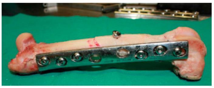
This clinical photograph displays an ex vivo femoral shaft undergoing internal fixation for a simple oblique fracture, serving as an educational example of orthopedic osteosynthesis. The primary stabilization is achieved using a shiny, metallic 8-hole Dynamic Compression Plate (DCP) contoured to the lateral aspect of the bone. The plate is secured with six bicortical screws positioned across the proximal and distal segments, acting in a neutralization function. Notably, an independent lag screw is placed perpendicularly across the fracture line to provide dynamic compression and enhance mechanical stability. The bone specimen exhibits a smooth cortical surface with visible reddish staining near the epiphyses, indicating the presence of vascularized tissue or residual soft matter. The arrangement demonstrates key principles of fracture management, including anatomical reduction and stable internal fixation to facilitate secondary bone healing. This image is relevant for surgical training and biomechanical study of plate-and-screw constructs in long bone fractures.
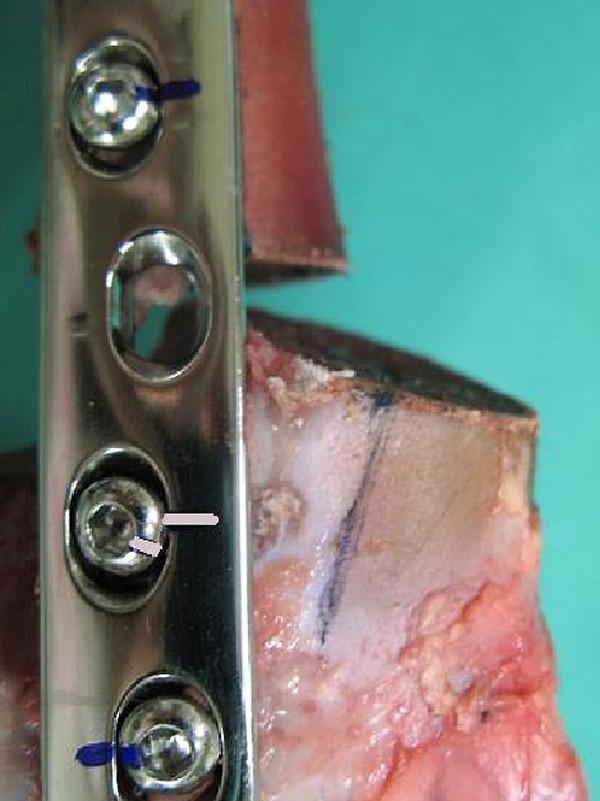
This clinical photograph displays a close-up of a Limited Contact Dynamic Compression Plate (LC-DCP) construct used in an orthopedic biomechanical study of femoral fracture fixation. The image illustrates a procedural failure analysis of an internal fixation system. A significant osteotomy gap is visible between the proximal and distal bone segments, showing asymmetrical widening at the cranial aspect and narrowing at the caudal aspect, indicating a cranial tilt and rotational displacement of the distal fragment. Metal screws are numbered for testing, with screw No. 5 specifically highlighting mechanical failure. The black marker lines on the screw head and the plate surface, which were originally aligned, show a clear deviation. This misalignment serves as visual confirmation of screw loosening and rotation within the plate hole during axial loading. The image is used to demonstrate the structural weakness of bone-plate constructs under compression and to identify signs of hardware migration in orthopedic surgery.
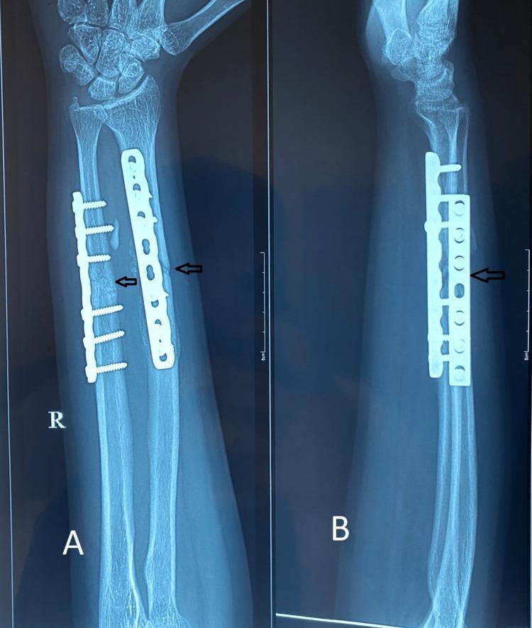
This diagnostic image consists of two radiographic views (anteroposterior, A; lateral, B) of a right forearm, three months post-operative. The radiographs demonstrate surgical internal fixation of both the radius and ulna using metallic compression plates and screws. A dynamic compression plate (DCP) is visible on the distal-to-mid shaft of the radius, secured with five cortical screws. A similar, shorter plate is affixed to the ulna, secured with five screws. Black arrows indicate the primary fracture sites on both bones. These sites show evidence of progressive fracture union characterized by bridging callus formation and increased radio-opacity, indicating biological consolidation. The surrounding soft tissues appear unremarkable, and the alignment of the radial and ulnar shafts is well-maintained. This image is an educational example of orthopedic fracture management using open reduction and internal fixation (ORIF) and the assessment of secondary bone healing in a clinical follow-up setting.
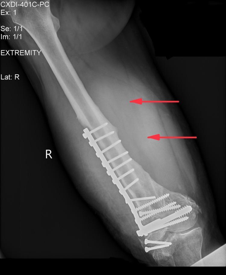
An anteroposterior (AP) view X-ray of the right distal femur demonstrating internal fixation and surrounding pathology. A radiopaque dynamic compression plate (DCP) is visible on the lateral aspect of the femoral shaft, secured by multiple orthopedic screws. In the adjacent soft tissues, there is a large, ill-defined area of increased radiolucency (hyperlucency) indicated by two red horizontal arrows, suggesting a significant soft tissue mass, fluid collection, or abscess. The distal femur shows signs of previous fracture healing or remodeling around the hardware. This diagnostic image is significant for evaluating post-surgical complications, such as infection or tumor formation (e.g., plasmablastic lymphoma as suggested by context) in the setting of chronic orthopedic implants.
DCP dynamic compression plate orthopedic fracture fixation design mechanism
Dynamic Compression Plate (DCP)
What Is It?
Design and Structure
| Feature | Detail |
|---|---|
| Material | Stainless steel or titanium alloy |
| Holes | Oval/elongated with a sloped, inclined floor (the Dynamic Compression Unit) |
| Screw size | 4.5 mm (large fragment) or 3.5 mm (small fragment) |
| Underside (DCP) | Broad, flat contact with bone surface |
| Underside (LC-DCP) | Scalloped/undercut - reduces periosteal contact |
Compression Mechanism - How It Works
- The screw hole has an inclined cylindrical ramp on one side
- When a screw is inserted eccentrically (off-center, away from the fracture), its rounded head engages the slope
- As the screw is tightened, it slides down and toward the fracture - displacing the bone fragment axially
- This generates interfragmentary compression (up to ~1 mm of translation per hole)
Screw Positions in DCP Holes
| Position | Drill Guide | Effect |
|---|---|---|
| Neutral | Guide depressed (upper part projects) | Screw holds without generating compression |
| Compression | Guide NOT depressed (flush) | Screw slides along ramp -> compresses fracture |
| Buttress | Special LC-DCP position | Resists shear forces |
| Inclined (lag screw) | Guide adjacent to fracture, depressed + angled | Allows lag screw through plate |
Plate Variants
| Plate | Key Difference | Best Use |
|---|---|---|
| DCP | Broad bone contact, classic oval holes | Simple diaphyseal fractures, good bone stock |
| LC-DCP | Scalloped underside reduces periosteal contact by ~50%; more uniform stiffness | Same as DCP, better periosteal biology; less stress concentration at holes |
| LCP | Threaded holes for locking screws; fixed-angle construct (internal fixator) | Osteoporotic bone, periarticular fractures, comminuted/bridging fixation |
Indications
- Diaphyseal fractures of long bones (radius, ulna, humerus, femur, tibia)
- Forearm fracture ORIF (both-bone forearm - classic DCP/LC-DCP indication)
- Osteotomies requiring stable fixation
- Non-union repair (with or without bone grafting)
- Periprosthetic fractures (with cerclage cables)
Biomechanics: Key Principles
-
Plate on tension side: A plate applied to the tensile side of a bone converts tension into compression - this is tension band plating. Placing the plate on the compressive side opens a gap on the opposite cortex under load.
-
Plate pre-contouring: For a transverse diaphyseal fracture, the plate should be slightly over-contoured (bent slightly away from the bone midpoint). Without pre-contouring, tightening a flat plate against a flat bone surface creates a gap on the far cortex.
-
Working length: Construct stiffness and fatigue resistance depend most on the screws closest and farthest from the fracture - not the total number of screws. Plate strains are highest at the two holes adjacent to the fracture gap.
-
Plate failure risk: If a cortical gap exists on the side opposite the plate (e.g., comminuted fractures, bridge plating), the fracture site acts as a fulcrum and the plate bends - leading to rapid fatigue failure (Rockwood and Green's, p. 503).
Clinical Images
Summary Table
| Feature | DCP |
|---|---|
| Compression mechanism | Eccentric screw placement in inclined oval hole |
| Compression per hole | ~1 mm axial translation |
| Bone healing type | Primary (direct) cortical healing |
| Contact with bone | Broad (DCP) / limited (LC-DCP) |
| Suitable bone quality | Normal / good cortical bone |
| Not ideal for | Osteoporotic bone, highly comminuted fractures (use LCP instead) |
LCP
LCP locking compression plate fracture fixation orthopedic
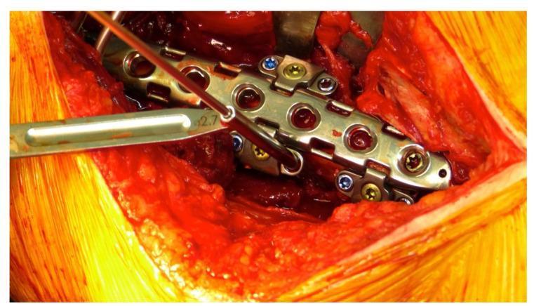
A close-up clinical photograph showing an intraoperative surgical field during orthopedic internal fixation for a periprosthetic fracture. The focal point is a metallic LOQTEQ® Variable Angle (VA) Periprosthetic Plate system secured to a bone. The central locking compression plate (LCP) features multiple circular screw holes. Adherent to the lateral margins of the main plate are specialized attachable hinges designed for variable-angle screw placement. These hinges contain inserted locking screws with color-coded blue and gold heads. A freehand drill guide with a 2.7 mm diameter marking is actively positioned within one of the hinge openings, demonstrating the technique for drilling a pilot hole at a specific angle to bypass existing intramedullary prosthetic hardware. The surgical site displays exposed muscle and soft tissue with moderate hemarthrosis/bleeding typical of open reduction and internal fixation (ORIF) procedures. This image illustrates the application of modular plating systems in complex fracture management where standard monocortical or biaxial screw trajectories are obstructed by an existing implant.
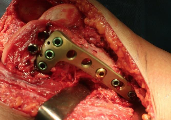
An intraoperative clinical photograph demonstrating an open reduction and internal fixation (ORIF) procedure for a distal femoral fracture. The image shows a locking compression plate (LCP) originally designed for the proximal tibia being utilized in an off-label, inverted orientation to provide anatomical fixation for the medial femoral condyle. The metallic plate is contoured to the bone surface and secured with a combination of cortical and locking screws. Key visible features include the exposed bone and soft tissue of the right knee joint through a medial parapatellar approach, with surgical retractors reflecting the tissue. The educational focus of this image is on unconventional hardware application and surgical salvage techniques for complex intra-articular fractures (AO classification: 33-B2.1). This material is relevant for orthopedic surgery residents and trauma surgeons specializing in lower limb reconstruction.
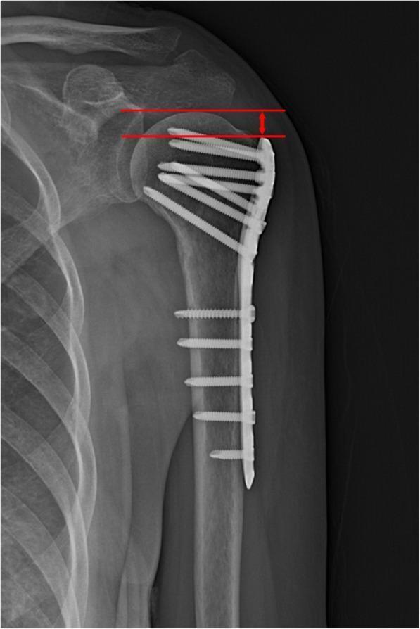
Anteroposterior (AP) x-ray of the shoulder demonstrating a proximal humerus fracture treated with internal fixation. A metallic locking compression plate (LCP) is positioned on the lateral aspect of the humeral shaft, extending superiorly to the greater tuberosity. The construct features multiple locking screws: proximal screws are oriented at varying angles to support the humeral head subchondral bone, while distal screws are inserted perpendicularly into the humeral diaphysis. Educational annotations in red illustrate the methodology for measuring Humeral Head Height (HHH). Two parallel horizontal lines are drawn: the superior line identifies the highest point of the humeral head articular surface, and the inferior line aligns with the top edge of the orthopedic plate. A double-headed vertical arrow indicates the distance between these lines, used clinically to monitor for postoperative loss of fixation or subsidence of the humeral head. The image provides a clear demonstration of orthopedic implant positioning and radiographic assessment parameters for proximal humeral fractures.
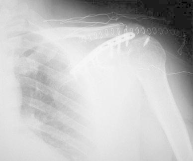
This diagnostic image is an early postoperative anteroposterior (AP) X-ray of the left shoulder. It demonstrates surgical fixation of a scapular spine fracture or pseudoarthrosis. A radiopaque metallic Locking Compression Plate (LCP) is visible, anatomically contoured and positioned along the spine of the scapula. The plate is secured with multiple cortical screws providing internal fixation and compression across the bony disruption. Key anatomical structures visible include the scapula (acromion and spine), the proximal humerus, the clavicle, and the upper rib cage. Radio-dense surgical staples or sutures are also visible in the overlying soft tissue, indicating recent wound closure. The image illustrates orthopedic management for complex scapular injuries and the use of internal fixation to promote bony union in cases of non-union or pseudoarthrosis. The humeral head is noted in the glenohumeral joint, and the hardware appears stable in this early follow-up phase.
LCP locking compression plate mechanism combi hole indications vs DCP
Locking Compression Plate (LCP)
What Is It?
The Locking Head Screw - Core of the LCP
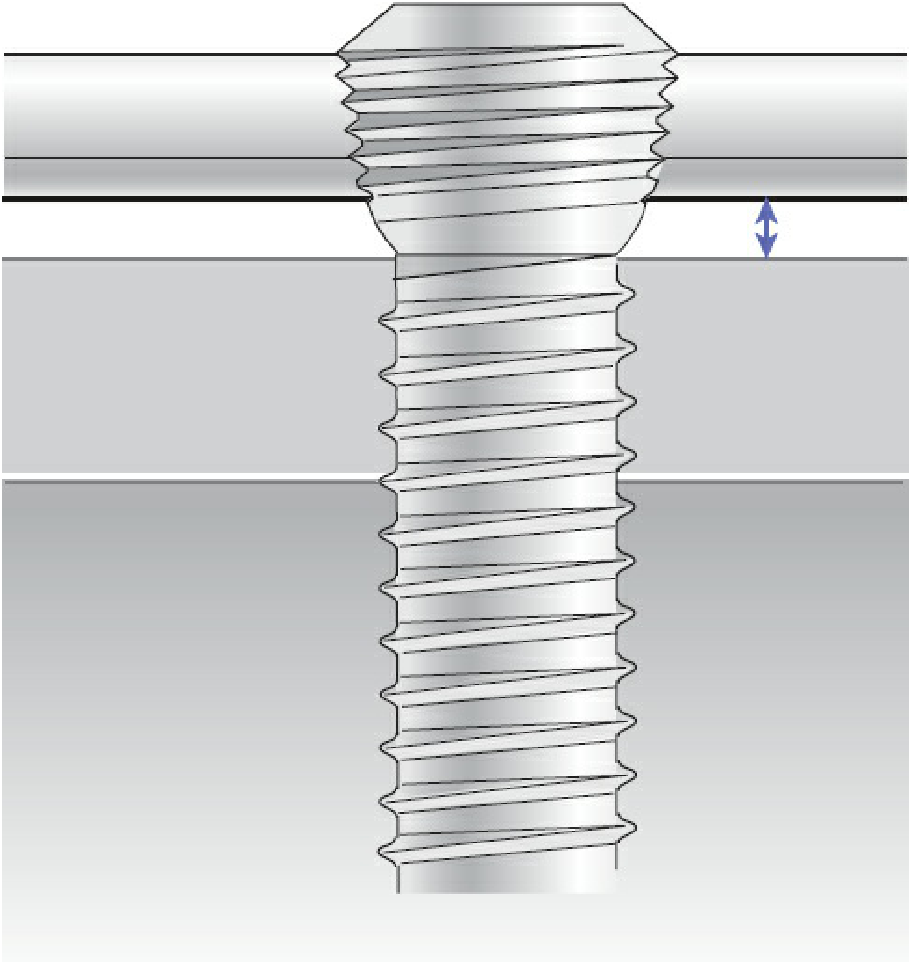
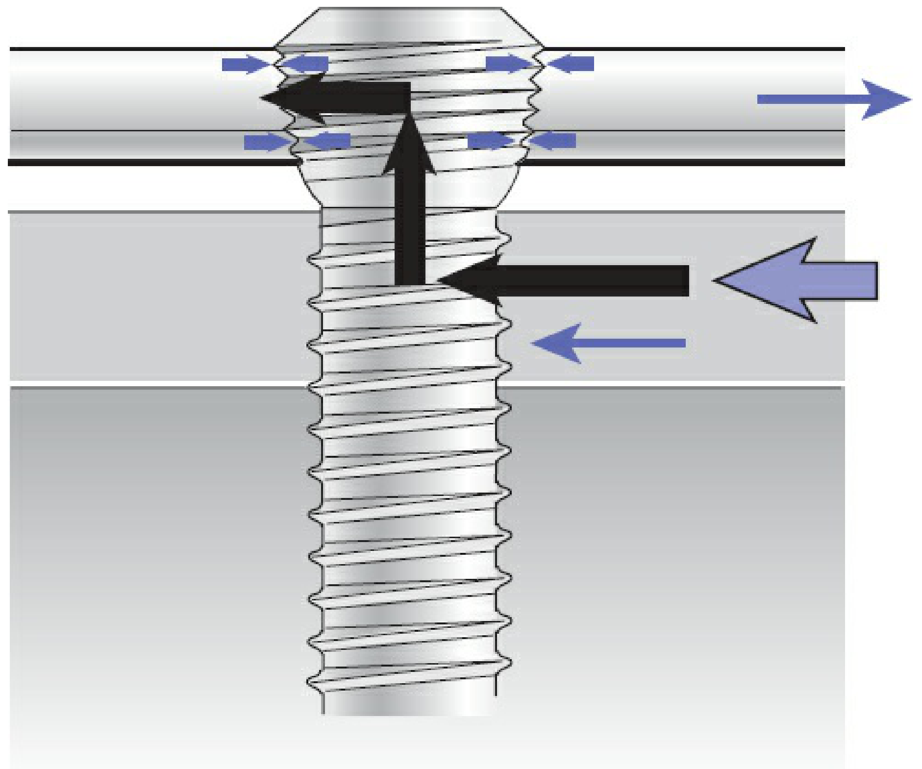
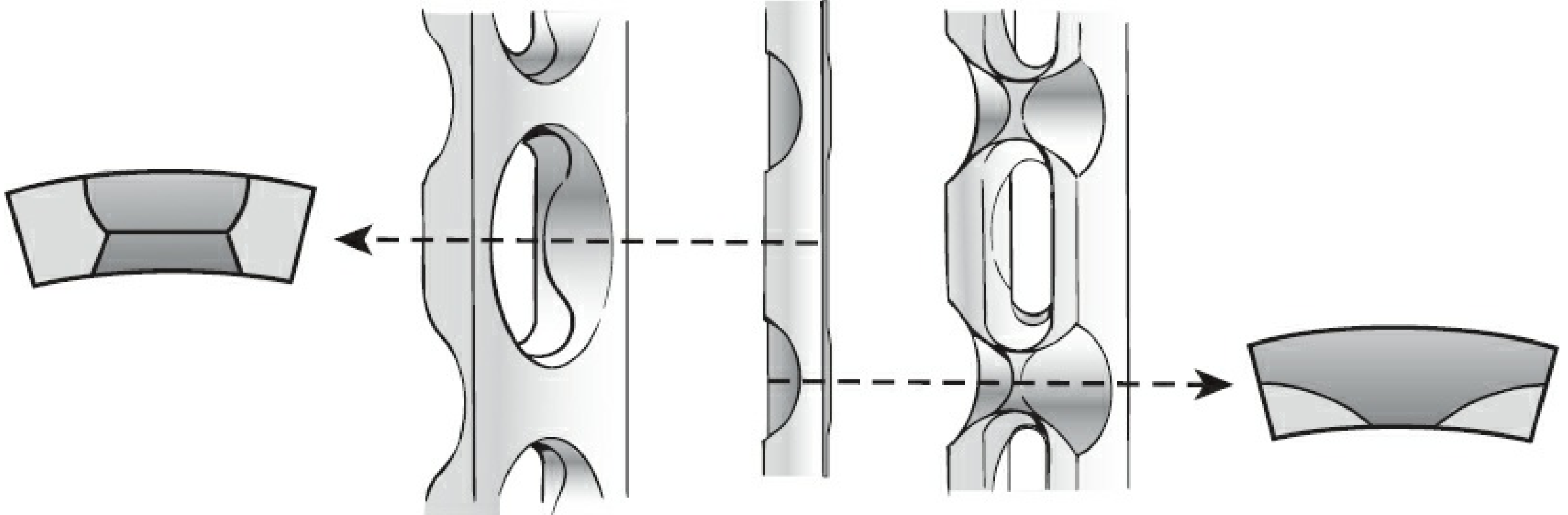
The Combi-Hole - What Makes LCP Unique
| Half | Type | What Goes In | Function |
|---|---|---|---|
| Threaded half | Round with internal threads | Locking screw (threaded head) | Fixed-angle angular stability |
| DCU half | Oval/sloped ramp (DCP-style) | Conventional cortical screw (eccentric) | Axial compression, same as DCP |
- Locking screw only - pure fixed-angle internal fixator
- Conventional screw only - generates compression (DCP mode)
- Conventional screw first for compression, then locking screw - hybrid mode (most common in practice)
Important rule: If a locking screw is placed first, do NOT subsequently insert a conventional screw in the same fragment without loosening and re-tightening the locking screw - this risks spinning the plate on the bone.
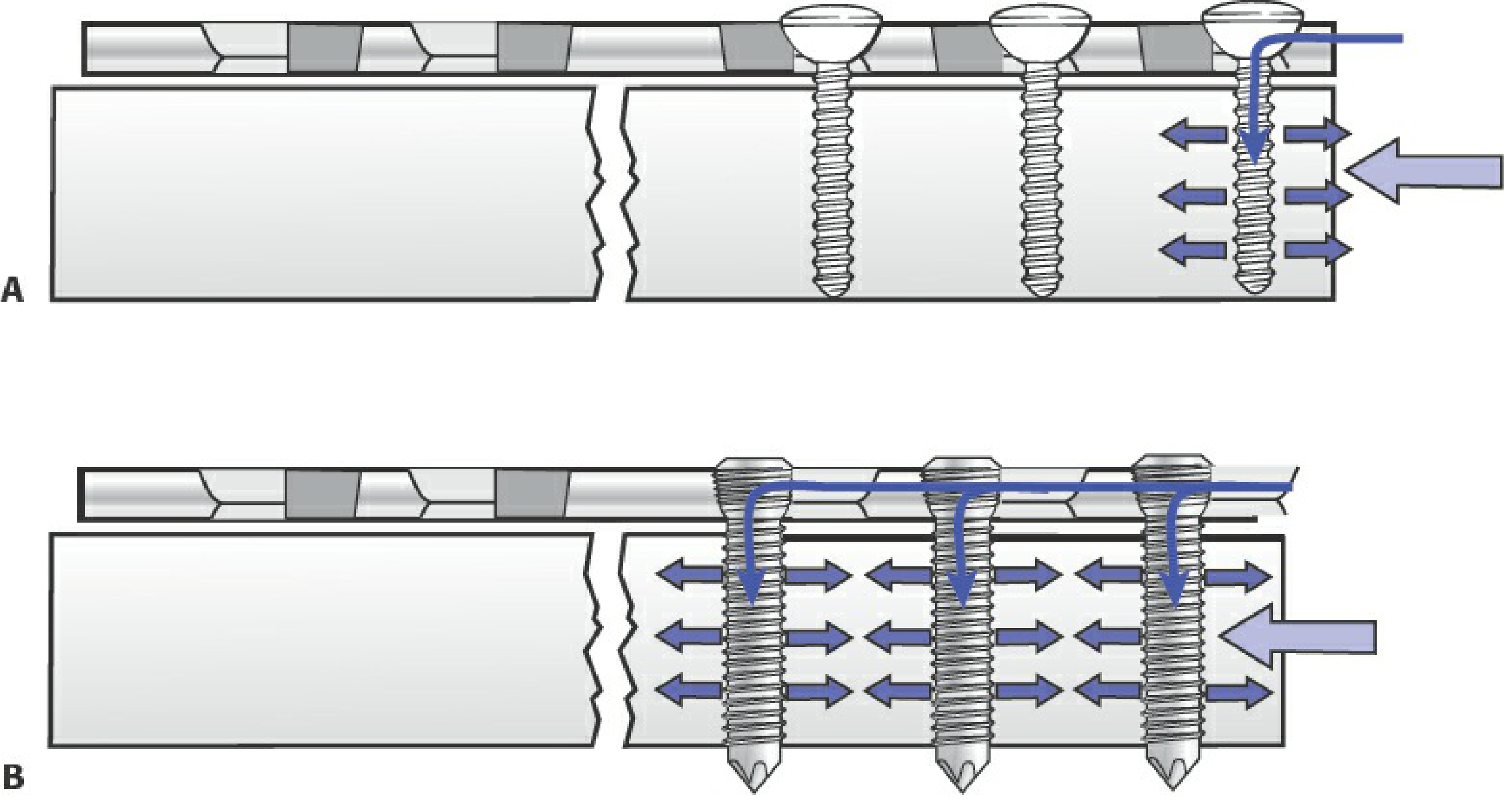
Locked vs Non-Locked Construct Mechanics
| Feature | Conventional (DCP) | Locked (LCP) |
|---|---|---|
| Stability source | Plate-bone friction | Fixed-angle screw-plate thread interface |
| Plate must contact bone? | Yes (friction essential) | No (can be off-bone) |
| Load transfer | Screw toggling, sequential failure | All screws fail simultaneously (parallel) |
| Bone quality required | Good cortical bone | Works in osteoporotic / poor bone |
| Periosteal blood supply | Compromised by plate pressure | Preserved - less biology disruption |
| Screw failure mode | One screw at a time | All screws must fail at once - much stronger pullout |
Variable Angle Locking
- Trade-off: VA locking is not as strong in bending as fixed-angle - construct stability decreases as screw inclination increases.
Modes of Use
| Mode | Technique | When to Use |
|---|---|---|
| Compression | Eccentric conventional screw in DCU half | Simple transverse/short oblique fractures with good bone |
| Neutralization | After lag screw fixation, plate neutralizes forces | Spiral/oblique fractures |
| Bridging | Pure locking screws, spanning comminuted zone | Comminuted, multifragmentary fractures |
| Buttress | Prevents shear/telescoping | Periarticular fractures |
| Tension band | Applied to tension side | Specific bony prominences |
| Hybrid | Mix of locking + conventional screws | Most common - combines compression + angular stability |
Indications (Where LCP Excels Over DCP)
- Osteoporotic bone - locking screws resist pullout far better than conventional screws
- Periarticular / juxta-articular fractures - short metaphyseal segments with little bone for purchase
- Comminuted / multifragmentary fractures - bridge plating without disturbing fracture biology
- Periprosthetic fractures - can combine with cerclage cables
- Percutaneous / MIPO techniques - plate can be slid submuscularly without periosteal stripping
- Non-unions in challenging bone
- Anatomic precontoured plates for: distal femur, proximal tibia, proximal humerus, distal radius, clavicle, calcaneus, etc.
Screw Selection: Bicortical vs Unicortical
| Unicortical Locking | Bicortical Locking | |
|---|---|---|
| Torsional resistance | Less | Significantly better |
| Preferred for | Short periarticular segments, MIPO | Diaphysis, osteoporotic bone |
| Effect on adjacent screws | Less protection | Better protection to adjacent cortical screws |
Clinical Images
Evolution / Generations
| Generation | System | Key Feature |
|---|---|---|
| 1st | LISS (Less Invasive Stabilization System) | Fixed-angle, unicortical self-drilling, percutaneous jig |
| 2nd | LCP | Combi-hole: combines LISS locking + DCP compression |
| Current | Anatomic precontoured LCPs + VA-LCP | Site-specific geometry, variable-angle up to ±15° |
Pitfalls / Complications to Know
- Stress shielding - overly stiff locked constructs in diaphysis may impair callus formation -> consider hybrid mode or far cortical locking (FCL)
- Cross-threading - locking screw must be inserted perpendicular to the fixed-angle hole; any angulation causes incomplete thread engagement and loss of bending stability
- Plate proud / poor contouring - unlike DCP, an LCP does NOT need to touch bone, but poor contouring can prevent reduction
- Conventional screw after locking screw (same fragment) - can rotate the plate; must loosen locking screw first
- Unicortical screws only - significantly lower torsional resistance vs bicortical; do not use alone in diaphyseal fixation
Summary Comparison: DCP vs LC-DCP vs LCP
| DCP | LC-DCP | LCP | |
|---|---|---|---|
| Stability mechanism | Plate-bone friction | Plate-bone friction | Fixed-angle screw-plate lock |
| Plate-bone contact | Broad | Limited/scalloped | None required |
| Compression possible? | Yes (eccentric screw) | Yes (eccentric screw) | Yes (DCU half of combi-hole) |
| Periosteal biology | Compromised | Better | Best preserved |
| Osteoporotic bone | Poor | Poor | Excellent |
| Hole design | Oval/DCU | Oval/DCU | Combi-hole (threaded + DCU) |
| Bone healing type | Primary | Primary | Primary or secondary (bridge) |