
Anesthesia workstation where can i prepare for my residency exams
Reading File
The anesthesia workstation is a key exam topic covering machine components, gas delivery, safety features, and checks. Let me search the library for comprehensive content.
Searching sources...
Finding Sources
Finding Sources
Excellent - I have Miller's (10e), Morgan & Mikhail (7e), and Barash (9e). Let me pull the key content from all three simultaneously.
Reading File
Reading File
Reading File
Good start. Now let me get the detailed content from Morgan & Mikhail on the machine components and safety features, plus the Barash anatomy section and Miller's functional anatomy.
Reading File
Reading File
Reading File
Excellent content. Let me now get the key images and the checkout/safety sections plus vaporizer content from Morgan & Mikhail.
Reading File
Reading File
Reading File
I now have rich, comprehensive content from all three major anesthesia textbooks. Let me also fetch some of the key diagrams to include visually.
Loading Image
Loading Image
Reading File
I now have everything I need for a comprehensive, well-organized residency exam review on the anesthesia workstation. Let me compile the answer.
The Anesthesia Workstation - Residency Exam Review
Sources: Miller's Anesthesia 10e, Morgan & Mikhail's Clinical Anesthesiology 7e, Barash Clinical Anesthesia 9e
Overview
The anesthesia workstation receives medical gases from a supply, controls and reduces their pressure to safe levels, vaporizes volatile anesthetics into the final gas mixture, and delivers the result to a breathing circuit connected to the patient's airway. Equipment-related adverse outcomes are rarely due to device malfunction - misuse and failure to verify machine function before use account for most incidents, about 3x more prevalent than device failure in ASA Closed Claims data.
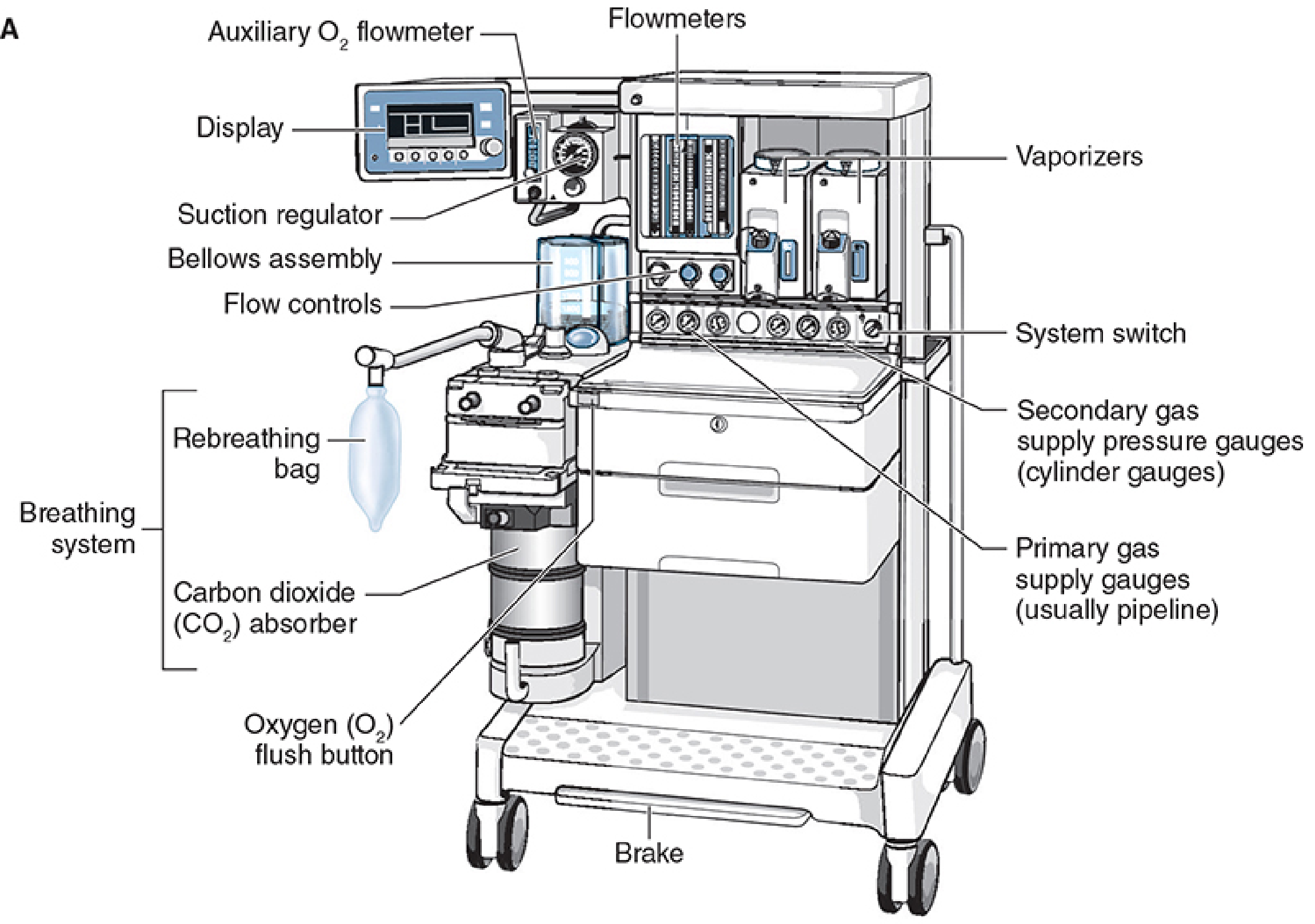
Here is a labeled diagram of a modern anesthesia machine (Datex-Ohmeda Aestiva):
And the full internal gas circuit schematic:
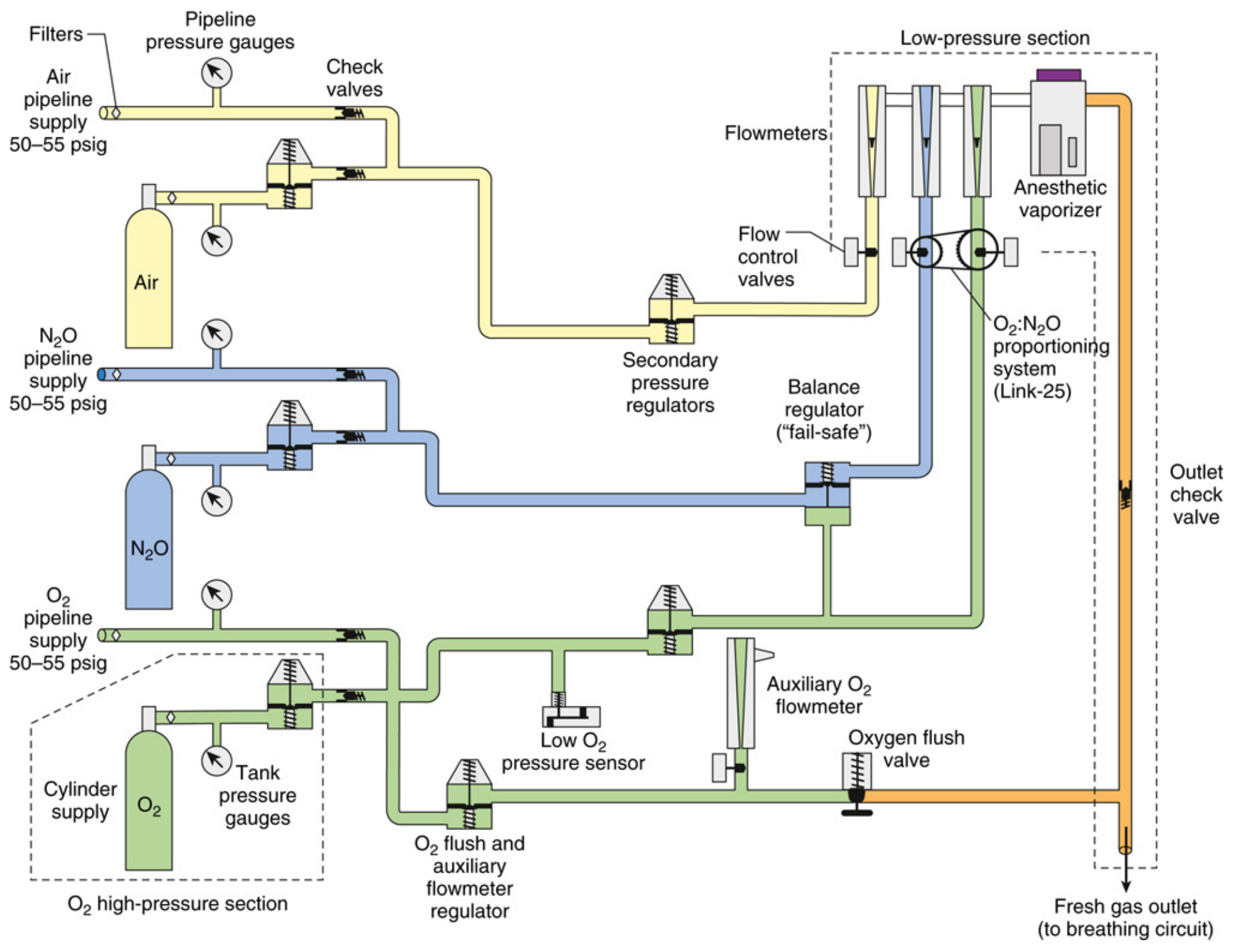
1. Three Pressure Sections (HIGH YIELD)
| Section | Pressure Range | Contents |
|---|---|---|
| High-pressure | O2: up to 2,200 psig; N2O: up to 750 psig | E-cylinders and primary pressure regulators only |
| Intermediate-pressure | 45-55 psig (pipeline: 50-55 psig; cylinder post-regulator: 45 psig) | Pipeline inlets, secondary regulators, fail-safe valve, flow control valves |
| Low-pressure | Below flow control valves | Flowmeters (rotameters), vaporizer manifold, vaporizers, fresh gas outlet |
The flow control valves are the anatomic landmark separating the intermediate and low-pressure sections.
- Miller's Anesthesia 10e, p. 2228-2229; Barash Clinical Anesthesia 9e, p. 1931
2. Gas Supply Sources
Pipeline (primary): Hospital pipeline supplies O2, N2O, and air at ~50-55 psig via Diameter Index Safety System (DISS) connectors (non-interchangeable, keyed by diameter).
E-Cylinders (backup):
- O2: 2,200 psig when full; regulated down to ~45 psig
- N2O: 745 psig when full; regulated down to ~45 psig
- Mounted via the hanger yoke assembly, which includes the Pin Index Safety System (PISS) - unique pin arrangements per gas to prevent wrong-gas connection errors
3. Safety Systems (HIGH YIELD)
A. Fail-Safe Valve (Oxygen Failure Cutoff Valve)
Located downstream of the N2O supply in the intermediate-pressure circuit. It shuts off or proportionally decreases N2O flow if oxygen supply pressure drops. This prevents hypoxia from an N2O-dominant mixture but does NOT guarantee a non-hypoxic mixture on its own.
- Alarm triggers when O2 supply pressure falls below ~30 psig (high-priority alarm)
B. O2/N2O Proportioning System (Link-25 / ORMC)
- Links N2O flow to O2 flow mechanically or electronically
- Ensures a minimum FiO2 of 25% is maintained at the common gas outlet
- Drager uses the "Oxygen Ratio Monitor Controller" (ORMC); Datex-Ohmeda uses "Link-25"
C. Flowmeter Sequence
- O2 flowmeter must be placed downstream (nearest) to the vaporizer in all machines
- If a leak develops upstream, any hypoxic gas is diluted by O2 from the downstream O2 flowmeter
- This is the most important safety arrangement in the rotameter bank
D. Minimum O2 Flow
- A minimum flow resistor ensures some O2 enters the circuit even if the operator forgets to turn on O2 flow
4. Flowmeters (Thorpe Tubes / Rotameters)
- Constant-pressure, variable-orifice design
- Float rises until the pressure drop across it equals the float's weight
- Calibrated per gas: flow depends on viscosity at low (laminar) flows (Poiseuille's law) and density at high (turbulent) flows
- Floats rotate constantly to stay centered and reduce wall friction effects
- Modern electronic machines use flow restrictors and pressure-drop sensors; a backup mechanical Thorpe tube for O2 is always provided
- Causes of malfunction: debris in the tube, tube not vertical, float stuck at top
5. Vaporizers (HIGH YIELD)
All modern vaporizers are:
- Agent-specific (keyed filling ports prevent wrong-agent loading)
- Temperature-compensated - deliver constant agent concentration regardless of temperature changes or flow rate through the vaporizer
- Variable bypass type for most agents (halothane, isoflurane, sevoflurane, enflurane): a proportion of fresh gas bypasses the vaporizing chamber; the ratio adjusts with temperature
Desflurane exception: Desflurane has a boiling point near room temperature (22.8°C) and high vapor pressure, so it uses a heated pressurized vaporizer (Tec 6) - not a variable bypass type. The reservoir is electrically heated to 39°C, producing a vapor pressure of 1,550 mmHg, which is then injected into the fresh gas stream.
GE Aladin Cassette / Electronic Injector Vaporizers: Use electronic injection of agent vapor directly into the gas stream - no separate vaporizer manifold needed.
6. Breathing Circuit - Circle System
The circle system is the standard rebreathing circuit used with anesthesia machines. Key components:
- Fresh gas inlet
- Inspiratory and expiratory unidirectional valves
- Y-piece to patient
- Reservoir (rebreathing) bag
- CO2 absorber canister (soda lime or barium hydroxide lime)
- APL (Adjustable Pressure-Limiting) valve - spill valve for manual/spontaneous ventilation
- Ventilator bellows assembly
CO2 absorbents: Soda lime contains NaOH + Ca(OH)2 with a color indicator. Exhausted granules change color. Compound A is formed with sevoflurane + soda lime at low flows - clinically relevant at <1 L/min fresh gas flow.
7. Ventilators
Traditional design: Pneumatically driven bellows, electronically controlled (double-circuit system)
- Ascending bellows (upward fill during expiration) are safer - disconnection is visible as the bellows fail to fill
- Descending bellows continue to move even with a circuit disconnection (weighted), masking disconnect
Piston ventilators: Single-circuit, electrically driven; better accuracy for:
- Very poor lung compliance
- Small pediatric patients
- Precise tidal volumes regardless of circuit compliance
Electric turbine ventilators: Used in some newer workstations.
Key exam points:
- During ventilator inspiration, the spill valve (APL) is bypassed and the ventilator's pop-off valve closes - fresh gas flow from the common outlet adds to the delivered tidal volume (fresh gas coupling)
- Never use the O2 flush valve during the inspiratory cycle - the surge (600-1,200 mL/s at 35-55 psig) goes directly to the patient's lungs
- Three mandatory disconnect alarms: low peak inspiratory pressure, low exhaled tidal volume, low exhaled CO2
8. Oxygen Flush Valve
- Delivers O2 at 35-75 psig directly to the common gas outlet, bypassing the flowmeters and vaporizer
- Flow rate: 35-75 L/min (some sources 600-1,200 mL/s)
- Bypasses the vaporizer - useful to rapidly purge the circuit but dilutes anesthetic and can cause awareness
- Dangerous during mechanical ventilation (see above)
9. Waste Gas Scavenging System
- Collects waste gas from the APL valve (manual/spontaneous) and ventilator spill valve (mechanical)
- Passive (relies on hospital vacuum) or active (powered) systems
- Operating room waste gas pollution can be a chronic health hazard to surgical personnel
- Open interface reservoir bags buffer flow peaks; closed interface systems use negative/positive pressure relief valves
10. Oxygen Analyzers
Three types (exam favorite):
| Type | Mechanism | Notes |
|---|---|---|
| Paramagnetic | O2 is paramagnetic; deflects in a magnetic field | Self-calibrating, no consumable parts, fast response - can differentiate inspired vs. expired O2 |
| Polarographic (Clark electrode) | Electrochemical; current proportional to O2 partial pressure | External power required |
| Galvanic (fuel cell) | Same principle as Clark but self-powered by its own chemistry | Consumable cell |
- Sensor placed in the inspiratory or expiratory limb (not the fresh gas line)
- Low-level O2 alarm must be automatically activated when the machine is turned on
11. Pre-Anesthesia Checkout (ASA 2008 Recommendations) - HIGH YIELD
7 Basic Safety Requirements for Anesthesia Delivery:
- Reliable delivery of O2 at any concentration up to 100%
- Reliable means of positive-pressure ventilation
- Backup ventilation equipment available and functioning
- Controlled release of positive pressure from the breathing circuit (APL valve)
- Anesthetic vapor delivery (if planned)
- Adequate suction
- Means for patient monitoring per standards
Checkout Frequency:
- Daily: Full checkout (15 items total) before first case
- Before each subsequent case: Abbreviated 8 items (e.g., verify O2 supply, check calibration, circuit integrity, ventilator function, monitors)
Key fact: Anesthesia providers frequently skip complete checkouts, and even automated self-tests on modern workstations do NOT assure all basic safety requirements are met. Machine diversity has made generic checklists less applicable - institution-specific protocols are now standard.
- Miller's Anesthesia 10e, p. 2402-2403; Morgan & Mikhail 7e, p. 104-105
12. Monitoring From the Workstation
Parameters recorded from the anesthesia workstation include:
- FiO2, inspired/expired O2, N2O, volatile agent concentrations
- Fresh gas flows
- Minute volume, tidal volume, respiratory rate
- Peak inspiratory pressure (PIP), PEEP
- Ventilator mode
- EtCO2
Quick Exam Recap
| Topic | Key Fact |
|---|---|
| Fail-safe valve | Cuts N2O if O2 pressure drops - does NOT guarantee non-hypoxic mix |
| O2/N2O proportioning | Minimum FiO2 25% guaranteed at common gas outlet |
| O2 flowmeter position | Always nearest (downstream) to vaporizer |
| Desflurane vaporizer | Heated, pressurized - NOT variable bypass |
| Ascending vs. descending bellows | Ascending = safer (disconnect visible) |
| O2 flush during inspiration | Dangerous - barotrauma risk |
| Disconnect alarms (3) | Low PIP, low exhaled TV, low EtCO2 |
| PISS | Pin Index Safety System - cylinder gas ID |
| DISS | Diameter Index Safety System - pipeline connection ID |
| Pre-op checkout | Daily full (15 items); before each case abbreviated (8 items) |
| Tidal volume discrepancy causes | Circuit compliance, gas compression, FGF coupling, airway leaks, set pressure limit |
References: Morgan & Mikhail's Clinical Anesthesiology 7e, Ch. 4 (pp. 104-130); Miller's Anesthesia 10e, Ch. 20 (pp. 2228-2403); Barash Clinical Anesthesia 9e, Ch. 25 (pp. 1924-1940)
This is a shared conversation. Sign in to Orris to start your own chat.