
Bearing surfaces thr lubrication part only modes of lubrication
Modes of Lubrication - Bearing Surfaces in THR
Overview
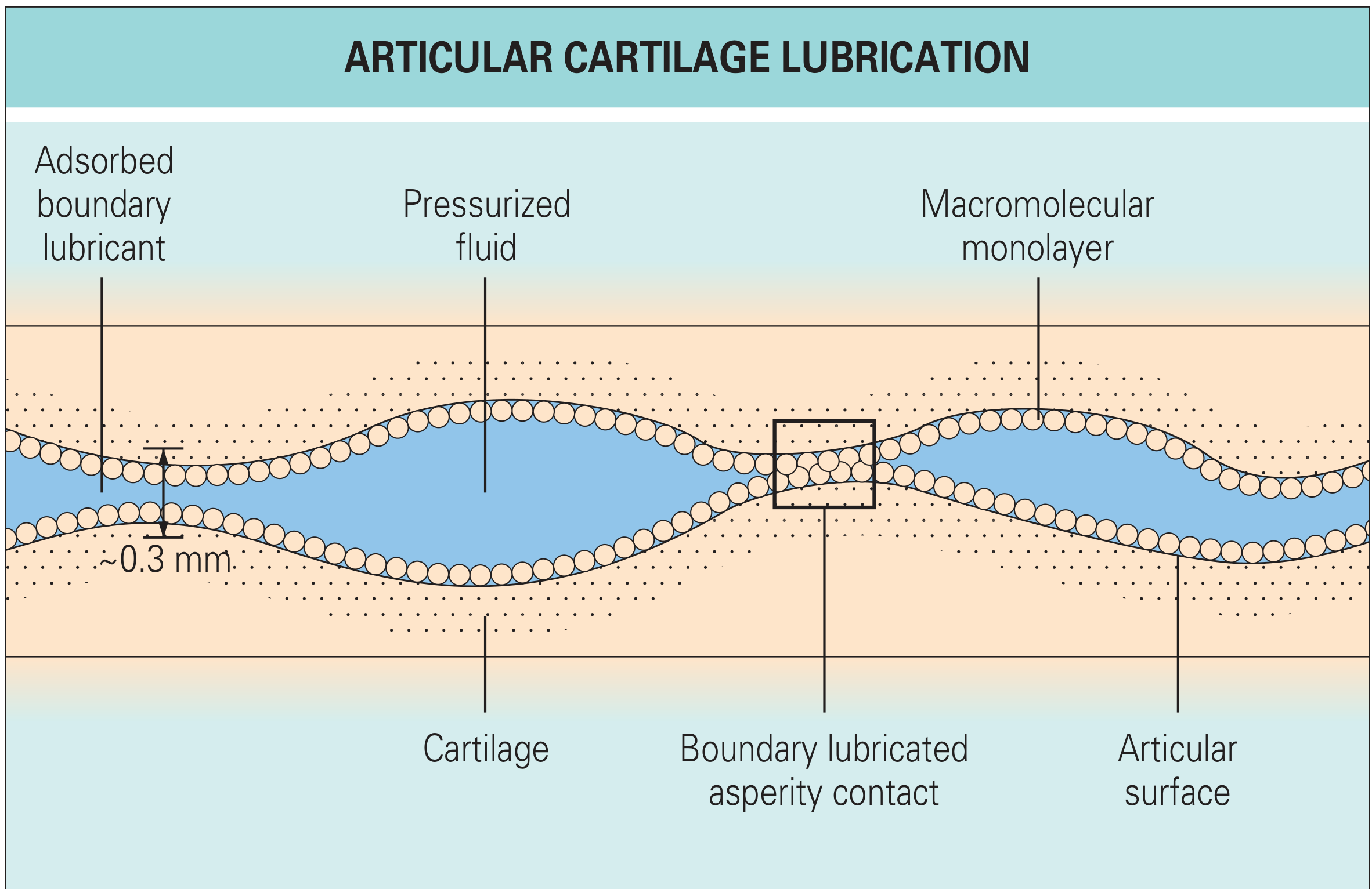
- Boundary Lubrication
- Fluid Film Lubrication (with sub-types: Hydrodynamic, Elastohydrodynamic, Squeeze Film)
1. Boundary Lubrication
- A single monolayer of lubricant molecules is adsorbed onto each bearing surface
- The lubricant molecules physically attach to the surface and carry the load directly
- In natural joints, this is achieved by a macromolecular monolayer (lubricin / surface-active phospholipids) attached to the articular surface
- These layers directly contact each other, carrying loads and reducing friction
- Film thickness ~equals the roughness of the bearing surface (~0.3 mm)
- Operates predominantly at low velocities and high loads (when fluid film cannot be maintained)
Key feature: surfaces are essentially in contact; the lubricant prevents direct metal-on-metal or cartilage-on-cartilage adhesion.
2. Fluid Film Lubrication
- Viscosity of the lubricant
- Shape of the gap between the two bearing surfaces
- Relative velocity of the surfaces
Sub-types of Fluid Film Lubrication
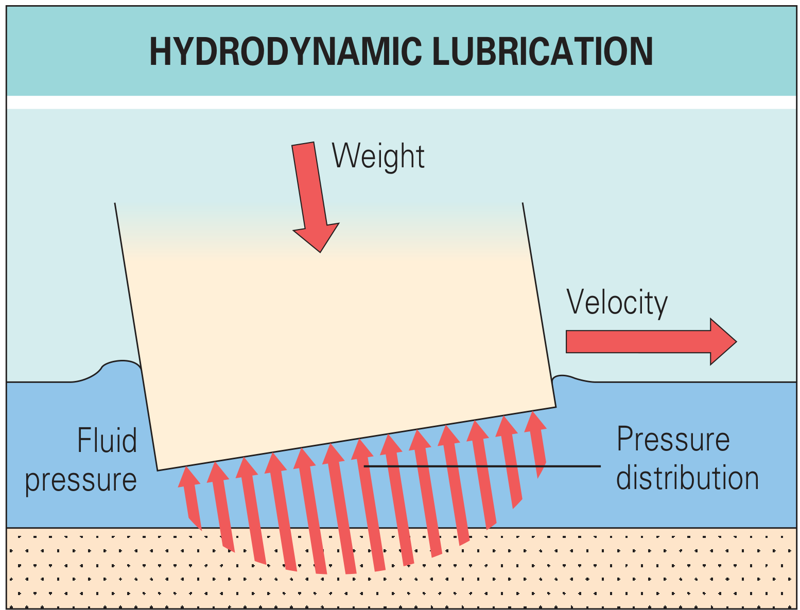
a) Hydrodynamic Lubrication
- Motion at sufficiently high velocity tilts the bearing and forms a wedge shape of entrained lubricant
- Viscous properties of the fluid create pressure within the film to support the load
- Surfaces are fully separated - no solid-solid contact
- Works well in rigid bearing surfaces (e.g., metal-on-metal at high speeds)
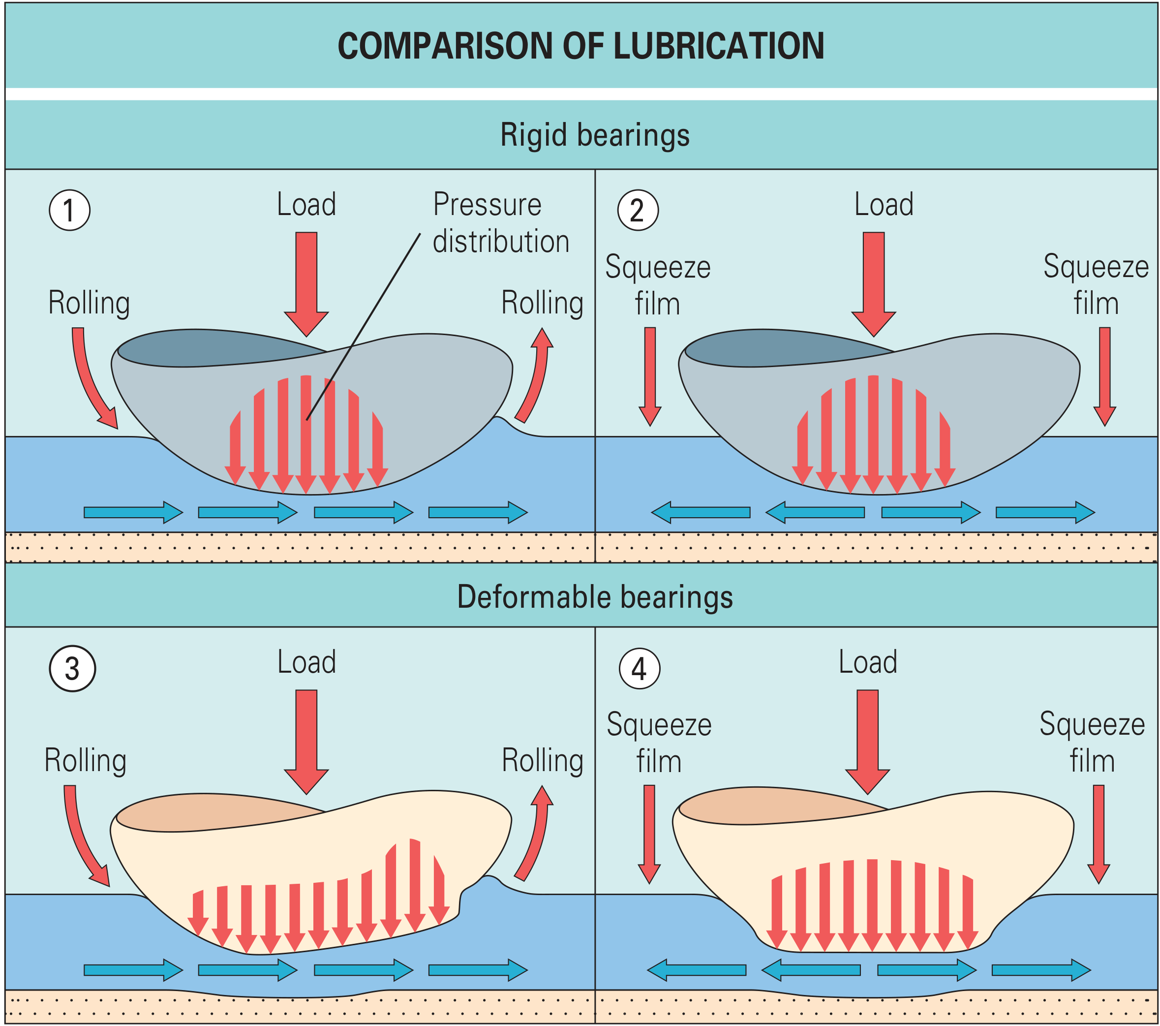
b) Elastohydrodynamic (EHD) Lubrication
- The primary lubrication mechanism for articular cartilage during dynamic function
- Occurs when bearing materials are not rigid and stiff (as with cartilage)
- As surfaces move and entrain synovial fluid, the fluid pressure causes surface deformation (AC flattening)
- This deformation:
- Increases the contact area
- Increases load-carrying capacity
- Reduces escape of lubricant from between surfaces
- Generates a longer-lasting film
- Produces lower stress concentration within joint surfaces
- Both hydrodynamic (sliding) and squeeze film (impact) actions can drive EHD lubrication
c) Squeeze Film Lubrication
- Occurs when two surfaces approach each other rapidly (e.g., at heel strike)
- Fluid is squeezed out from between the surfaces but the viscous resistance of the fluid generates a transient pressure that carries the load
- Very important at the start of motion and during high-impact loading before hydrodynamic film is established
- In deformable (EHD) bearings, surface deformation spreads the load over a larger area, prolonging the squeeze film effect
3. Mixed Mode Lubrication
- Fluid film pressure supports loads in areas of non-contact (troughs between surface asperities)
- Boundary lubrication operates in areas of contact (at surface asperities)
Comparison: Hydrodynamic vs. Squeeze Film (Rigid vs. Deformable)
Hydrodynamic Lubrication - Principle
Coefficient of Friction - Comparative Data
| Surface | Coefficient of Friction |
|---|---|
| Human joint (natural) | 0.002 - 0.04 |
| Metal-on-UHMWPE (THR) | 0.05 - 0.15 |
Role of Synovial Fluid
- Synovial fluid is thixotropic: becomes fluid when agitated, settles when at rest
- This property allows it to serve boundary lubrication needs at low velocities and fluid film needs at high velocities
- Joint effusion disrupts this velocity-dependent property, reducing lubrication quality and increasing surface damage
- Key molecular lubricants: hyaluronan, lubricin, and phospholipids - each plays a different role at different stages of motion, and none alone can explain the extremely low friction of natural joints
Summary Table
| Mode | Mechanism | Dominant Condition | Surface Contact? |
|---|---|---|---|
| Boundary | Monolayer adsorbed to surface | High load, low velocity, start of motion | Yes (indirect) |
| Hydrodynamic | Wedge-shaped fluid film entrained by motion | High velocity, sustained motion | No |
| Squeeze film | Transient pressure from converging surfaces | Impact loading, heel strike | Transitional |
| Elastohydrodynamic | Fluid film + surface deformation | Dynamic function of cartilage/soft bearings | No (surfaces deform) |
| Mixed | Combination of boundary + fluid film | Most real joint conditions | Partial |
4 bearing couples with wear rates pseudotumor ALTR in MOM, DUAL MOBILITY BOUSQUET CONCEPT trillion corrosion clinical applications of tribology 6 marks structured answer
Bearing Surfaces in THR - Structured Answer (6 Marks)
A. THE FOUR BEARING COUPLES - Wear Rates
1. Metal-on-Polyethylene (MoP) - Conventional UHMWPE
| Parameter | Value |
|---|---|
| Introduced by | Sir John Charnley, 1960s |
| Linear wear rate | 0.1-0.2 mm/year (conventional UHMWPE) |
| Volumetric wear | High (billions of submicron particles/year) |
| Osteolysis threshold | >0.1 mm/year linear wear |
| Dominant wear mechanism | Adhesive wear (most important for osteolysis) + abrasive wear |
- Backside wear - additional PE debris from PE insert micromotion against metal shell
- PE particles (submicron size) stimulate osteolysis when count exceeds 10 billion particles per gram of tissue
- Osteolytic lesions typically appear after 10 years with conventional PE
2. Metal/Ceramic-on-Highly Cross-Linked Polyethylene (HCLPE) - Most Popular Today
| Parameter | Value |
|---|---|
| Radiation dose for cross-linking | 5-15 Mrad |
| Linear wear rate | 0.01-0.05 mm/year (10x reduction) |
| Status | Most popular bearing option in North America |
- Rates of osteolysis have fallen dramatically with widespread HCLPE adoption
- HCLPE allows larger-diameter femoral heads without excessive linear wear
- Wear rate largely independent of head diameter
- Disadvantage: Reduction in mechanical properties (fracture toughness, tensile strength) - catastrophic failure is extremely rare
- Free radical problem: Residual free radicals after irradiation cause oxidative degradation; addressed by:
- Remelting (>135°C) - eliminates free radicals but reduces crystallinity
- Annealing (below melting point) - preserves crystallinity but less effective
- Vitamin E doping - scavenges free radicals without remelting stage
- Currently Ceramic-on-HCLPE is favored over Metal-on-HCLPE due to trunnion corrosion concerns
3. Metal-on-Metal (MoM)
| Parameter | Value |
|---|---|
| Particle size | 0.015-0.12 µm (nanometer-sized) |
| Linear wear | Very low |
| Volumetric wear | Very low |
| BUT: absolute particle count | Greater than comparable PE bearing |
- Run-in wear: Higher wear in first 1 million cycles (~1 year of high activity) - polishes out high points, carbide asperities, and areas out-of-round
- After run-in: lower steady-state wear rate
- Now largely abandoned due to ALTR (see Section C)
4. Ceramic-on-Ceramic (CoC)
| Parameter | Value |
|---|---|
| Material | Alumina or alumina matrix composite (AMC) |
| Wear rate | Lowest of all bearing couples |
| Coefficient of friction | Very low |
| Unique complication | Squeaking (up to 23% with large-diameter delta ceramic) |
- 1st generation alumina - head fracture rate up to 13.4% (due to neck impingement, adverse head-neck ratio, poor manufacturing)
- Modern AMC (delta ceramic): fracture rate ~1 in 100,000 (0.001%)
- Compare to pure alumina: 1 in 5000 (0.02%)
- Ceramic head change: Any new ceramic head placed on a used femoral neck must use an internal titanium adapter sleeve - high points on roughened neck cause burst fracture
- Stripe wear - area of roughness from repetitive subclinical subluxation (head rotates on cup edge)
- After ceramic fracture: microscopic shards remain, severely abrasive - must replace with another CoC (use HCLPE if unavailable)
B. PSEUDOTUMOR AND ALTR in Metal-on-Metal (MoM)
Definition
- Metal-on-metal articulating bearing surfaces
- Modular neck femoral components
- Stems with modular femoral heads (trunnion/taper corrosion)
Pathogenesis
- Nanometer-sized MoM particles dissolve to generate cobalt (Co²⁺) and chromium (Cr³⁺) ions
- Normal wear: serum Co and Cr levels mildly elevated (1-3 µg/L)
- ALVAL (Aseptic Lymphocyte-Dominated Vasculitis-Associated Lesion): Delayed hypersensitivity reaction to metal ions; CD4+ T-lymphocyte mediated
- Local tissue necrosis + cystic masses = pseudotumor
- More common in women (smaller head diameter, higher inclination, higher wear)
Metal Ion Levels and ALTR Risk (Campbell's Table 4.10)
| Component Type | Cobalt (µg/L) | Chromium (µg/L) | Co/Cr Ratio |
|---|---|---|---|
| Metal-on-polyethylene taper | >1 (95/94% sens/spec) | - | >2 |
| Metal-on-metal bearing | >3-7 | Variable | >1 suggests MoM failure |
Diagnosis
- Serum Co and Cr levels - first-line screening
- ESR, CRP - may be elevated in ALTR alone (mimics infection)
- Ultrasound or MARS MRI (Metal Artifact Reduction Sequence) - imaging gold standard for pseudotumor characterization
Contraindications to MoM
- Women of childbearing age (metal ions cross placenta)
- Renal failure (metal ions no longer eliminated)
- Metal hypersensitivity
Outcomes
- Results of ALTR surgery are generally poor - high rates of infection, instability, reoperation
- Refer to centers with required implant availability and surgical expertise
C. DUAL MOBILITY - THE BOUSQUET CONCEPT
Historical Origin
- Designed by Prof. Gilles Bousquet in France in 1974 (first implanted 1976)
- Concept: use two articulating interfaces to increase effective head-to-neck ratio and range of motion without increasing head size proportionally
Design Principle (The "Double Mobility" Concept)
Small metal head (22-28 mm)
↕ Inner articulation (small head in large PE ball)
Large PE outer ball ("mobile bearing" or "retentive cup")
↕ Outer articulation (large PE ball in metal shell)
Metal acetabular shell
- A small-diameter femoral head articulates with a large outer polyethylene liner (forming a large-diameter bipolar construct)
- The outer PE ball then articulates with the metal acetabular shell
- Two articulating surfaces = dual mobility
Biomechanical Advantages
| Feature | Effect |
|---|---|
| Large outer diameter | Larger jump distance (force to dislocate) |
| High head-neck ratio | Greater impingement-free ROM |
| Two bearing surfaces | Distributed motion, reduced wear per interface |
| No neck impingement | Eliminates primary dislocation mechanism |
- Provides greater impingement-free range of motion
- Larger head-to-neck ratio reduces dislocation risk dramatically
Clinical Applications
- Primary THA in high-risk dislocation patients: Poor abductors, neuromuscular disease, cognitive impairment
- Revision THA - historically the main indication
- Conversion of failed hemiarthroplasty - convert MoM monoblock to dual mobility on femoral side
- Low dislocation rates reported in both primary and revision settings
Complications
- Intraprosthetic dislocation (IPD): Dislocation of the inner head from the outer PE ball - requires open reduction - unique to dual mobility
- Outer bearing PE wear - long-term concern (outer articulation is metal-on-PE)
- Acetabular component: monoblock (no screws) or modular (ensure metal liner is properly seated)
D. TRUNNION CORROSION ("TRUNNIONOSIS")
Definition
Mechanism
- Fretting = micromotion at taper junction under cyclic loading
- Corrosion = electrochemical degradation of metal at the fretting site
- Combined process releases Co and Cr ions and metallic debris
- Can cause ALTR identical to MoM bearing failure
Contributing Factors (not fully elucidated)
- Large femoral head diameter (greater moment at taper)
- CoCr head on titanium stem (dissimilar metal galvanic corrosion)
- Increased patient activity / body weight
- Longer neck length (increased lever arm)
- Modular femoral neck junctions (additional taper = additional corrosion site)
Clinical Significance
- Concerns about trunnion corrosion have reduced use of CoCr femoral heads in favor of ceramic heads worldwide
- Metal debris from trunnion corrosion may be responsible for osteolysis appearing within first 2-3 years (vs. PE wear osteolysis which appears after 10 years)
- Management: revision to ceramic head with titanium adapter sleeve
E. CLINICAL APPLICATIONS OF TRIBOLOGY IN THR
| Tribological Principle | Clinical Application |
|---|---|
| Lower coefficient of friction | Ceramic heads preferred over CoCr in modern practice |
| Wear rate data | HCLPE chosen to reduce osteolysis; conventional PE avoided in young patients |
| Lubrication regime | Large-diameter MoM heads exploited fluid-film lubrication - theoretical advantage negated by ALTR |
| Run-in wear (MoM) | High initial wear in MoM = initial metal ion peak; clinically important in screening period |
| Particle size & number | MoM nano-particles more immunogenic per particle despite lower volumetric wear |
| Osteolysis threshold | Linear wear >0.1 mm/year triggers revision planning |
| Head-neck ratio | Dual mobility design maximizes ratio, minimizes dislocation |
| Surface roughness (Ra) | Ceramic heads have residual pits causing some roughness; metal smear transfers metal onto ceramic surface and increases Ra, increasing wear |
| Trunnion tribocorrosion | Drives use of ceramic heads and discourages CoCr-on-titanium taper combinations |
| Third-body wear | Avoid cement debris, bone fragments in joint; causes abrasive scratching of PE |
| Stripe wear | Indicator of subclinical subluxation; causes localized roughness and increased wear |
Recent advances in evaluation and management of rotator cuff tears, arthroscopic repair, what examiner expects 15 marks structured answer to knruhs 4 paper theory
rotator cuff arthroscopic repair double row suture bridge technique
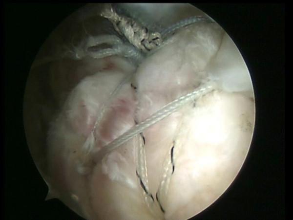
This arthroscopic clinical photograph demonstrates the final intraoperative result of a rotator cuff repair using a double-pulley and suture bridge technique. The field of view shows the rotator cuff tendon secured over the footprint of the humeral head. Key visible elements include multiple high-strength, braided sutures (FiberWire) arranged in a 'suture bridge' configuration. Thicker knotted sutures at the medial aspect indicate the initial medial row fixation point. Thinner, parallel white strands span across the superior surface of the tendon, applying compression to optimize tendon-to-bone contact. The underlying soft tissue appears white and fibrous, characteristic of tendon morphology, with localized areas of mild erythema and vascularization consistent with surgical manipulation. This imaging serves as a pedagogical reference for advanced orthopedic surgical techniques in sports medicine, illustrating the successful compression and stabilization of a tendon graft via knotless and knotted anchor systems.
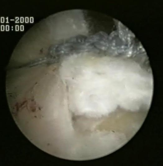
Arthroscopic clinical photograph showing a surgical repair of the rotator cuff using the double-pulley technique. The image captures a white, fibrous tendon bridge being reinforced with high-strength non-absorbable sutures (likely #2 FiberWire). A pre-tied six-throw surgeon's knot is visible, appearing as a dark, textured mass positioned over the superior aspect of the tendon bridge. Two free suture limbs extend from the knot, which are being tensioned to transport the knot into its final position against the cuff tissue. This intraoperative view demonstrates the transition phase of the 'Roman Bridge' construct, where medial row anchors act as pulleys to compress the tendon against the humeral footprint. The surrounding tissue is moist with a characteristic pearly-white orthopedic appearance, and the endoscopic lighting highlights the irregular surface of the torn rotator cuff during fixation.
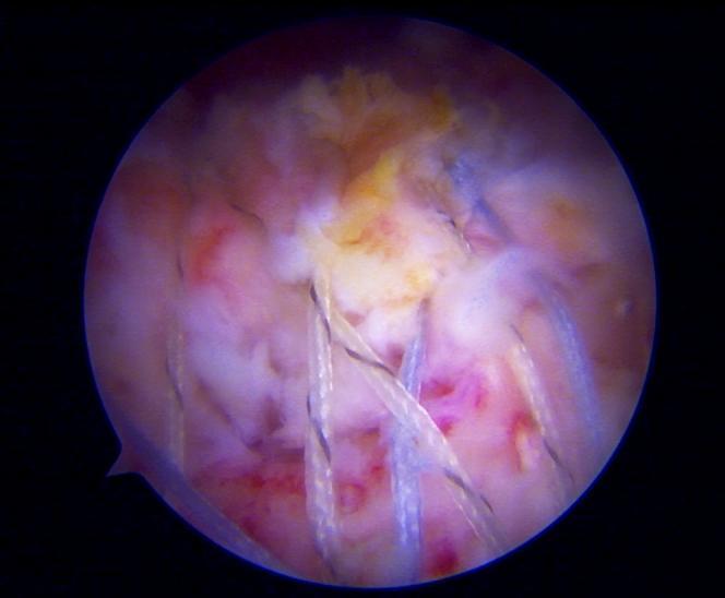
This arthroscopic image provides a subacromial view of a right shoulder, demonstrating the surgical repair of a greater tuberosity avulsion fracture using a double-row suture bridge fixation technique. The visual field shows multiple high-strength, braided suture strands (white and blue) crisscrossing over the repaired fracture site to create a compressive 'bridge' over the bone fragment. These sutures are organized into medial and lateral rows, facilitating anatomical reduction and stabilization of the rotator cuff tendon back to its footprint on the humerus. The underlying tissue exhibits a mix of white tendinous fibers and pink-to-yellow mottled bone and soft tissue, indicating vascularized repair sites. This technique is commonly employed in orthopedic surgery for massive rotator cuff tears or displaced greater tuberosity fractures to maximize the contact area between the tendon/bone fragment and the humeral footprint, thereby enhancing healing potential through stable internal fixation.
Rotator Cuff Tears: Evaluation, Management & Arthroscopic Repair
KNRUHS Paper 4 Theory - 15 Marks Structured Answer
INTRODUCTION (1 mark)
I. CLASSIFICATION (2 marks)
A. By Depth
| Type | Description |
|---|---|
| Partial thickness | Does not extend through full thickness of tendon |
| Full thickness | Complete breach through tendon; classified by size |
- Articular surface (undersurface) - most common; seen in throwing athletes and internal impingement
- Bursal surface - associated with extrinsic impingement
- Interstitial (intratendinous) - concealed within substance
B. By Size - Cofield Classification (Full-Thickness)
| Size | Dimension |
|---|---|
| Small | < 1 cm |
| Medium | 1 - <3 cm |
| Large | 3 - <5 cm |
| Massive | ≥ 5 cm |
C. Fatty Infiltration - Goutallier Classification (MRI/CT)
| Grade | Description |
|---|---|
| 0 | Normal muscle |
| 1 | Muscle contains some fatty streaks |
| 2 | Fatty infiltration < muscle tissue (<50%) |
| 3 | Fatty infiltration = muscle tissue (50%) |
| 4 | Fatty infiltration > muscle tissue (>50%) |
Key point: Grade ≥3 fatty infiltration predicts poor repair outcomes
D. By Onset
- Acute traumatic - sudden injury, good tissue quality, repair within 3 weeks (outcomes significantly worse if delayed >4 months)
- Chronic degenerative - insidious, poor tissue quality, fatty infiltration
II. CLINICAL EVALUATION (3 marks)
A. History
- Age: >40 years; peak incidence 5th-6th decade
- Dominant complaint: Night pain (pathognomonic for rotator cuff pathology), painful arc (60-120°), weakness overhead
- Onset: Most patients cannot recall a specific traumatic incident
- Pain referred to area of deltoid insertion; pain distal to elbow suggests cervical radiculopathy
B. Physical Examination - Special Tests
| Test | Technique | Significance |
|---|---|---|
| Neer's sign | Forced forward flexion with arm pronated, examiner stabilizes scapula | Positive if pain - subacromial impingement (sensitivity 72%) |
| Hawkins-Kennedy | Arm at 90° flexion, internal rotation - produces impingement | More sensitive than Neer (sensitivity 79%) |
| Painful arc | Active abduction 60-120° painful | Subacromial pathology |
| Neer's injection test | Pain abolished by lidocaine injection into subacromial space | Confirms subacromial origin |
| Test | Technique | Significance |
|---|---|---|
| Jobe/Empty can test | 90° abduction, 30° forward flexion, thumb down (pronated) - resist abduction | Supraspinatus tear/weakness |
| Full can test | Same position but thumb up - resist abduction | Better specificity than empty can |
| Drop arm test | Patient unable to maintain 90° abduction | Full-thickness, large supraspinatus tear (specificity ~97%) |
| Test | Technique | Significance |
|---|---|---|
| External rotation lag sign | Passive ER at 0° abduction, patient cannot maintain ER | Infraspinatus tear |
| Hornblower's sign | 90° abduction, ER; patient cannot externally rotate against resistance | Teres minor tear / massive posterosuperior tear |
| Test | Technique | Significance |
|---|---|---|
| Lift-off test (Gerber) | Hand behind back, lift hand away from lumbar spine | Subscapularis tear |
| Belly-press test | Press hand into abdomen while keeping wrist straight | Anterior subscapularis tear |
| Bear-hug test | Hand on opposite shoulder, examiner pulls hand away | Subscapularis tear (most sensitive) |
| IR lag sign | Passive IR at 20°, patient cannot maintain | Full-thickness subscapularis tear |
C. Investigations
| Modality | Role | Details |
|---|---|---|
| Plain X-ray | Baseline | Superior migration of humeral head (>7 mm critical) = massive tear; acromion type (Bigliani I/II/III); ACJ arthritis |
| Ultrasound | Dynamic, first-line | Sensitivity ~79-100%, specificity ~94-99% for full-thickness tears; operator-dependent; identifies partial tears, tendinopathy; allows dynamic assessment and guided injections |
| MRI (Gold standard) | Definitive assessment | Tear size, retraction, fatty infiltration (Goutallier grade), muscle atrophy; acromion morphology; concomitant pathology (SLAP, biceps, labrum) |
| MR arthrography | Partial tears | Superior sensitivity for articular-sided partial tears and SLAP lesions |
| CT arthrogram | MRI contraindication | Excellent detail; used for surgical planning in massive tears |
III. MANAGEMENT (2 marks)
A. Non-Operative Treatment
- Activity modification - avoid overhead activities
- NSAIDs - anti-inflammatory (note: preoperative NSAIDs predict inferior long-term outcome after repair)
- Physiotherapy - strengthening periscapular muscles, rotator cuff rehabilitation, posterior capsule stretching
- Subacromial corticosteroid injection - for symptomatic relief (max 3 injections per year)
- PRP injection - emerging evidence; may improve non-operative outcomes
B. Operative Indications
- Acute traumatic full-thickness tears (especially in young, active patients)
- Failed conservative treatment >3-6 months
- Young patient (<63 years) with documented full-thickness tear
- Tear involving the rotator cable (anterior cable involvement)
- Progressive weakness or functional deterioration
- Professional/overhead athletes
IV. ARTHROSCOPIC REPAIR - TECHNIQUES (4 marks)
Principles of Arthroscopic Rotator Cuff Repair
- Provides superior visualization of glenohumeral joint and subacromial space
- Allows treatment of concomitant pathology (biceps, labrum, SLAP, ACJ)
- Lower morbidity, faster recovery versus open repair
- Equivalent clinical outcomes to open repair for all tear sizes
Patient Positioning
- Beach chair position - easier orientation, reduced neurovascular risk
- Lateral decubitus - better visualization for posterior tears, better traction
Portal Placement
- Posterior portal (primary viewing) - 2 cm inferior and 1 cm medial to posterolateral acromion
- Anterior portal - medial to bicipital groove
- Lateral portal - 3 cm distal to lateral acromion (working portal for supraspinatus repair)
- Accessory portals as required
Steps of Arthroscopic Repair
- Assess glenohumeral joint, biceps, labrum, articular-surface cuff pathology
- Identify tear: size, retraction, tissue quality
- Thorough bursectomy to visualize entire footprint
- Assess bursal surface tear extent
- Type III (hooked) acromion: routine acromioplasty
- RCT 2022 (Woodmass et al.) - long-term outcomes: no difference between repair with vs without acromioplasty in full-thickness tears
- Current trend: selective, not routine
- Release of coracohumeral ligament
- Posterior interval slide (for posterior supraspinatus and infraspinatus)
- Anterior interval slide (between supraspinatus and subscapularis)
- Release of capsule at glenoid insertion (glenoid margin incision)
- Critical: Do not dissect below teres minor (axillary nerve at risk in quadrangular space; suprascapular nerve at spinoglenoid notch)
- Decorticate greater tuberosity footprint with a shaver
- Create bleeding cancellous bone to enhance biological healing
Single-Row Repair
- Anchors placed in a single row along lateral aspect of greater tuberosity footprint
- Simple or mattress sutures through cuff to anchors
- Restores ~74% of footprint width
- Advantage: Simpler, faster, equivalent clinical outcomes to double-row in many studies
Double-Row Repair
- Medial row anchors: Placed at articular margin; mattress sutures through medial tendon edge
- Lateral row anchors: Placed at lateral footprint; simple sutures
- Restores 100% of native footprint area
- Better biomechanical strength and footprint contact
- Suture-bridge (transosseous equivalent - TOE) technique: Medial anchor sutures passed through cuff and tied, then suture limbs are passed over cuff and fixed to lateral knotless anchors - creates a "bridging" compression effect
- Biomechanically, double-row is superior (greater contact pressure, footprint area)
- Clinically: Multiple RCTs show equivalent functional outcomes for small-medium tears
- Double-row may be superior for large and massive tears (>3 cm) with regard to healing rates
- Retear rates: Double-row and suture-bridge have lower structural failure rates for large tears
Biceps Tendon Management
- Long head of biceps (LHB) pathology is common with RCT
- Options: tenotomy (quick recovery, older/low-demand) vs tenodesis (better cosmesis, younger/active)
- Biceps tenodesis increasingly preferred in patients <55 years
V. MASSIVE AND IRREPARABLE TEARS - OPTIONS (1.5 marks)
Definitions
- Massive tear: ≥5 cm, typically involves ≥2 tendons
- Irreparable tear: Cannot be brought to the footprint without excessive tension; Goutallier grade ≥3 fatty infiltration; severe muscle atrophy
Surgical Options for Irreparable Tears
- Latissimus dorsi transfer - for irreparable posterosuperior tears (infraspinatus/teres minor); contraindicated if subscapularis torn (loses humeral head centering)
- Pectoralis major transfer - for irreparable subscapularis tears
- Lower trapezius transfer - recent advance; better biomechanical alignment for external rotation restoration
- Introduced by Mihata et al. (2012)
- Fascia lata autograft or dermal allograft bridged from superior glenoid to greater tuberosity
- Acts as a static superior restraint, preventing superior migration
- Restores glenohumeral kinematics without requiring rotator cuff tissue
- Recent advance: Biceps tendon rerouting (LHB left attached proximally and distally, rerouted to GT anchor) as humeral head depressor - avoids graft donor site morbidity
- Biodegradable subacromial balloon injected arthroscopically
- Mechanically depresses humeral head, reduces superior migration
- Provides temporary pain relief (maintained up to 12-24 months until resorption)
- Emerging evidence for pseudoparalytic shoulder
- Definitive solution for massive irreparable tears with cuff tear arthropathy (Hamada/Neer classification)
- Deltoid substitutes for deficient rotator cuff
- Currently recommended for patients ≥55 years with low to moderate demands
- Newer literature supports use in younger active patients
VI. RECENT ADVANCES (2 marks)
1. Biological Augmentation
| Method | Details |
|---|---|
| Platelet-Rich Plasma (PRP) | Growth factors (PDGF, TGF-β, VEGF, IGF) applied at repair site; mixed evidence - some RCTs show improved structural healing, others no benefit; no clear consensus |
| Stem Cell Therapy | Mesenchymal stem cells (MSC) - significant improvements in healing time and tendon integrity in multiple studies; routes: direct injection, scaffold-seeded delivery |
| Extracellular Matrix (ECM) Scaffolds | Human dermis, porcine small intestinal submucosa, equine pericardium - used as onlay augmentation for large/massive tears; FDA-approved products include GraftJacket, Restore patch, CuffPatch |
| Bioinductive collagen implant | Bovine collagen scaffold (e.g., Regeneten) induces new tissue formation over partial tears; prospective registry data (Bushnell et al., 2021) shows promising 1-year outcomes |
2. Arthroscopic Technology Advances
- 3D visualization systems - improved spatial orientation
- Robotic-assisted arthroscopy - in development
- Fluorescence imaging - assess tissue vascularity at repair site
- Intraoperative ultrasound - confirm repair completeness
3. Suture Anchor Evolution
- From metal anchors (titanium) to bioabsorbable anchors (PEEK, PLLA, β-TCP)
- All-suture anchors - smaller footprint, less cortical disruption, lower revision complication
- Knotless anchors - simplify arthroscopic technique, reduce knot-related complications
4. Repair Construct Evolution
- Transosseous equivalent (TOE) technique - maximizes footprint compression
- Knotless suture bridge - reduced construct bulk
- Rip-stop technique - additional mattress suture prevents medial suture cut-through in poor tissue
5. Decision-Making Tools
- MRI-based footprint mapping - predict repairability preoperatively
- Tear pattern classification (Gerber, Collin) - guides tendon transfer selection for irreparable tears
- Dynamic ultrasound - assessment of cable integrity and tear pattern
VII. REHABILITATION PROTOCOLS (0.5 marks)
VIII. COMPLICATIONS (0.5 marks)
| Complication | Comment |
|---|---|
| Re-tear | Most common long-term complication; rate 11-94% depending on tear size |
| Stiffness/Adhesive capsulitis | Avoid excessive immobilization |
| Infection | Rare (<1%); ceramic implants may have lower infection risk |
| Axillary/suprascapular nerve injury | During mobilization (avoid below teres minor) |
| Anchor failure | Poor bone quality, osteoporosis |
| Failed repair/Irreparable re-tear | Salvage: RTSA |
SUMMARY TABLE - Examiner's Key Points
| Aspect | High-yield Fact |
|---|---|
| Most common special test | Hawkins-Kennedy (most sensitive); Drop arm (most specific for full-thickness) |
| Gold standard imaging | MRI (tear size, Goutallier grade, retraction) |
| Best bearing option in young | Arthroscopic double-row/suture bridge repair |
| Irreparable tear gold standard | SCR (young) / RTSA (>55 years, CTA) |
| Acute traumatic tear timing | Repair within 3 weeks - best outcomes |
| Fatty infiltration cutoff | Grade ≥3 = poor repair prognosis |
| Osteolysis threshold for PE wear | >0.1 mm/year (not relevant to RC - but note fat infiltration at 3 years = moderate, 5 years = severe) |
| Most popular new advance | SCR with dermal allograft / LHB rerouting for irreparable tears |
| Biological augmentation | ECM scaffolds, MSCs, PRP - mixed results; most promising: bioinductive collagen implant |
| Acromioplasty | Long-term RCT: no difference with vs without acromioplasty in full-thickness repair |


How many will you give me limb salvage surgery 10 marks knruhs theory ms ortho
Your Notes - Marking Assessment
What you have written (honest evaluation):
| Section | Your Coverage | Quality | Marks Likely |
|---|---|---|---|
| Definition | Good - oncological clearance, margins, avoid amputation | Correct | ✓ |
| Goals of LSS | Good - primary goal, sacrifice NV if needed, optimal limb characteristics | Good | ✓ |
| Reconstruction techniques (overview) | Listed 4 types briefly | Superficial - no detail | Partial |
| PreOp planning & imaging | MRI gold std, CT, PET, angiography | Good | ✓ |
| Surgical principles | En-bloc resection, tumor capsule, plastic surgery for soft tissue | Good | ✓ |
| Prosthetic reconstruction | Endoprosthesis, modular, custom, expandable | Good | ✓ |
| LSS Advantages/Disadvantages | 4 each, listed well | Good | ✓ |
| Biological reconstruction | Autograft, allograft, recycled - adv/disadv | Good | ✓ |
| Hybrid construct | Present with adv/disadv | Good | ✓ |
| Arthrodesis | Brief, adequate | Adequate | ✓ |
| Rotationplasty | Present, brief | Adequate | ✓ |
| Complications | Early and late listed | Adequate | ✓ |
- No Enneking staging / MST staging - examiner WILL expect this
- No indications and contraindications properly structured
- No specific tumor examples (osteosarcoma, Ewing's, etc.)
- No comparison with amputation (functional outcomes data)
- Flap coverage / vascular reconstruction thin
- Rehabilitation details absent
- Outcomes data / MSTS score not mentioned
COMPLETE MODEL ANSWER - Limb Salvage Surgery (10 Marks)
INTRODUCTION / DEFINITION (0.5 marks)
INDICATIONS AND CONTRAINDICATIONS (1 mark)
- Primary malignant bone tumors (osteosarcoma - most common, Ewing's sarcoma, chondrosarcoma)
- High-grade soft tissue sarcomas
- Aggressive benign tumors (Giant Cell Tumor - recurrent/aggressive)
- Metastatic disease with good prognosis (renal, breast, thyroid)
- Neurovascular bundle encasement (major vessels/nerves) - not just proximity
- Pathological fracture through tumor (contamination of entire compartment)
- Infection at operative site
- Inability to achieve adequate surgical margins
- Tumor extent that precludes functional reconstruction
- Patient preference / poor compliance
- Skeletally immature patient (expandable prosthesis has changed this)
- Major vessel involvement (now addressed with vascular reconstruction)
PREOPERATIVE EVALUATION (1 mark)
Staging - Enneking Staging System (Surgical Staging System - SSS)
| Stage | Grade | Site | Metastasis |
|---|---|---|---|
| IA | Low (G1) | Intracompartmental (T1) | None (M0) |
| IB | Low (G1) | Extracompartmental (T2) | None (M0) |
| IIA | High (G2) | Intracompartmental (T1) | None (M0) |
| IIB | High (G2) | Extracompartmental (T2) | None (M0) |
| III | Any grade | Any site | Metastases (M1) |
Imaging Protocol
- MRI (Gold Standard) - extent of soft tissue involvement, pseudocapsule, skip lesions, neurovascular proximity, intramedullary extent; defines resection margins
- CT scan - cortical destruction, matrix calcification, pulmonary metastases
- PET-CT / Bone scan - rule out systemic metastases, multifocal disease, skip lesions
- Angiography (selective) - neurovascular involvement, feeding vessel identification, pre-embolization for hypervascular tumors
Biopsy Principles
- Biopsy MUST be performed in the operating center that will do the definitive surgery
- Core needle biopsy preferred (Trucut) - less contamination than open biopsy
- Biopsy tract included in resection specimen (must lie in the surgical field)
- Poorly planned biopsy is the most preventable cause of unnecessary amputation
GOALS OF LSS (0.5 marks)
- Primary goal: Oncological clearance - tumor resection takes priority over reconstruction
- Wide en-bloc excision with negative surgical margins
- Sacrifice NV bundles if required for oncological clearance
- Reconstruct defect to restore function
- Functional (painless, stable, allows ADL)
- Cosmetically acceptable
- Durable long-term
MULTIMODAL TREATMENT (0.5 marks)
- Reduces tumor volume, treats micrometastases
- Allows histological assessment of chemotherapy response (Huvos grade - predictor of survival)
- Grade III/IV response (>90% necrosis) = good prognosis
- Converts borderline resectable to resectable
SURGICAL PRINCIPLES (1 mark)
En-bloc Resection
- Tumor capsule integrity must be maintained at all times
- Wide margin: normal tissue cuff surrounding tumor on all sides
- Soft tissue defect managed with plastic surgery (rotational/free flap)
- Defect size does NOT compromise tumor resection - oncological margins not sacrificed for reconstruction convenience
Margin Classification (Enneking)
| Margin Type | Plane of Dissection | Risk of Local Recurrence |
|---|---|---|
| Intralesional | Through tumor | Very high |
| Marginal | Reactive zone / pseudocapsule | High |
| Wide | Normal tissue cuff | Low |
| Radical | Entire compartment | Very low |
RECONSTRUCTION METHODS (3 marks)
Factors Influencing Choice
- Defect size and location (diaphyseal vs. epiphyseal vs. periarticular)
- Joint involvement
- Patient age and growth potential (skeletal maturity)
- Available resources and surgeon expertise
- Soft tissue coverage available
- Prognosis (life expectancy)
1. Prosthetic (Endoprosthetic) Reconstruction - Most Common
| Type | Indication | Features |
|---|---|---|
| Modular megaprosthesis | Standard; periarticular tumors | Adjustable length intraoperatively; most popular |
| Custom / Patient-specific | Irregular bones (scapula, pelvis, spine) | Designed from CT/MRI; maintains oncological margins |
| Expandable prosthesis | Skeletally immature children | Non-invasive magnetic lengthening (Stanmore MUTARS, FITBONE); avoids leg length discrepancy |
2. Biological (Osseous) Reconstruction
| Type | Source | Best for |
|---|---|---|
| Autograft (fibula, iliac crest) | Patient's own bone - small gaps | Small defects; free vascularized fibula for intercalary defects |
| Allograft | Cadaveric large bone | Large segmental/intercalary defects; osteoarticular reconstructions |
| Recycled/Devitalized autograft | Resected tumor bone - cleaned and sterilized (irradiation, autoclaving, pasteurization) | Reimplanted after tumor cells destroyed |
3. Hybrid Construct (Allograft-Prosthetic Composite - APC)
- Combines mechanical prosthesis with biological tissue (allograft)
- Example: Allograft-prosthetic composite for proximal femur/humerus
- Prosthesis provides immediate stability; allograft allows soft tissue/tendon reattachment
4. Arthrodesis (Fusion)
- Surgical fusion after tumor resection
- Durable, permanent, no wear or loosening
- Suitable for manual laborers, young active patients where prosthetic longevity is concern
- Disadvantage: Loss of joint mobility (significant functional limitation for hip/knee)
- Best for: Knee, ankle, shoulder (better function than flail joint)
5. Rotationplasty (Van Nes Procedure)
- Resection of distal femur/knee with 180° rotation of the lower limb
- Ankle joint acts as a biological knee joint after rotation
- Patient fitted with an external below-knee prosthesis
- Excellent functional outcomes in children, athletes
- Best indication: Distal femur / proximal tibia tumors in young children where growth plates must be spared
- Psychologically challenging (appearance) but functionally superior to above-knee amputation
6. Soft Tissue Reconstruction
- Rotational flaps (gastrocnemius, vastus lateralis) - local muscle coverage
- Free flaps (latissimus dorsi, rectus abdominis) - for large defects; requires microvascular anastomosis
- Plastic surgery collaboration is mandatory for complex soft tissue defects
COMPLICATIONS (1 mark)
Early Complications
| Complication | Notes |
|---|---|
| Infection / wound breakdown | Most devastating; rate 3-10%; deep infection often requires implant removal |
| Wound healing problems | Due to prior chemotherapy, radiation, poor vascularity |
| Neurovascular injury | During dissection; planned sacrifice if encased |
| Severe cases → Amputation | If margins not achieved or catastrophic infection |
Late Complications
| Complication | Notes |
|---|---|
| Local tumor recurrence | Most important; ~5-10% with wide margins; requires re-excision or amputation |
| Implant failure / Aseptic loosening | Metal fatigue, loosening at bone-implant interface |
| Graft fracture / non-union | Biological reconstructions; risk increases with radiation therapy |
| Leg length discrepancy | Especially in children; addressed with expandable prosthesis |
| Periprosthetic fracture | Especially at stem tips in megaprostheses |
OUTCOMES AND COMPARISON WITH AMPUTATION (0.5 marks)
- Pain, function, emotional acceptance, hand positioning/gait, lifting strength, walking ability
- 5-year survival: Equivalent between LSS and amputation for osteosarcoma (80-90% for localized disease with chemotherapy)
- Functional outcomes: LSS significantly superior on MSTS score
- Local recurrence: LSS ~5%, amputation ~2% - slightly higher but no difference in overall survival
- Quality of life: LSS superior - preserved body image, no phantom pain, better psychosocial outcomes
Marks Allocation Guide for Examiner
| Section | Marks |
|---|---|
| Definition + Goals | 0.5 |
| Indications / Contraindications + Staging | 1.0 |
| Preoperative workup (imaging + biopsy principles) | 1.0 |
| Surgical principles (en-bloc, margins) | 1.0 |
| Reconstruction methods (all 5-6 with adv/disadv) | 3.0 |
| Multimodal treatment / Neoadjuvant chemotherapy | 0.5 |
| Complications | 1.0 |
| Outcomes + comparison with amputation | 1.0 |
| Total | 10 |