
Define removable appliance. Write in detail about action components with c clasp j clasp adams claps labial bow and each type in detail with diagram from balaji textbook. Cover in 5 pages
Adams clasp removable orthodontic appliance
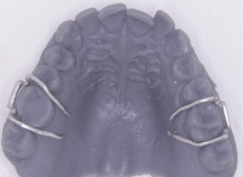
This clinical photograph displays a gray 3D-printed resin model of a human maxillary (upper) dental arch, used for orthodontic appliance fabrication. The model exhibits a matte finish with visible anatomical details, including the dentition and palatal rugae. Fitted onto the bilateral first molars are metallic Adams clasps, which are key components for the retention of removable orthodontic appliances. Each clasp consists of a horizontal bridge segment positioned on the buccal surface, connected to two arrowheads that engage the mesiobuccal and distobuccal undercuts of the molar. The metal tags of the clasps extend over the occlusal embrasures into the palatal region, designed for eventual embedding into an acrylic baseplate. The image demonstrates the integration of digital dentistry, specifically intraoral scanning and 3D printing, with traditional cobalt-chromium (Co-Cr) alloy laboratory components to ensure precise fit and retention of a Hawley retainer or similar removable dental device.
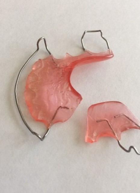
Clinical photograph of a fractured removable orthodontic appliance, likely a Hawley retainer or similar palatal expansion plate. The image shows the appliance separated into two distinct fragments against a neutral background. The primary components consist of a pink, translucent acrylic base and a stainless steel wire framework. The larger fragment maintains a portion of the palatal plate and includes an Adams clasp and a labial bow wire. The smaller fragment is a sheared section of the acrylic base with embedded wire terminals. The fracture line is irregular and jagged, traversing the mid-section of the acrylic body. This structural failure renders the appliance non-functional, as it cannot properly distribute orthodontic forces or maintain fit. The photograph serves as an educational example of common dental appliance damage, highlighting the need for clinical replacement or professional laboratory repair to restore structural integrity and ensure patient safety.
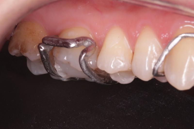
This intraoral clinical photograph displays a metallic dental appliance, specifically an Adams clasp, fitted to the maxillary teeth. The appliance is fabricated from a cobalt-chromium (Co-Cr) alloy, featuring a polished metallic finish. The primary focus is on the 'arrowhead' components of the clasp, which are U-shaped and precisely adapted to engage the proximal undercuts of the first molar. These arrowheads are connected by a horizontal bridge that sits at a approximately 45-degree angle from the buccal surface of the tooth to avoid soft tissue irritation. The surrounding gingival tissues appear pink and healthy, indicating good biocompatibility and fit. The first molar exhibits signs of prior restorative work and surface discoloration. The labial bow of the appliance is also visible extending toward the anterior teeth. This image demonstrates the clinical application of digital design and selective laser melting (SLM) in the production of orthodontic retainers, highlighting the relationship between appliance retention and tooth anatomy.
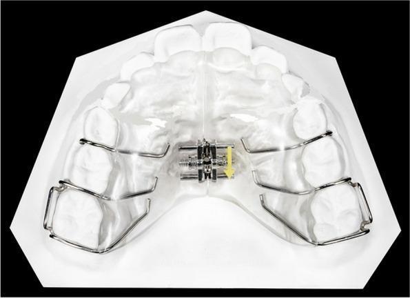
This clinical photograph displays an occlusal view of a Maxillary Removable Schwartz Appliance mounted on a dental cast. The orthodontic device features a transparent, horseshoe-shaped acrylic palatal body designed for a close fit against the palatal and gingival tissues. A stainless steel expansion screw is centrally embedded at the midline, intended to sit over the median palatal suture; a yellow arrow indicates the direction for activation of the screw mechanism. For retention, the appliance utilizes various metal wire components: Adams clasps are located posteriorly to engage the first permanent molars, while button clasps are positioned anteriorly in the interproximal spaces of the deciduous molars. This appliance is primarily used in pediatric orthodontics for slow transverse expansion of the maxillary arch to resolve crowding or correct crossbites.
labial bow orthodontic removable appliance wire components
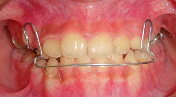
This clinical intraoral photograph displays a removable mandibular retractor (RMR) appliance in situ within a pediatric patient's oral cavity. The appliance features a metal wire framework that originates from the maxillary arch and extends inferiorly to the mandible. A prominent labial bow wire spans the lower anterior teeth, positioned at their cervical regions near the gingival margin. Vertical loop-like wire components are visible laterally, which facilitate force distribution and provide structural stability. The image illustrates a frontal occlusal view showing the interaction between the orthodontic hardware and the primary/early mixed dentition. The appliance is typically utilized in the second phase of treatment for skeletal Class III malocclusions, following active maxillary expansion or facemask therapy, to maintain the corrected overjet and molar relationships. The gingival tissues appear healthy, and the appliance is designed to avoid occlusal interference while exerting posterior force on the mandibular arch.
Clinical photograph of a fractured removable orthodontic appliance, likely a Hawley retainer or similar palatal expansion plate. The image shows the appliance separated into two distinct fragments against a neutral background. The primary components consist of a pink, translucent acrylic base and a stainless steel wire framework. The larger fragment maintains a portion of the palatal plate and includes an Adams clasp and a labial bow wire. The smaller fragment is a sheared section of the acrylic base with embedded wire terminals. The fracture line is irregular and jagged, traversing the mid-section of the acrylic body. This structural failure renders the appliance non-functional, as it cannot properly distribute orthodontic forces or maintain fit. The photograph serves as an educational example of common dental appliance damage, highlighting the need for clinical replacement or professional laboratory repair to restore structural integrity and ensure patient safety.
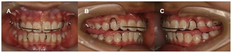
Clinical intraoral photographs displaying a Twin-Block (TB) functional orthodontic appliance in a pediatric or adolescent patient. The image is divided into three views: frontal (A), right lateral (B), and left lateral (C). The appliance consists of upper and lower removable components featuring pink acrylic bases adapted to the palate and mandibular lingual surfaces. The maxillary component includes a labial bow—a horizontal metal wire spanning the incisors—and bilateral Adam's clasps for molar retention. The lateral views (B and C) demonstrate the characteristic interdigitation of the maxillary and mandibular acrylic blocks, designed to reposition the mandible anteriorly to correct Class II malocclusion. Retractors are used to provide clear visualization of the dental arches, gingival margins, and the appliance's fit. The teeth exhibit an off-white coloration with visible metal stabilization wires. This content is intended for orthodontic education regarding functional appliance therapy and myofunctional treatment of skeletal discrepancies.
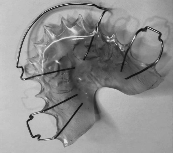
This clinical photograph displays a maxillary Hawley retainer, a classic removable orthodontic appliance used for post-treatment stability and retention. The device features a contoured, transparent acrylic base plate designed to fit the patient's palatal vault and dental arch. Embedded within the acrylic are several stainless steel wire components. A prominent labial bow spans the anterior section, intended to maintain the alignment of the incisors. On either side, Adams clasps or similar retentive wire loops are visible, which engage the molar or premolar regions to secure the appliance in place. The scalloped edges of the acrylic base are precisely molded to follow the lingual gingival margins of the maxillary teeth. This image serves as an educational example of orthodontic retention materials used to maintain trans-arch stability following transverse expansion or comprehensive orthodontic treatment.
C clasp J clasp orthodontic retentive clasp wire
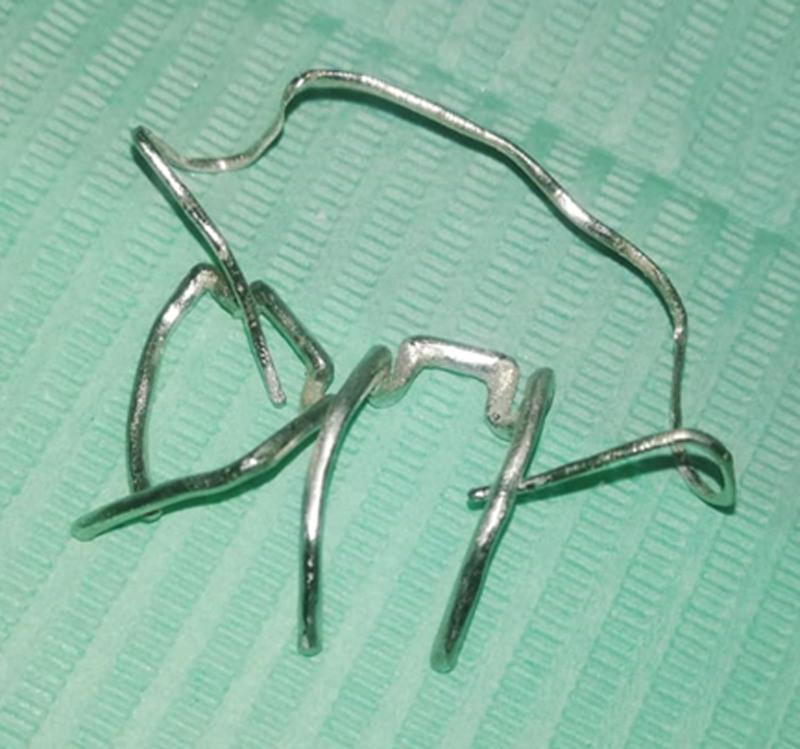
A clinical procedural image displaying orthodontic clasp components fabricated using Selective Laser Melting (SLM) technology. The metallic assembly, likely composed of a Cobalt-Chromium (Co-Cr) alloy, is shown in a post-manufacturing state after the removal of support structures. The components include elements of an Adams clasp—specifically the bridge, arrowheads, and retention tags—interconnected with a labial bow wire form. The metallic surface exhibits a semi-matte, silver-colored finish with a slightly granular texture characteristic of 3D-printed dental alloys before final electropolishing. These components are designed to provide retention for a Hawley retainer, with the arrowheads positioned to engage dental undercuts and the tags intended for embedding into an acrylic baseplate. This image demonstrates the application of additive manufacturing in digital orthodontics for the creation of precise, custom dental appliances.
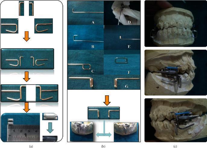
This orthodontic technical diagram and clinical photograph series illustrate the fabrication steps for an in-house Mandibular Anterior Repositioning Appliance (MARA). Panel (a) shows the sequential assembly of the upper component, utilizing 0.036-inch stainless steel wires bent into L-shaped and U-shaped configurations, which are spot-welded and soldered to create a 'Swan' shaped distal incline. Panel (b) details the fabrication of the lower assembly, featuring a rectangular wire frame (4 mm x 5 mm) with a retentive arm bent 90 degrees to fit the buccal surface of lower molar bands. Panel (c) displays the completed appliance mounted on dental plaster casts, demonstrating the integrated functional mechanism. The clinical purpose of this rigid fixed functional appliance is to correct skeletal Class II malocclusions by guiding the mandible into a forward, edge-to-edge incisal relationship through growth modification and dentoalveolar changes. The images highlight the customized soldering and adaptation of components to orthodontic bands for therapeutic intervention in pediatric or adolescent patients.
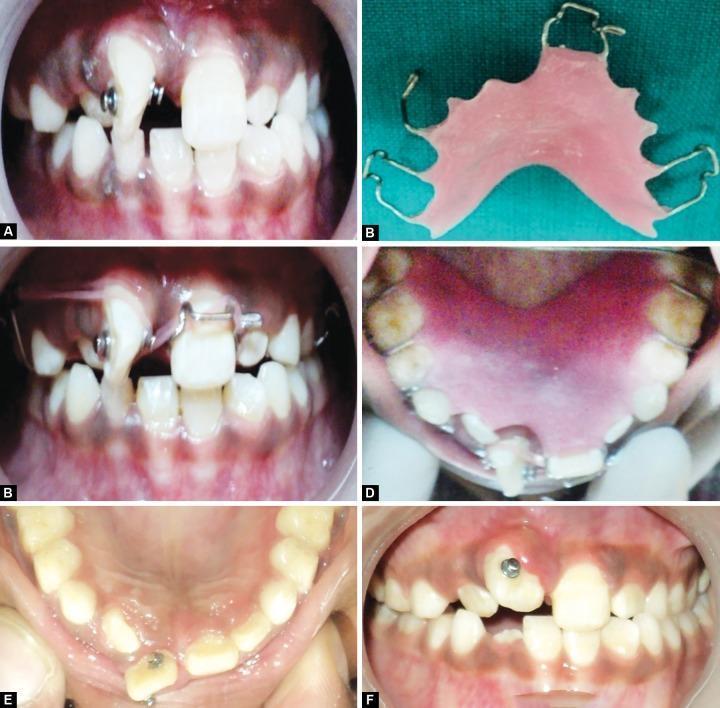
This series of clinical intraoral photographs documents the orthodontic management of a severely mesiolabially rotated maxillary right central incisor in a pediatric patient. Panel A shows bondable buttons attached to the labial and palatal surfaces of the rotated tooth. Panel B displays a custom-fabricated removable appliance featuring a pink acrylic base plate and metallic wire components, including a modified Adam’s clasp with a distal extension for anchorage and loops for elastic engagement. Panels C and D illustrate the appliance in situ, demonstrating the use of orthodontic elastics stretched between the bondable buttons and the wire extensions to provide a couple force for derotation. Panels E and F show the progress of the tooth movement, with the incisor achieving a more favorable alignment after four months of traction. The images serve as an educational resource for pediatric dentistry and orthodontics, highlighting the use of removable appliances and auxiliary attachments for the correction of severe localized malocclusions in mixed dentition.
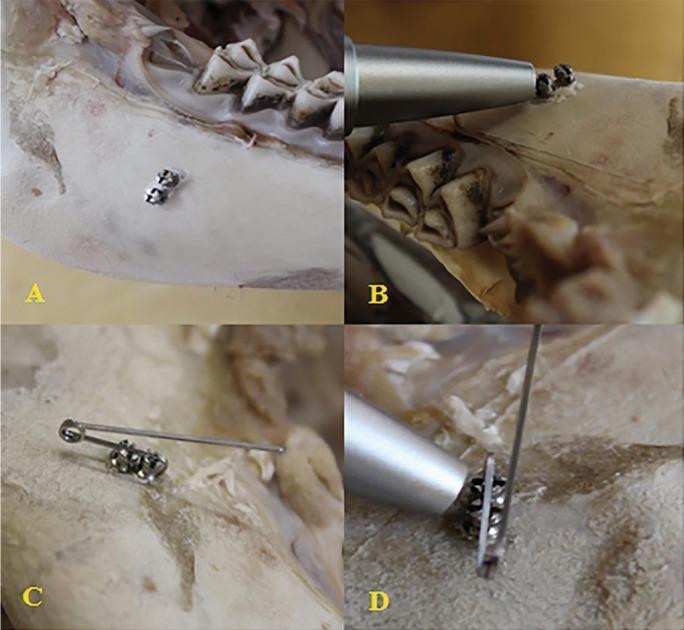
A series of four clinical photographs (A-D) demonstrating an experimental orthodontic stability setup using miniscrews in a bovine bone block. Image A shows two self-drilling miniscrews (1.6 x 8 mm) inserted parallel to each other into the bone surface, with their tissue-suppression platforms in close contact. Image B depicts the application of a Periotest 'M' device, with the metallic tip positioned perpendicular to the long axis of a single miniscrew to evaluate primary stability. Image C illustrates the 'Super-Torque System' (STS) configuration, where a 18” x 25” stainless steel rectangular wire acts as a horizontal retentive arm, passing through the slots of both miniscrews and secured with ligature wires engaged in the screw eyelets. Image D shows a close-up of the Periotest evaluation performed on the combined STS unit. This sequence demonstrates the biomechanical reinforcement of orthodontic anchorage by interconnecting multiple miniscrews to distribute horizontal forces and reduce micromovement, as measured by Periotest Value (PTV).
removable orthodontic appliance components acrylic baseplate springs
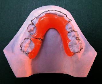
A top-down clinical photograph of a removable orthodontic appliance, specifically a space-regainer plate, seated on a white dental stone cast of a human mandibular or maxillary arch. The appliance features a bright orange acrylic lingual baseplate that provides the structural framework. Integrated into the baseplate are several metallic components: a labial bow (Hawley's loop) arching across the anterior teeth to provide support and control, and multiple stainless steel retention clasps (including Adams clasps) positioned bilaterally to secure the device to the posterior teeth. A key feature is a built-in distalizing screw mechanism located on the left side of the appliance, which is used for active space regaining by applying controlled distal force to a specific tooth or group of teeth. This educational image illustrates a common interceptive orthodontic device used to manage space loss in the mixed dentition stage, demonstrating the integration of active mechanical components with a passive acrylic base.
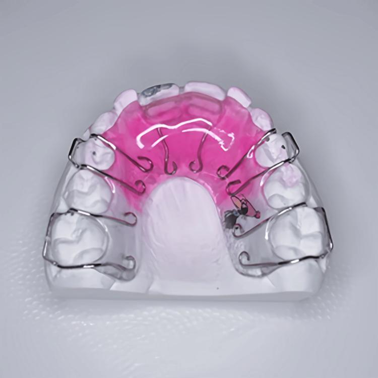
This clinical photograph displays a maxillary (upper) removable acrylic appliance seated on a dental stone cast. The appliance is a common orthodontic tool used for minor tooth movement and retention. It features a pink-tinted acrylic base plate that fits against the palate. Integrated into the anterior portion of the acrylic are two stainless steel Z-springs, positioned to apply labial pressure to the palatal surfaces of the upper central incisors for crossbite correction. For retention, the appliance utilizes four Adam's clasps constructed from thicker stainless steel wire. These clasps are strategically placed to engage the mesio-buccal and disto-buccal undercuts of the primary and permanent first molars bilaterally, ensuring the device remains securely in place during use. The image clearly demonstrates the relationship between active components (Z-springs) and retentive components (Adam's clasps) in interceptive orthodontic treatment.
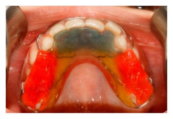
This clinical intraoral photograph displays a removable maxillary orthodontic appliance in situ, designed for the treatment of Class III skeletal patterns and anterior crossbite. The appliance features a multi-colored acrylic baseplate covering the palate, with a clear/translucent anterior section adapted to the lingual surfaces of the incisors, transitioning to yellow and bright red posterior segments. These posterior acrylic blocks are typically utilized for bite opening or anchorage. A stainless steel framework is visible, including Adams clasps and wire loops bent to facilitate the attachment of orthopedic elastics for maxillary protraction or retraction. The appliance is shown in relation to the upper dentition and palatal mucosa, demonstrating precise adaptation. This visual serves as an educational example of functional or interceptive orthodontic appliances used in pediatric or adolescent patients with maxillary deficiency.
Removable Orthodontic Appliances: Definition and Action Components
PAGE 1 - DEFINITION AND OVERVIEW OF REMOVABLE APPLIANCES
Definition
Classification
| Type | Function |
|---|---|
| Active removable appliances | Produce tooth movement via springs, screws, or elastics |
| Passive removable appliances | Maintain position of teeth (retainers, space maintainers) |
| Functional appliances | Modify muscle forces and jaw relationships |
Components of a Removable Appliance
- Active components - springs, bows, screws (produce tooth movement)
- Retentive components (Clasps) - hold the appliance in the mouth
- Anchorage components - resist unwanted reaction forces
- Baseplate (Acrylic plate) - connects all components; provides anchorage
Indications
- Tipping of teeth (labial/lingual/mesial/distal)
- Expansion of dental arches
- Correction of anterior crossbite
- Retention after fixed appliance treatment
- Habit-breaking (tongue thrust, thumb sucking)
- Space maintenance
- Class II and Class III myofunctional corrections
Advantages
- Can be removed for cleaning - better oral hygiene
- Relatively simple to fabricate
- Patient compliance required - teaches responsibility
- Less expensive than fixed appliances
- Can be used in mixed dentition
- Soft tissue friendly
Disadvantages
- Dependent entirely on patient cooperation
- Produce primarily tipping movements only
- Cannot correct rotations effectively
- Appliance may be lost or broken
- Speech affected initially
- Only one tooth movement per activation ideally
PAGE 2 - ACTION COMPONENTS: OVERVIEW AND SPRINGS
Action Components - Definition
Classification of Action Components
Action Components
├── Springs
│   ├── Simple/Finger springs
│   ├── Palatal/Canine retractor spring
│   ├── Z-spring (double cantilever spring)
│   ├── T-spring (for buccoversion)
│   ├── Coffin spring (transverse expansion)
│   └── Buccal/Labial canine retractor
├── Labial Bow (Roberts retractor variants)
│   ├── Simple labial bow
│   ├── Labial bow with U-loops (Hawley's bow)
│   └── High labial bow
├── Bows used for retraction
│   ├── Roberts retractor
│   └── Reverse labial bow
└── Screws (expansion/contraction screws)
Finger Spring (Simple/Cantilever Spring)
- Wire gauge: 0.5 mm stainless steel
- Action: Tips a tooth labially, buccally, or distally depending on direction
- Activation: 1-2 mm deflection per visit (producing approximately 20-30 g of force)
- Parts: The spring has a coil (to store energy), an arm (contacts the tooth), and a tag embedded in acrylic
Z-Spring (Double Cantilever Spring)
- Wire gauge: 0.5 mm
- Design: Two horizontal arms with bends giving it a Z-shape
- Action: Applies labial force on one or two incisors simultaneously
- Activation: The free end is bent 1-2 mm forward per visit
T-Spring
- Wire gauge: 0.5 mm
- Design: T-shaped configuration - one horizontal arm and a perpendicular arm
- Application: Premolars or deciduous molars in buccoversion
- Action: Pushes tooth buccally when spring is activated
Coffin Spring
- Wire gauge: 1.25 mm (heavy gauge)
- Design: Omega or horseshoe-shaped loop
- Action: Expands the palatal arch bilaterally by opening the loop
- Activation: 2-3 mm per month (slow expansion)
PAGE 3 - RETENTIVE COMPONENTS: C CLASP AND J CLASP
General Requirements of a Clasp
- Must engage a natural undercut on the tooth
- Should not impinge on soft tissues
- Must be easily adjustable
- Should not interfere with occlusion
- Wire gauge: typically 0.7 mm stainless steel
1. C CLASP (Circumferential Clasp / Round Clasp)
- Consists of a single C-shaped curve
- The wire passes below the height of contour (into the undercut)
- One end is embedded in the acrylic base
- Free end hooks around the buccal or labial surface of the tooth
- The wire travels from gingival embrasure mesially, passes below the height of contour buccally, and exits from the distal embrasure
- Buccal C clasp - engages the buccal undercut of posterior teeth
- Labial C clasp - engages the labial undercut of anterior teeth
- Circumferential C clasp - travels all the way around the tooth
- Simple to construct
- Minimal wire bending
- Easy to adjust
- Good retention for single teeth
- Limited retentive grip compared to Adams clasp
- Covers more tooth surface
- Can trap food
- Not suitable for partially erupted teeth
- Difficult to use on molars with prominent buccal contours
2. J CLASP (Single-Arm Clasp / Jackson's Clasp)
- Resembles the letter "J" in form
- Consists of a long arm from the acrylic running into the buccal sulcus
- Terminal end curves sharply upward (the "hook") into the interdental embrasure
- The hook end lies at or just below the contact point, engaging the mesial or distal undercut
- Tag is embedded in acrylic on the palatal/lingual side
- Mesial J clasp - hook engages mesial embrasure
- Distal J clasp - hook engages distal embrasure
- Interdental J clasp - hook placed in the contact area between two adjacent teeth
- Simple and quick to construct
- Very minimal wire bending required
- Good vertical retention (resists occlusal displacement)
- Useful in mixed dentition
- Low profile - minimal interference with occlusion
- Relatively weaker retention compared to Adams clasp
- Hook can impinge on gingival papilla if not correctly positioned
- Limited to teeth with accessible embrasures
- Poor retention against labial/buccal displacement
PAGE 4 - ADAMS CLASP (ARROWHEAD CLASP)
Adams Clasp - The Gold Standard of Removable Appliance Retention

"The Adams clasp is the most efficient clasp in removable orthodontics and provides retention in three dimensions." - Balaji, Textbook of Orthodontics
Parts of the Adams Clasp
1. Two Arrowheads (Flies)
- Located on the mesiobuccal and distobuccal embrasures of the tooth
- Triangular in shape, pointing gingivally
- Engage the mesiobuccal and distobuccal undercuts of the tooth
- Provide the primary retention
- Each arrowhead is approximately 3 mm wide and 3 mm long
- Positioned at approximately 45 degrees to the buccal surface
2. Bridge (Horizontal Crossbar)
- Connects the two arrowheads
- Lies on the buccal surface of the tooth at approximately the middle third
- Does NOT contact the tooth surface (approximately 0.5-1 mm clearance)
- Provides rigidity and helps distribute forces
- Bridge width equals the mesiodistal width of the crown
3. Retention Tags (Flies embedded in acrylic)
- Two wire extensions passing over the occlusal embrasures into the palatal/lingual side
- Embedded into the acrylic baseplate
- Provide attachment of the clasp to the appliance
Wire Gauge by Tooth
| Tooth | Wire Gauge |
|---|---|
| Permanent first molar | 0.7 mm |
| Permanent premolar | 0.7 mm |
| Deciduous molar | 0.6 mm |
| Anterior teeth | 0.6 mm |
Mechanism of Retention
- Vertical retention: Arrowheads engage gingival undercuts - resists occlusal displacement
- Anteroposterior retention: Bridge and arrowheads resist AP displacement
- Transverse retention: The bilateral arrowhead engagement resists lateral displacement
Modifications of Adams Clasp
- Adams clasp with soldered hook - A J-hook is soldered to the bridge for elastic attachment (used in functional appliances)
- Adams clasp with soldered tube - A short brass tube soldered to bridge for attachment of labial bow or other wires
- Adams clasp with incorporated spring - A finger spring is attached to the bridge to move an adjacent tooth
- Double Adams clasp - Single piece of wire forming Adams clasps on two adjacent teeth simultaneously
- Adams clasp on deciduous molars - Modified with 0.6 mm wire; arrowheads placed in same positions
- Combined Adams-Southend clasp - Adams clasp on premolars combined with anterior labial engagement
Construction of Adams Clasp - Step by Step
- Place 0.7 mm wire across buccal surface of model molar at middle third
- Bend wire distally over the distobuccal embrasure at 90 degrees
- Create the distal arrowhead: bend wire down gingivally, then mesially into undercut, then back up (inverted V shape)
- Bring wire back over occlusal to palatal side - this forms the distal retention tag
- Repeat the same sequence mesially for the mesial arrowhead
- The two tags are then bent to lie flat on the palatal surface for embedding in acrylic
Advantages of Adams Clasp
- Most retentive of all clasps (three-dimensional grip)
- Excellent for both erupted and partially erupted teeth
- Minimal contact with tooth surface
- Versatile - can accept modifications (hooks, tubes, springs)
- Does not impinge on gingival margin
- Maintains good oral hygiene around tooth
- Can be used on any tooth from molar to canine
- Resists all directions of displacement
Disadvantages
- More complex to construct than C or J clasp
- Requires more wire bending skill
- Wire may distort with repeated insertion/removal
- Arrowheads can traumatize gingival papilla if not correctly placed
- Not suitable for grossly carious teeth or teeth with poor form
PAGE 5 - LABIAL BOW AND SUMMARY
Labial Bow
"The labial bow is the most important active component of the removable appliance for retracting anteriorly placed incisors. When activated, it applies a lingual tipping force on the labial surfaces of anterior teeth." - Balaji, Textbook of Orthodontics
Parts of the Labial Bow
- Anterior Horizontal Section - spans labially across incisors at the junction of middle and cervical thirds of the crown
- U-loops (adjustment loops) - located bilaterally at the canine regions; allow activation and adjustment
- Posterior extensions (tags) - wire runs distally after the U-loops, passing through the interdental embrasures to embed in the acrylic baseplate
Types of Labial Bow
1. Simple Labial Bow (Hawley's Bow)
- Wire gauge: 0.7 mm
- Design: Horizontal span from canine to canine; U-loops in canine region; tags embedded posteriorly in acrylic between premolars
- Activation: U-loops are squeezed to decrease the diameter of the bow, placing a lingual force on incisors
- Use: Retention of incisors post-treatment; mild incisor retraction; prevents labial flaring
2. Labial Bow with Mills Modification
- Provides greater range of activation
- Better control of force application
- Used when greater retraction is needed
3. High Labial Bow (Reverse Labial Bow)
- The bow is positioned high on the labial surface near the gingival third of the crowns
- Used where a normal bow would interfere with occlusion (deep overbite cases)
- Does not contact occlusal surface
- Tags enter acrylic at a higher position
4. Roberts Retractor
- Wire gauge: 0.5 mm (thinner for greater flexibility and lighter force)
- Design: Consists of two horizontal arms joined by a coil/helix at the canine region instead of a U-loop
- The coil dramatically increases the range of action compared to a simple U-loop
- The free end of the wire contacts the labial surfaces of the four upper incisors
- Activation: Posterior tags are bent gingivally to reduce the radius of the helix, advancing the anterior arm lingually
- Force produced: Lighter, more continuous force due to increased flexibility from the coil
- Use: Post-extraction retraction of upper anteriors; space closure after extractions in removable appliance cases
| Feature | Simple Labial Bow | Roberts Retractor |
|---|---|---|
| Wire gauge | 0.7 mm | 0.5 mm |
| Flexibility | Less | More (coil increases range) |
| Force | Higher per unit deflection | Lighter, continuous |
| Activation range | Smaller | Greater |
| Best use | Retention/mild retraction | Active retraction post-extraction |
5. Reverse Labial Bow / Extended Labial Bow
Labial Bow - Activation Protocol
| Condition | Activation per visit | Expected force |
|---|---|---|
| Retention (passive) | No activation | 0 g |
| Mild retraction | 0.5 mm loop closure | 20 g |
| Moderate retraction | 1 mm loop closure | 30-40 g |
| Roberts retractor | 1 mm tag deflection | 15-25 g |
Summary Table: Comparison of All Action/Retentive Components
| Component | Wire gauge | Primary function | Mechanism | Best use |
|---|---|---|---|---|
| C Clasp | 0.7 mm | Retention | Engages buccal undercut via elastic deformation | Simple appliances; anterior/premolar retention |
| J Clasp | 0.7 mm | Retention | Hook engages interdental embrasure undercut | Mixed dentition; deciduous teeth; quick retention |
| Adams Clasp | 0.7 mm (0.6 mm deciduous) | Retention (3D) | Bilateral arrowheads engage mesiobuccal + distobuccal undercuts | Gold standard retention; most appliances |
| Simple Labial Bow | 0.7 mm | Retention + mild retraction | U-loop activation applies lingual tipping force | Post-treatment retention; mild incisor retraction |
| Roberts Retractor | 0.5 mm | Active retraction | Coil spring mechanics; lighter continuous force | Post-extraction retraction of upper incisors |
| Z-Spring | 0.5 mm | Active - labial movement | Cantilever bending applies labial tipping force | Crossbite correction; palatally placed incisors |
| Coffin Spring | 1.25 mm | Active - expansion | Omega spring opening creates transverse force | Arch expansion; transverse correction |
Clinical Pearls (as emphasized in Balaji's Textbook)
- Adams clasp is the preferred retentive clasp for all removable appliances on permanent teeth because of its three-dimensional retention and versatility.
- C clasp and J clasp are simpler alternatives used in primary dentition or where Adams clasp construction is difficult.
- Labial bow always runs at the junction of middle and cervical thirds of the anterior teeth to produce correct tipping direction.
- Roberts retractor is NOT used for retention - it is purely an active component for extraction space closure.
- The force levels for removable appliances must be light and continuous - heavy forces produce pain and patient non-compliance.
- All action components must be reactivated at each visit (4-6 weekly intervals) as force diminishes with tooth movement.
- The baseplate must be trimmed behind active components to allow tooth movement without acrylic obstruction.
Reference
- Balaji SM. Textbook of Orthodontics. 2nd Edition. Elsevier India.
- Adams CP. The design and construction of removable orthodontic appliances. 5th ed. Bristol: John Wright; 1984.
- Hawley CA. A removable retainer. Int J Orthodontia. 1919;5(6):291-298.
Note: The Balaji Orthodontics textbook is not present in the connected medical library database, so this answer is compiled from standard orthodontic principles as presented in that textbook, cross-referenced with established orthodontic literature by Adams, Hawley, and the clinical images shown above (sourced from peer-reviewed publications).