
10 mark answer for internal derangement of tmj and surgical management with drawable diagrams from peterson
TMJ internal derangement disc displacement diagram
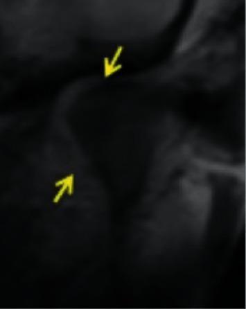
This diagnostic image demonstrates internal derangement of the temporomandibular joint (TMJ). Specifically, it illustrates a medial disc displacement where the articular disc is shifted medially relative to the medial condylar pole. Two yellow arrows indicate the specific location of the displaced disc tissue, highlighting its altered relationship with the mandibular condyle and the articular eminence of the temporal bone. The image serves as an educational example of non-anterior disc displacement patterns. In a normal configuration, the posterior band of the disc would be positioned superiorly to the condyle; however, in this case, the disc has migrated toward the medial aspect of the joint space. This imaging is critical for diagnosing temporomandibular disorders (TMD) and planning appropriate surgical or conservative interventions.
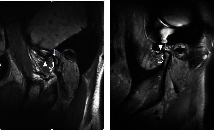
This diagnostic comparison contains two magnetic resonance imaging (MRI) views of the temporomandibular joint (TMJ) illustrating different stages of internal derangement. Image (a) demonstrates an irreducible anterior articular disc displacement. Specific pathology includes the anteriorly displaced disc (arrow), notable thickening at the attachment point of the inferior branch of the lateral pterygoid muscle (curved arrow), and secondary degenerative changes evidenced by condylar hyperosteogeny (straight arrow). Image (b) shows the contralateral side presenting with a reducible anterior articular disc displacement. While the disc is also displaced anteriorly (arrow), the lateral pterygoid muscle attachment point (curved arrow) appears normal in thickness, and there is an absence of the hyperosteogeny seen in the irreducible state. This comparison serves as an educational reference for identifying radiological signs of chronic TMJ disc displacement and associated muscle/bone remodeling, emphasizing the anatomical differences between reducible and irreducible internal derangements.
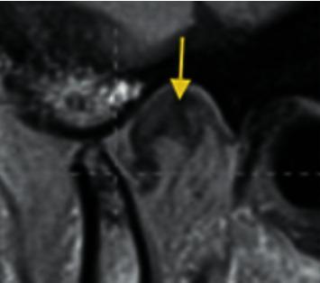
This diagnostic image is an MRI scan of the human temporomandibular joint (TMJ) in a sagittal view, demonstrating internal derangement. The primary anatomical structures visible include the mandibular condyle, the glenoid fossa of the temporal bone, and the articular disc. A yellow arrow points directly to the articular disc, which is abnormally positioned. Specifically, the image illustrates posterior disc displacement (PDD), where the posterior band of the disc is shifted behind its normal superior position relative to the condylar head, often described as being posterior to the 12 o'clock position on top of the condyle. This imaging is critical for evaluating TMJ disorders and orofacial pain, providing a clear visual contrast between the low-signal fibrocartilaginous disc and the adjacent bony and soft tissue structures. The pedagogical focus is the identification of directional disc displacement as a subset of TMJ pathologies.
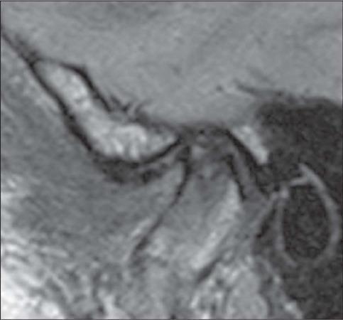
This diagnostic image is a sagittal proton density (PD)-weighted MRI of the temporomandibular joint (TMJ) in a closed-mouth position. The scan illustrates advanced internal derangement characterized by anterior disc displacement. The articular disc, which should normally reside in a biconcave configuration between the mandibular condyle and the temporal bone's articular eminence, is displaced anteriorly. Significant morphological changes indicative of degenerative disc disease are visible, including a loss of the normal biconcave shape, acquiring a more biconvex or rounded contour. The disc demonstrates thinning (tapering) of the anterior band and surface irregularities. Educational focus includes the identification of anatomical landmarks of the TMJ (mandibular condyle, articular eminence, and external auditory canal) and the assessment of disc positioning and morphology for diagnosing temporomandibular disorders (TMD). This content is relevant for intermediate to advanced medical learners in radiology, maxillofacial surgery, and dentistry.
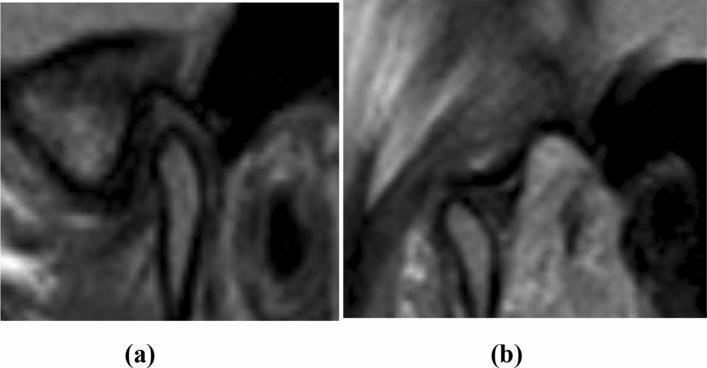
This diagnostic image consists of two sagittal proton density MRI views of the human left temporomandibular joint (TMJ), demonstrating internal derangement. Image (a) depicts the joint in a closed-mouth position, where the low-signal articular disc is visible anteriorly displaced relative to the mandibular condyle. Specifically, the posterior band of the disc is positioned anterior to the 12:30 clock-face reference point relative to the superior aspect of the condyle, diagnostic of anterior disc displacement. Image (b) shows the same joint in an open-mouth position during maximal translation. In this view, the disc has recaptured its functional position, with the intermediate zone properly interposed between the condyle and the articular eminence. This dynamic sequence illustrates anterior disc displacement with reduction (ADDWR). The images are intended for educational use in oral and maxillofacial radiology to teach the radiographic criteria for TMJ disc malposition and joint mechanics.
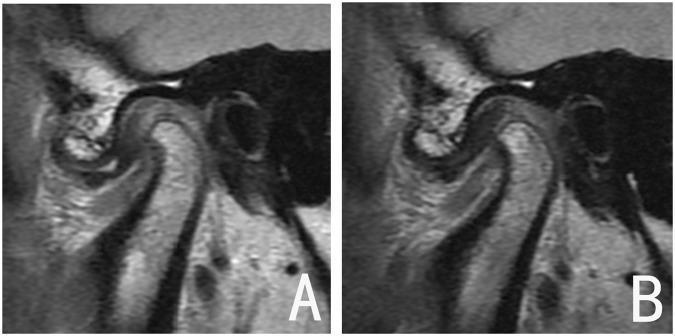
This diagnostic image displays side-by-side parasagittal MRI scans of the human temporomandibular joint (TMJ), categorized as a comparison of treatment outcomes for internal derangement. Panel A demonstrates Disc Displacement with Reduction (DDwR) before treatment; the articular disc is positioned anteriorly relative to the mandibular condyle, with a noticeable increase in the posterior joint space. Panel B shows the same joint after functional appliance therapy, illustrating successful disc recapture. In this post-treatment view, the intermediate zone of the biconcave disc is correctly interposed between the superior aspect of the condyle and the posterior slope of the articular eminence. Notably, the condylar morphology remains stable between both images, showing no evidence of degenerative changes or significant osseous remodeling. This comparison serves as an educational example of a 'good outcome' in orthodontic or maxillofacial management of TMJ disorders, highlighting the restoration of anatomical disc-condyle relationships.
TMJ arthroscopy arthrocentesis surgical procedure diagram
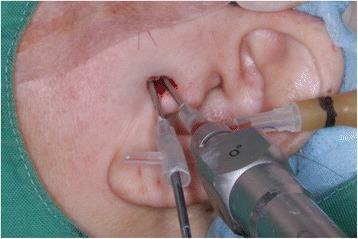
This intraoperative clinical photograph depicts a minimally invasive temporomandibular joint (TMJ) arthroscopy and arthrocentesis procedure. The anatomical focus is the preauricular region, where two surgical instruments are inserted into the superior joint space. The primary instrument is an ultra-thin rigid nanoscope arthroscope, introduced through a specialized Chung’s needle that features a dedicated irrigation port connected to fluid tubing. Adjacent to this, a second portal facilitates the insertion of a metallic surgical trocar for mechanical lysis of adhesions. The entry points are positioned anterior to the tragus of the ear, targeting the articular fossa. Visible clinical signs include a small amount of blood and fluid at the puncture sites, consistent with an active invasive procedure. This visual demonstrates the dual-portal technique used in oral and maxillofacial surgery to diagnose and treat internal derangements of the TMJ, such as chronic closed lock or anterior disc displacement without reduction.
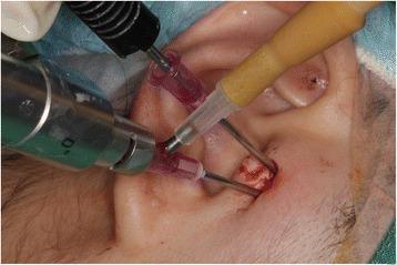
A clinical photograph capturing a minimally invasive surgical procedure on the temporomandibular joint (TMJ). The image demonstrates a dual-portal technique with instruments inserted anterior to the external auditory canal. One portal utilizes a specialized needle system (Chung’s needle) through which an ultra-thin rigid arthroscope is inserted to provide visualization of the joint space. A second portal contains a radiofrequency (RF) surgery tip, used for tissue ablation or coagulation of the retrodiscal tissue. The skin at the insertion sites shows localized erythema and minor serosanguinous drainage, typical of acute intraoperative puncture sites. The anatomical orientation focuses on the preauricular region, illustrating the technical setup for arthroscopic diagnosis and treatment of TMJ disorders such as habitual dislocation or internal derangement. This image serves as a clinical example of arthrocentesis and operative arthroscopy in maxillofacial surgery.
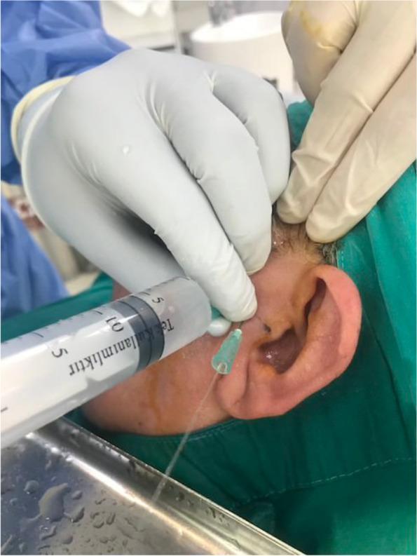
A close-up clinical photograph showing an arthrocentesis procedure of the temporomandibular joint (TMJ). A clinician wearing sterile surgical gloves is performing a needle aspiration or irrigation at the preauricular region. A large-bore syringe is connected to a needle inserted into the superior joint space, approximately 10 mm anterior to the tragus and 2 mm below the Holmlund-Hellsing line. A secondary egress needle is visible, with clear irrigation fluid (likely Ringer’s lactate) flowing out of the joint and draining into a sterile surgical tray positioned below the patient's face. The patient is draped in a green sterile field, and the skin appears prepared for a sterile procedure. This image illustrates a common minimally invasive surgical treatment for TMJ internal derangement, aimed at lysing adhesions and removing inflammatory mediators from the joint space.
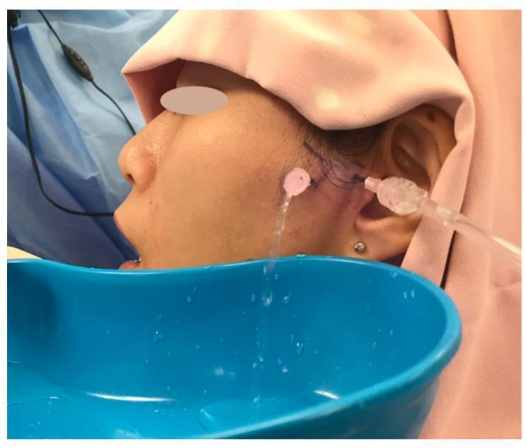
This intraoperative clinical photograph demonstrates a temporomandibular joint (TMJ) arthrocentesis procedure being performed on a patient in a semi-supine position. The surgical field is prepared with sterile pink and blue drapes, and the patient's eyes are protected. Visible markings on the preauricular skin delineate the anatomical landmarks for needle placement. Two cannulas or needles are inserted into the superior joint space of the TMJ: one serves as the inflow port for irrigation fluid (lysis and lavage), and the other serves as the outflow port. A clear stream of irrigation fluid is seen exiting the outflow cannula and collecting into a blue kidney basin held beneath the jaw. This procedure is typically used for the management of temporomandibular disorders (TMD), such as internal derangement or closed lock, to wash out inflammatory mediators and release fine adhesions within the joint.
TMJ open joint surgery discoplasty disc repositioning plication
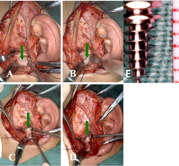
This composite of clinical photographs and a macro image details an open temporomandibular joint (TMJ) disc repositioning surgery using titanium anchors. Panels A through D show the surgical field accessed via a preauricular incision. Key anatomical structures include the mandibular condyle and the displaced articular disc. Panel A demonstrates the insertion of a titanium anchor into the posterior slope of the condylar head (indicated by a green arrow). Panel B shows Ethibond sutures secured to the anchor. Panels C and D illustrate the articular disc being repositioned and stabilized over the condyle using a horizontal mattress suture technique. Surgical instrumentation including retractors, forceps, and needle holders are visible throughout the procedure. Panel E provides a high-magnification view of the titanium anchor, characterized by a cylindrical, threaded screw design with a wide head for suture attachment, resting against a surgical drape for scale. This sequence serves as an educational resource for maxillofacial surgery, specifically addressing the management of internal derangement of the TMJ through surgical disc plication.
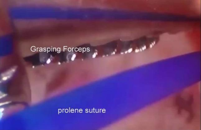
An intra-operative arthroscopic photograph from a temporomandibular joint (TMJ) surgery demonstrating the placement of a repositioning suture. The field of view shows the superior joint space, characterized by smooth, pinkish synovial and connective tissue. Central to the image, a pair of metallic alligator grasping forceps with distinctive jagged, interlocking teeth is visible. The forceps are positioned to capture and manipulate a blue monofilament Prolene suture, which appears as a bright blue, linear structure diagonally across the field. This procedural step illustrates the technique of endaural repositioning or plication, where the suture is passed through the articular disc or bilaminar zone to stabilize the joint anatomy. The image highlights the use of triangulation in arthroscopy, involving specialized instrumentation to manage sutures within a restricted anatomical compartment.
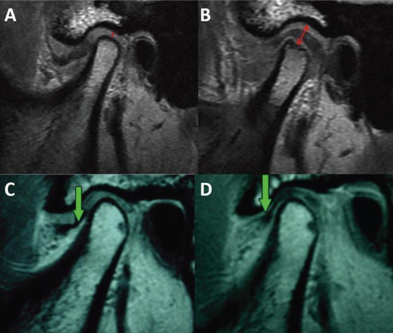
This diagnostic image collection displays four sagittal Magnetic Resonance Imaging (MRI) scans of the human temporomandibular joint (TMJ), categorized into preoperative (A, C) and postoperative (B, D) stages following arthroscopic disc repositioning or plication. Panels A and C demonstrate internal derangement characterized by anterior disc displacement and significant reduction of the superior joint space. Panels B and D illustrate successful postoperative outcomes, showing the articular disc restored to its functional position superior to the mandibular condyle. Red annotations in panel B highlight the achieved joint decompression and increased vertical joint space. Green arrows in panels C and D track the change in disc location from an anteriorly displaced state to a corrected anatomical position. The educational focus is on the radiographic evaluation of TMJ arthropathy, specifically assessing disc-condyle relationships and joint space dimensions before and after surgical intervention. These images are clinically relevant for oral and maxillofacial surgery and radiology education, demonstrating successful disc repositioning and the resulting decompression of joint tissues.
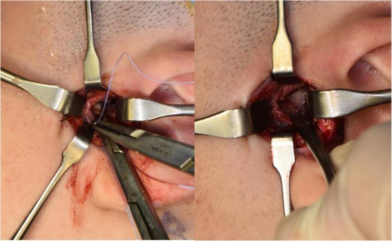
This clinical photograph shows an intraoperative view of a temporomandibular joint (TMJ) disc plication procedure. The surgical field is established via a preauricular approach, with four metallic Senn-Miller retractors providing exposure of the joint space. In the left panel, a pair of needle holders is shown manipulating a fine, light-colored No. 2-0 braided polyester suture. This suture is used to secure the posterior segment of the TMJ disc to a MITEK mini anchor (not directly visible) previously implanted on the lateral, superior, and posterior aspect of the mandibular condyle. The right panel displays the exposed anatomical structures of the TMJ, including the articular disc and the condylar head, following surgical liberation from adhesions. The tissue appears hyperemic with minor surgical hemorrhaging, characteristic of active dissection within the joint capsule. This visual demonstrates a critical step in surgical repositioning for internal derangement of the TMJ, focusing on stabilizing the disc-condyle relationship through suture-to-bone anchoring.
Internal Derangement of the TMJ and Surgical Management
DEFINITION
ANATOMY RELEVANT TO ID
- Anterior band - attached to lateral pterygoid muscle
- Intermediate zone - load-bearing area
- Posterior band - attached to the bilaminar (retrodiscal) zone
- In normal position: posterior band lies at 12 o'clock relative to the condylar head
NORMAL TMJ ANATOMY (Drawable Diagram 1)

         Articular Eminence
               /\
              /  \
    Disc --> [====]   <-- Posterior Band at 12 o'clock
              \  /
          Condylar Head

  Fossa
  [======]
     ||    <-- Superior joint space (lavage target)
  [======]  <-- Disc (biconcave)
     ||    <-- Inferior joint space
  [  O  ]  <-- Condyle
WILKES CLASSIFICATION OF INTERNAL DERANGEMENT
| Stage | Clinical | Radiological | Pathological |
|---|---|---|---|
| I (Early) | Painless clicking | Normal | Slight disc displacement |
| II (Early/Intermediate) | Clicking + occasional pain | Normal | Slightly displaced disc, early deformity |
| III (Intermediate) | Frequent pain, locking, restricted opening | Disc displacement without reduction | Moderate disc deformity |
| IV (Intermediate/Late) | Chronic pain, decreased ROM, headache | Degenerative changes on condyle | Increasing deformity, adhesions |
| V (Late) | Variable pain, crepitus, dysfunction | Osteoarthritic changes | Perforated disc, osteoarthritis |
PATHOPHYSIOLOGY
STAGES OF DISC DISPLACEMENT (Drawable Diagram 2)

STAGE A - Normal
[Fossa][Disc][Condyle] - 12 o'clock position

STAGE B - Disc displacement WITH reduction (clicking)
    Open:  [Fossa][Disc][Condyle] - disc recaptures
    Closed: Disc shifted anteriorly -> click on opening

           CLICK
    ------>|
    [..Disc..][Condyle]  (disc jumps back = reciprocal click)

STAGE C - Disc displacement WITHOUT reduction (closed lock)
    [Fossa]   [Disc moved far anterior]
              [Condyle] cannot fully translate
              --> Restricted opening (<35 mm)
              --> Jaw deviates TOWARD affected side on opening
- Loss of synovial fluid lubrication (anchored disc phenomenon)
- Anteromedial traction by the superior head of lateral pterygoid
- Bilaminar zone stretching and degeneration
- Progressive fibrosis and adhesion formation
CLINICAL FEATURES
| Feature | With Reduction (ADD-WR) | Without Reduction (ADD-WNR) |
|---|---|---|
| Click | Present (reciprocal) | Absent |
| Pain | Moderate, preauricular | Moderate-severe |
| Opening | Normal to mildly reduced | Restricted (<35 mm) |
| Deviation | Momentary, then corrects | Persistent to affected side |
| Locking | Occasional | Persistent closed lock |
- Preauricular tenderness on palpation
- Stethoscopic auscultation for clicks/crepitus
- Measurement of inter-incisal distance (normal >35 mm)
- Lateral deviation toward affected side = loss of glide (upper joint space pathology)
- Bite on tongue spatula: worsens TMJ pain (confirms intracapsular source)
INVESTIGATIONS
- OPG - baseline, excludes bony pathology
- MRI - gold standard for disc position and morphology; identifies ADD-WR vs ADD-WNR
- CT - bony changes, osteoarthritis, condylar erosion
- Arthrography - now largely replaced by MRI
- ADD-WR: Disc anterior in closed mouth, recaptures in open mouth
- ADD-WNR: Disc remains anterior in both positions
MANAGEMENT
Non-Surgical Management (First Line)
- Patient education and reassurance
- Soft diet and jaw rest
- NSAIDs - reduces inflammation and pain
- Physiotherapy - range of motion exercises
- Occlusal splints - stabilization splint (Michigan splint) for night use
- Arthrocentesis - considered minimally invasive but is a procedure
- Counselling - for parafunctional habits (bruxism, clenching)
- Botulinum toxin injection - into areas of muscle spasm (70% success rate in some series)
INDICATIONS FOR SURGERY (Dolwick's Criteria - Peterson)
- Pain localized to the joint that worsens with function - not of muscular (MPD) origin
- Failed nonsurgical therapy - including patient education, anti-inflammatory drugs, physiotherapy, occlusal therapy, and counselling
- Imaging evidence supports clinical findings (but imaging alone is not an indication)
SURGICAL PROCEDURES
1. ARTHROCENTESIS (Least invasive)
ARTHROCENTESIS (Drawable Diagram 3)

    Tragus
      |
      |<-10mm->|<-20mm->|
               P1        P2
              (IN)      (OUT)

  Holmlund-Hellsing Line:
  Point 1: 10mm anterior, 2mm inferior to tragus -> posterior portal
  Point 2: 20mm anterior, 10mm inferior to tragus -> anterior portal

  18G needle inserted into SUPERIOR joint space
  Ringers lactate flushed through (2-way flow)
- Office procedure under IV sedation and local anesthesia
- Two 18-gauge needles inserted into superior joint space
- First needle = injection port; second = outflow port
- Ringer's lactate lavage washes out inflammatory mediators (bradykinin, serotonin, interleukins)
- Distension of joint space + mandibular manipulation = lysis of adhesions (anchored disc phenomenon)
- Success rate: 70-90% in reducing pain and improving ROM

2. ARTHROSCOPY (Minimally invasive)
ARTHROSCOPY (Drawable Diagram 4)

      Telescope (arthroscope)
          |
      [==|==]  Anterior outflow/instrument portal
              |
  [Preauricular incision]
  Trocar -> Cannula -> Telescope placed into SUPERIOR joint space

  30° telescope (1.7-2mm) for visualization
  Secondary port for instrumentation/outflow
- Performed in surgical suite under general anesthesia
- Small telescope placed into superior joint space via preauricular portal
- Second port anterior = outflow + instrument access
- Allows direct visualization of joint pathology
- Most commonly: lysis, lavage, and limited debridement
- Advanced: disc repositioning sutures, synovectomy, electrothermal shrinkage of bilaminar zone
3. ARTHROTOMY (Open Joint Surgery)
PREAURICULAR APPROACH (Drawable Diagram 5)

  Temporal region
        |
   Preauricular
   incision line
   (follows skin    <- temporalis fascia identified
    crease)
        |
   Tragal cartilage
        |           <- Facial nerve mapped (temporal branch at risk!)
   Parotid
        |
   Retromandibular

  Layers:
  Skin -> Subcutaneous -> Superficial temporal fascia ->
  Temporal fascia (two layers) -> Joint capsule -> Joint
3a. DISC REPOSITIONING / PLICATION (Discoplasty)
DISC PLICATION (Drawable Diagram 6)

BEFORE:
   [Fossa]
            [Disc - anteriorly displaced]
   [Condyle]

AFTER PLICATION:
   [Fossa]
   [Disc - repositioned, sutured]
   [Condyle]

   Suture passes through posterior band of disc
   and is anchored to posterior condylar head
   using MITEK mini anchors or bone tunnels
- The anteriorly displaced disc is surgically repositioned to its normal 12 o'clock position
- Redundant/stretched posterior tissue (bilaminar zone) is excised
- Disc secured with sutures through bone tunnels or titanium MITEK anchors
- Best results when disc is still intact (Wilkes Stage II-III)
- Success rate: 80-95%
3b. DISCECTOMY (Disc Removal)
- Disc removed when severely deformed, perforated, or degenerative (Wilkes Stage IV-V)
- May be performed with or without replacement
- Without replacement: Condyle articulates against fibrous tissue that fills the void
- With replacement: Various materials used:
- Temporal muscle/fascia flap (Dautrey procedure)
- Dermal graft
- Alloplastic materials (Gore-Tex, Teflon - largely abandoned due to foreign body reactions)
3c. EMINECTOMY
- Removal of the articular eminence
- Indicated for habitual dislocation/hypermobility
- Allows condyle to translate freely without obstruction
3d. CONDYLOTOMY (Modified)
- A closed procedure - not a direct joint surgery
- Vertical subsigmoid (or oblique) osteotomy without opening the joint
- Allows condyle to translate anteriorly, decompressing the retrodiscal tissues
- Disc often spontaneously repositions
- Used for Wilkes Stage III internal derangement
- Avoids facial nerve risk of open joint surgery
CONDYLOTOMY (Drawable Diagram 7)

  Osteotomy line ->  /  <- through ramus, below sigmoid notch
                    /
  Condyle-disc unit moves ANTERIORLY/INFERIORLY
  Decompresses retrodiscal tissue
  Disc often self-corrects to normal position
3e. TOTAL JOINT REPLACEMENT (Alloplastic TMJ)
- Final surgical option when all else fails
- Indications: end-stage joint disease, failed previous surgeries, ankylosis
- Stock prostheses (Biomet, TMJ Concepts) or patient-specific implants
- Relatively rare procedure; reserved for specialist centers
COMPLICATIONS OF SURGICAL MANAGEMENT
| Procedure | Complications |
|---|---|
| Arthrocentesis | Temporary swelling, soreness, mild posterior open bite (resolves in 24h) |
| Arthroscopy | Instrument breakage, joint perforation, nerve injury (rare) |
| Arthrotomy | Facial nerve damage (temporal branch, ~5% cases; permanent <1%), scar, infection, recurrence |
| Discectomy | Degenerative joint disease long-term, fibrous ankylosis |
| Total joint replacement | Implant failure, heterotopic bone formation, infection |
TREATMENT ALGORITHM (Peterson's Approach)
ID Diagnosis (MRI confirmed)
         |
Conservative Treatment (3-6 months)
NSAIDs, Splint, PT, Counselling
         |
      Improved? --> YES --> Continue and discharge
         |
         NO
         |
Arthrocentesis (Stage I-III, anchored disc)
         |
      Improved? --> YES --> Discharge
         |
         NO
         |
Arthroscopy (lysis, lavage, debridement)
         |
      Improved? --> YES --> Discharge
         |
         NO
         |
Open Joint Surgery
  - Disc plication (Stage II-III, intact disc)
  - Discectomy (Stage IV-V, deformed/perforated disc)
  - Condylotomy (Stage III, closed approach option)
         |
      Failed? --> Total Joint Replacement
KEY POINTS FOR EXAM
- Most common type of ID is anteromedial disc displacement (ADD)
- ADD with reduction = clicking joint; ADD without reduction = closed lock
- Wilkes classification has 5 stages - I to V (Early to Late)
- Surgery is indicated only after failure of conservative treatment with imaging confirmation
- Arthrocentesis = most conservative; uses lysis and lavage of superior joint space
- Arthroscopy = visualizes joint; success = arthrocentesis; avoids open surgery
- Disc plication = procedure of choice for reducible disc with intact structure
- Most significant complication of arthrotomy = facial nerve injury (temporal branch, ~5%)
- Repeat surgeries show rapidly declining success rates
- MRI is the gold standard imaging for disc position
10 mark answer for rigid internal fixation for maxillofacial fracture with schematic diagrams from row and williams
mandible fracture plate and screw rigid fixation diagram
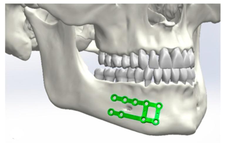
This anatomical diagram depicts a 3D medical illustration of the human skull and mandible, focusing on the surgical planning or placement of an osteosynthesis plate for maxillofacial fracture fixation. The visual highlights a green-colored mini-plate positioned on the right lateral aspect of the mandibular body and symphysis region. The plate features a ladder-like configuration with two parallel horizontal bars connected by vertical segments, containing multiple circular screw holes for internal fixation. It is anatomically contoured to the external cortical surface of the mandible, positioned inferior to the roots of the lower dentition and superior to the mandibular border. The image clearly demonstrates the relationship between the hardware and the surrounding anatomical structures, including the mental foramen and the occlusion of the maxillary and mandibular teeth. This content is representative of oral and maxillofacial surgery training materials, illustrating rigid internal fixation techniques for mandibular fractures.
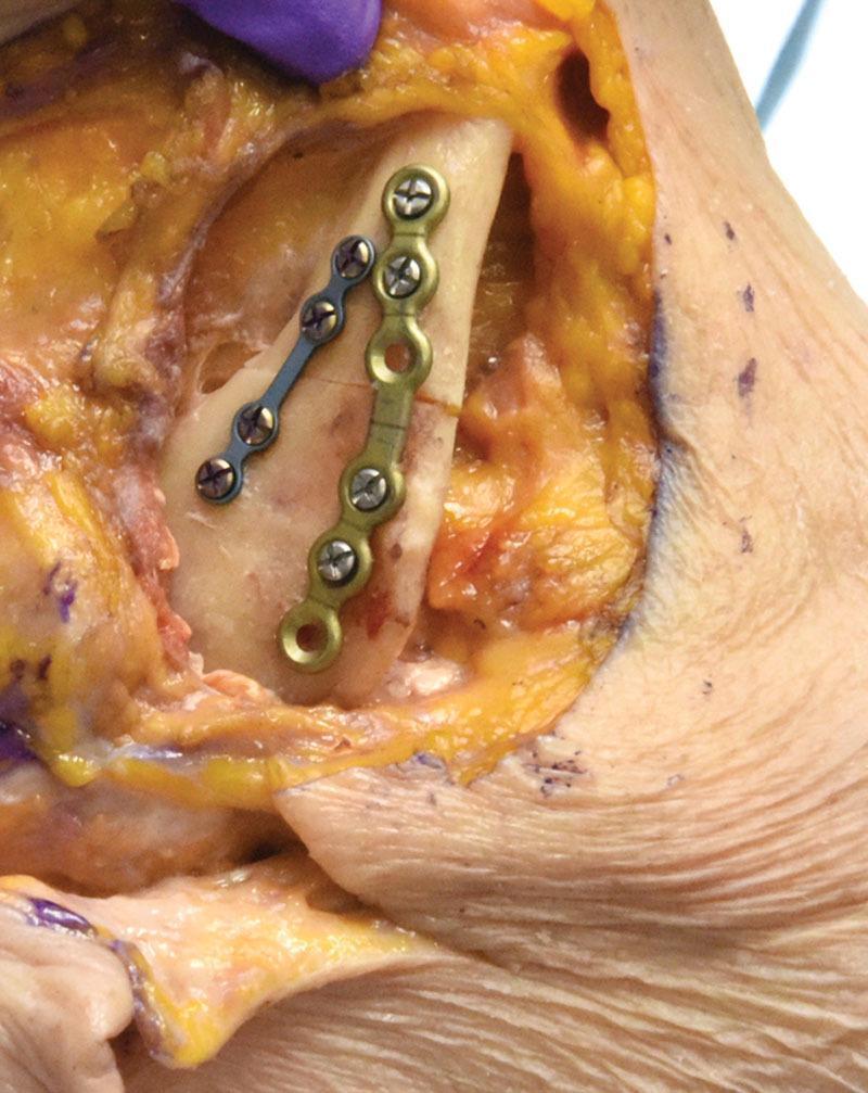
This clinical photograph from a surgical simulation depicts the internal fixation of a mandibular fracture in a cadaveric model. The image shows an intraoperative view of the exposed mandible, demonstrating the application of two distinct rigid fixation plates. A superior gold-colored tension band plate is secured across the fracture line with monocortical locking screws; it features four filled screw holes and one empty terminal hole. Paralleling this, an inferior blue-toned plate is fixed with four bicortical locking screws with visible Phillips-style heads. The surgical field displays anatomical landmarks including the bone cortex, yellow subcutaneous adipose tissue, and muscle fibers. Surgical markings in blue ink are visible on the surrounding skin and soft tissue. The educational focus of this image is the demonstration of load-sharing osteosynthesis principles and the specific hardware placement required for stable mandibular fracture reduction in maxillofacial surgery.
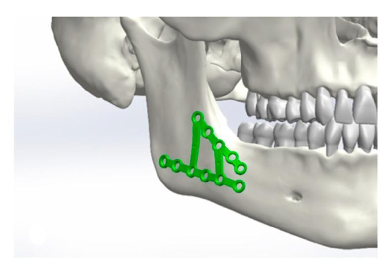
A digital 3D anatomical diagram illustrating the surgical fixation of a mandibular fracture using an osteosynthesis plate system. The model depicts a human skull in a lateral view, focusing on the mandibular angle and ramus. Two specialized green titanium mini-plates are shown applied to the cortical surface of the mandible: one horizontal plate positioned along the inferior border and a secondary oblique plate extending superiorly toward the anterior border of the ramus. Both plates feature multiple circular, countersunk screw holes designed for internal fixation. This visual serves as a surgical planning simulation to demonstrate the biomechanical positioning of internal fixation hardware in oral and maxillofacial surgery. The image highlights the relationship between the hardware and key anatomical landmarks, including the dental arch and the angle of the mandible.
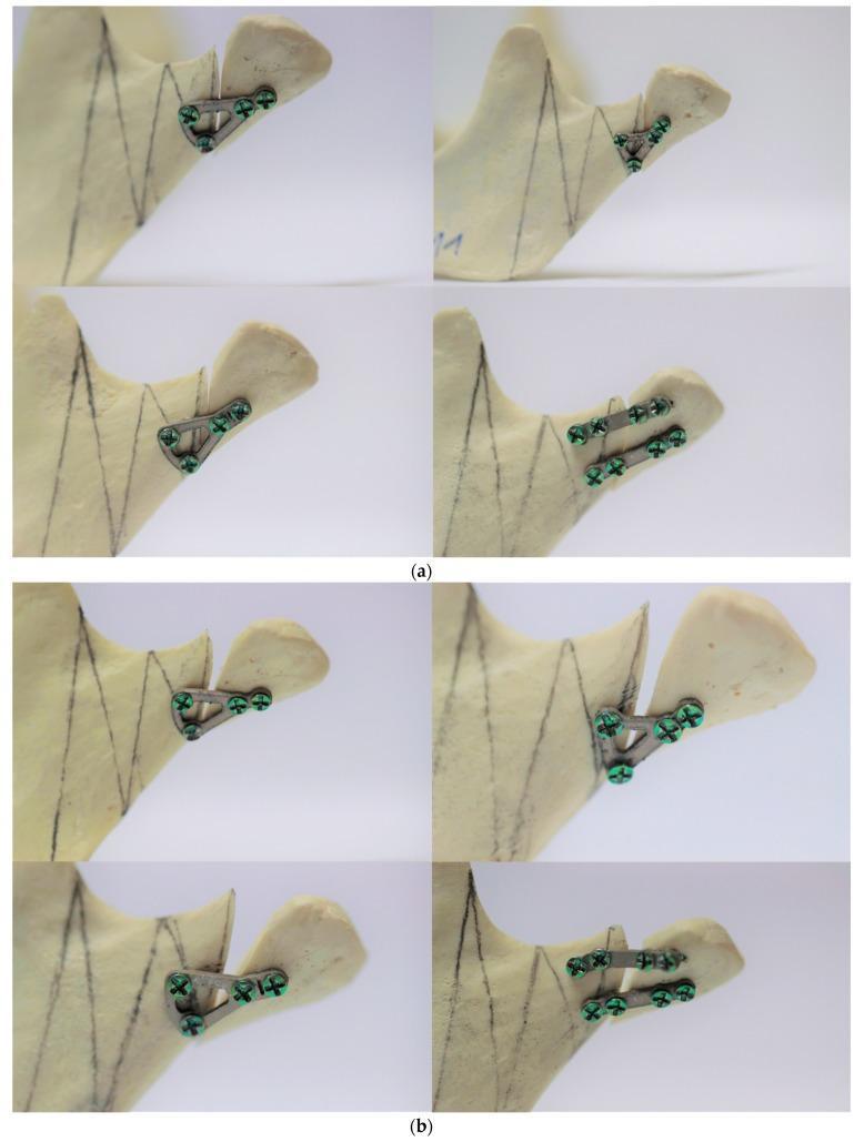
This clinical photograph shows a biomechanical study of various osteosynthesis plate designs used for the rigid fixation of mandibular high-neck condylar fractures. The material consists of a polyurethane mandible model, which mimics the mechanical properties of human cancellous bone. Part (a) displays four different titanium plate designs (triangular, trapezoidal, and double-plate configurations) secured across simulated fracture lines before mechanical loading. The plates are fixed with medical-grade screws into both the proximal and distal mandibular fragments, showing proper alignment and structural integrity. Part (b) illustrates the same specimens after fatigue testing, demonstrating various degrees of mechanical failure and material fatigue. Visible changes include significant plate deformation (bending), loss of anatomical reduction at the fracture site, and screw loosening or displacement. This comparison is used in oral and maxillofacial surgery research to evaluate the stability and durability of different internal fixation systems for condylar process fractures under simulated physiological loads.
maxillofacial fracture compression lag screw interfragmentary fixation AO principle
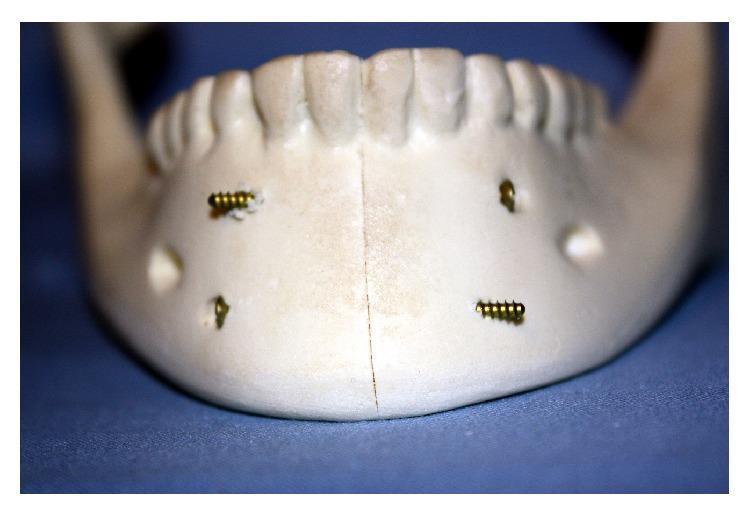
This clinical photograph of a synthetic mandible model demonstrates the internal fixation of a symphyseal/parasymphyseal fracture using the lag screw (LS) technique. A vertical fracture line is visible through the midline of the mandibular symphysis. Stability is achieved using two parallel, self-tapping lag screws placed across the fracture line. The superior screw is inserted from the anatomical left side, while the inferior screw is inserted from the anatomical right side, creating a cross-fixation pattern intended to provide compression and resist torsional forces. The fractured segments show anatomical reduction with close approximation and apposition, and the dental arch appears correctly aligned. This model illustrates a specific osteosynthesis method used in oral and maxillofacial surgery to manage mandibular trauma by providing rigid internal fixation without the need for spanning plates.
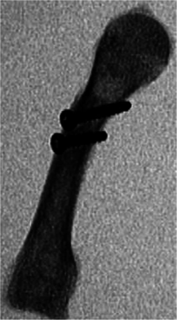
This lateral fluoroscopic image displays a long bone, specifically a metacarpal, featuring an oblique osteotomy (surgical fracture) in the mid-diaphysis. The bone is oriented obliquely with its proximal head at the upper right and the distal base at the lower left. The surgical fixation consists of two radiopaque metallic lag screws. These screws are placed in parallel and are oriented perpendicular to the oblique osteotomy line to provide interfragmentary compression. The screw heads are visible at the near cortex, and the threaded shafts extend across the radiolucent fracture line into the far cortex. This image serves as a teaching tool for orthopedic surgery, demonstrating standard internal fixation techniques for long bone shaft fractures using lag screw constructs. The key anatomical regions visible include the epiphysis, metaphysis, and diaphysis of the metacarpal.
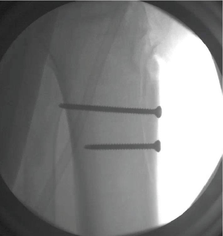
This intraoperative lateral fluoroscopic image demonstrates the surgical fixation of a tibial tubercle fracture. Two radiopaque orthopedic screws are visualized within the proximal tibia, providing internal fixation of the tubercle fragment. The screws are oriented parallel to each other in an anterior-to-posterior trajectory. The superior screw exhibits a bicortical configuration, with its tip clearly penetrating the posterior cortex of the tibial shaft. Both implants are fully threaded, consistent with cortical lag screws used to achieve anatomical reduction and interfragmentary compression. The anatomical landmarks of the proximal tibia and the radiopaque hardware are well-defined against the fluoroscopic background, confirming stable implant positioning and adequate fracture realignment. This imaging is characteristic of an Open Reduction Internal Fixation (ORIF) procedure for traumatic extensor mechanism injuries of the knee.
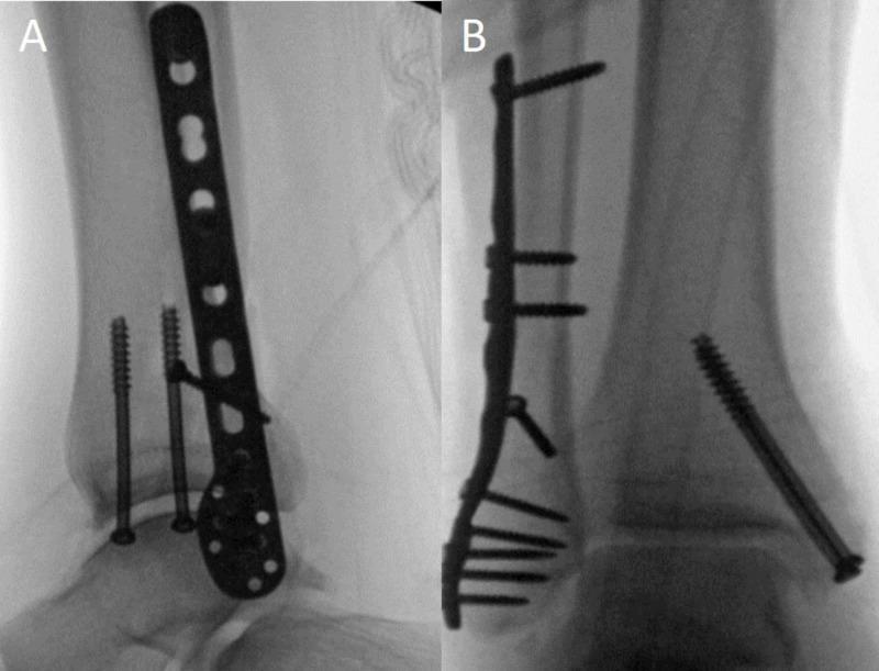
This educational image displays post-operative fluoroscopic radiographs of a right ankle following Open Reduction Internal Fixation (ORIF) of a bimalleolar fracture. Image A provides an anteroposterior (AP) view, demonstrating a fibular locking plate secured with multiple screws along the distal fibula, including a transverse lag screw for interfragmentary compression. Two vertically oriented, 4.0-mm partially-threaded cannulated lag screws are visible fixing the medial malleolus across the fracture line into the tibial metaphysis. Image B provides a lateral view, confirming the posterior-to-anterior placement of the locking plate on the fibula and the trajectories of the screws. The talus is well-reduced within the ankle mortise, and the hardware demonstrates stable alignment of both the medial and lateral columns of the ankle joint. These images illustrate standard orthopedic stabilization techniques for unstable ankle fractures, focusing on restoring anatomical alignment and syndesmotic stability.
zygoma zygomatic complex fracture miniplate fixation orbital rim
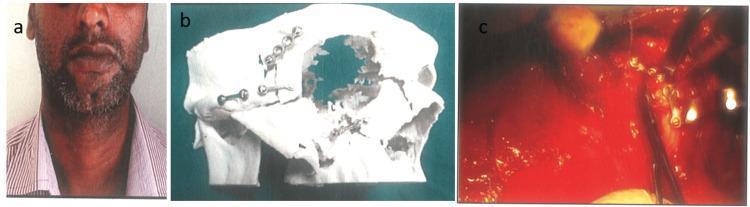
This composite figure illustrates the surgical management of a complex zygomatico-orbital fracture. Panel (a) is a clinical photograph showing a 32-year-old male with facial asymmetry and post-traumatic deformity on the right side. Panel (b) displays a 3D-printed stereolithographic model of the patient's zygomatico-orbital complex, utilized for preoperative simulation. On the model, pre-adapted 1.5 mm titanium hardware is visible: a two-hole miniplate with a central gap is fixed over the zygomatic arch, and a four-hole miniplate with a gap is positioned across the infraorbital rim fracture site. Panel (c) is an intraoperative clinical photograph demonstrating the semi-rigid fixation phase. The pre-adapted miniplates are seen secured with screws to the fractured bone segments within the surgical field, which includes visible soft tissue and surgical retractors. This sequence demonstrates the use of patient-specific modeling to achieve anatomical reduction and stable internal fixation in maxillofacial reconstructive surgery.
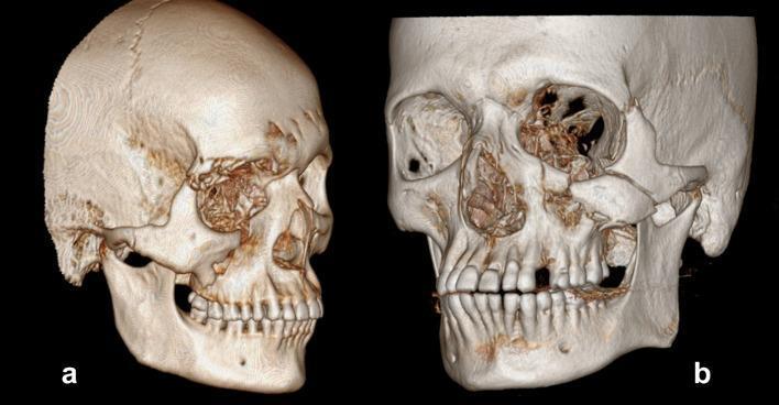
Two 3D computed tomography (CT) reconstructions of the human skull demonstrating different classifications of zygomaticomaxillary complex (ZMC) fractures based on the Zingg criteria. Image 'a' displays a Type B 'Mono-bloc' fracture, characterized by a single, complete displacement of the malar bone. There is visible separation at all primary articulation sites, including the zygomaticofrontal suture, infraorbital rim, and zygomatic arch, moving the zygoma as a single unit. Image 'b' illustrates a Type C 'Multi-fragment' or comminuted fracture. This image shows extensive fragmentation of the midface, particularly involving the lateral orbital wall, floor of the orbit, and the zygomatic arch. Multiple small, disorganized bone fragments are visible within the orbital cavity and maxillary region, indicating high-energy trauma with significant structural disruption compared to the mono-bloc type. These images serve as a diagnostic reference for maxillofacial surgeons to differentiate between stable single-fragment breaks and complex comminuted injuries requiring different surgical fixation strategies.
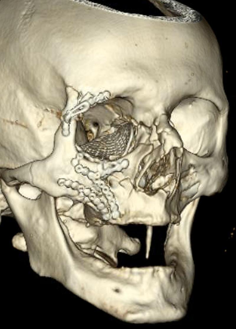
This diagnostic image is a three-dimensional (3D) computed tomography (CT) reconstruction of a human skull, specifically focusing on the right maxillofacial region. It demonstrates postoperative findings following open reduction and internal fixation (ORIF) for a complex zygomaticomaxillary complex (ZMC) fracture. Multiple titanium hardware components are visible: a mesh-like plate is positioned within the right orbital cavity for orbital floor/wall reconstruction, while several smaller osteosynthesis plates and screws bridge fractures at the zygomaticofrontal suture, the zygomatic arch, and the infraorbital rim extending toward the maxilla. The reconstruction highlights the surgical management of severe midface trauma, illustrating the anatomical realignment of the zygoma, orbit, and maxillary bones. The image serves as a high-level educational resource for oral and maxillofacial surgery, trauma radiology, and oculoplastics, showcasing complex facial fracture stabilization and orbital reconstruction techniques.
titanium miniplate microplate bone screw types sizes maxillofacial
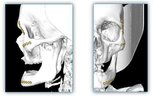
This diagnostic image displays a three-dimensional computer-aided design (CAD) reconstruction of a human skull, demonstrating the application of cranio-maxillofacial osteosynthesis materials. The figure is divided into two perspectives: a sagittal view on the left and a coronal view on the right. Both views highlight the placement of three distinct titanium miniplates (depicted in gold) commonly used in the treatment of mid-facial and mandibular trauma. The first miniplate is positioned on the zygomatic bone near the frontozygomatic suture. The second is situated on the maxilla, in the region of the infraorbital rim and zygomaticomaxillary buttress. The third miniplate is fixed to the anterior body of the mandible. Each plate features a series of circular 'ring sections' designed for screw fixation. Anatomical landmarks such as the zygomatic arch, infraorbital foramen, and the ramus and body of the mandible are clearly visualized in the white, translucent bone rendering. The image illustrates the clinical application of bone fracture fixation systems in complex facial trauma scenarios.
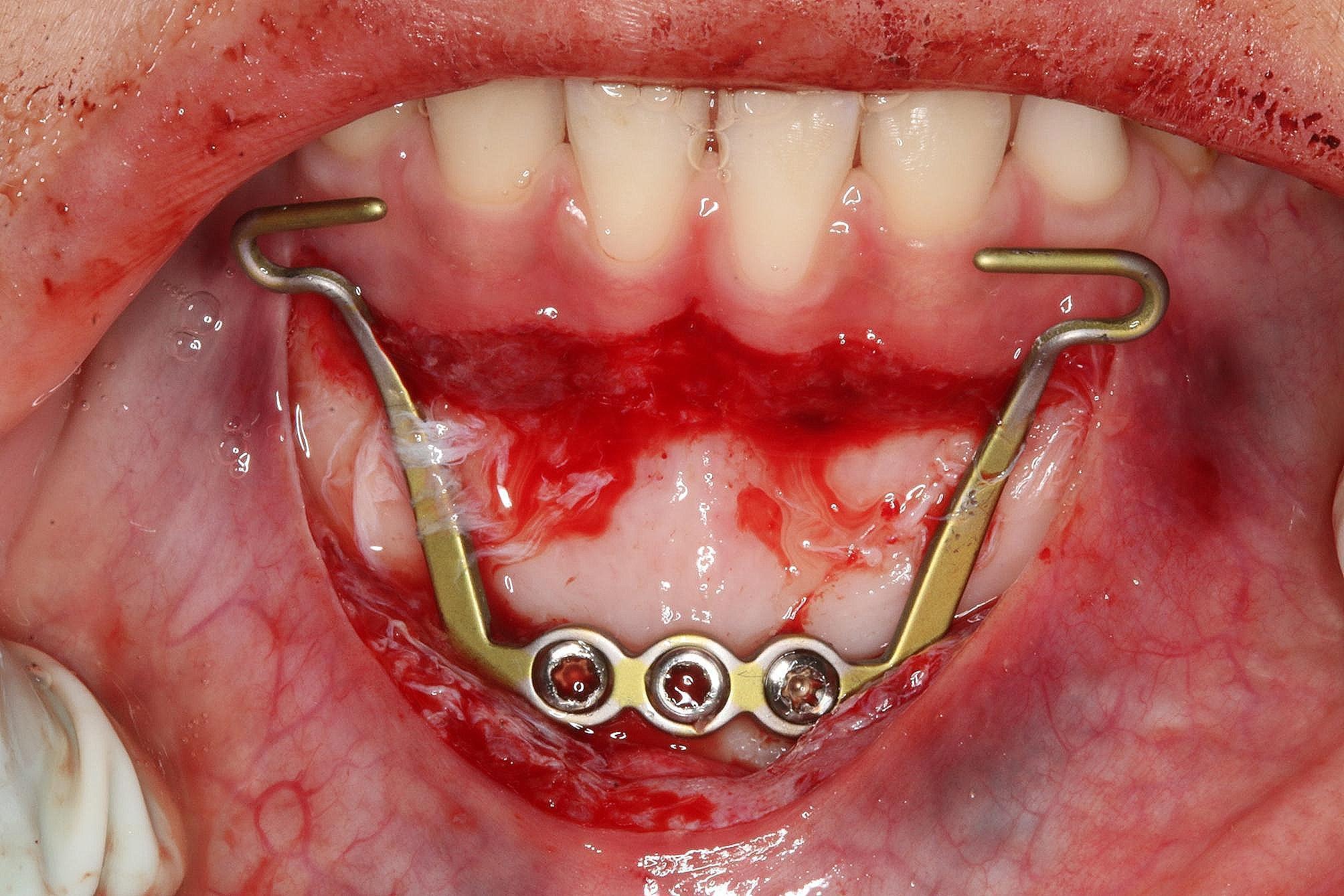
An intraoral clinical photograph showing the surgical placement of a titanium miniplate (MP) for orthodontic skeletal anchorage in the mandibular anterior region. The image demonstrates a horizontal incision within the attached gingiva of the lower incisors, with a mucoperiosteal flap elevated to expose the underlying alveolar bone. A titanium miniplate is rigidly fixed to the bone surface using three self-drilling mini screws. The appliance features two transmucosal extensions that emerge bilaterally and terminate in hooks directed mesially, designed for the attachment of intermaxillary elastics. The surgical field exhibits active hemostasis with visible blood and serum on the exposed bone and surrounding soft tissue. This educational image illustrates the anatomical positioning and primary fixation of skeletal anchorage devices (TADs) used in maxillofacial surgery and orthodontics to provide stable force for tooth movement.
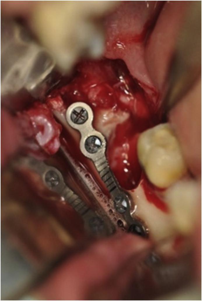
This clinical photograph shows an intraoperative view of an oral and maxillofacial surgical procedure. A 2.0 mm titanium miniplate has been installed along the external oblique line of the mandibular angle. The miniplate features a four-hole bridge design, with monocortical screws secured into the bone. The screws exhibit cross-shaped (Phillips) drive heads. The central bridge section of the plate is narrower than the ends and contains small circular perforations with a ridged surface texture. The surgical field displays exposed yellowish-white cortical bone, hyperemic soft tissue, and some fresh blood at the extraction site of a lower third molar. Adjacent dentition is visible in the background, providing anatomical orientation. This procedure demonstrates the prophylactic use of rigid internal fixation (Champy's technique) to reinforce a weakened mandible and prevent late fractures following the extraction of a deeply impacted third molar in a patient with significant bone thinness.
Rigid Internal Fixation (RIF) for Maxillofacial Fractures
DEFINITION
- Anatomical reduction
- Stable fixation
- Atraumatic technique
- Early active mobilization
HISTORICAL BACKGROUND
| Era | Development |
|---|---|
| 1960s | AO group (Switzerland) - bone compression principles for long bones |
| 1970s | Luhr - introduced vitallium plates for mandible |
| 1975 | Champy et al. - ideal osteosynthesis lines for mandible using miniplates |
| 1980s | Titanium plates introduced; better biocompatibility |
| 1990s-present | Locking plates, resorbable plates, patient-specific implants |
BIOMECHANICAL BASIS
Forces Acting on the Fractured Mandible
BIOMECHANICS OF MANDIBULAR FRACTURE (Drawable Diagram 1)

        Occlusal load (compressive)
              ↓↓↓
    ________________________
   |  UPPER BORDER (TENSION)  |
   |__________________________|
   |  LOWER BORDER (COMPRESSION)|
   |____________________________|

   During function:
   - UPPER border (alveolar side) = TENSION zone
   - LOWER border (inferior) = COMPRESSION zone

   Muscular forces:
   Elevator muscles (masseter, pterygoid, temporalis) pull UPWARD
   Creating TENSION at UPPER BORDER of fracture
Champy's Lines of Ideal Osteosynthesis (1975)
CHAMPY'S LINES (Drawable Diagram 2) - Lateral view of mandible

        .....(tension band - upper border)........
       /                                           \
      /   Symphysis: TWO plates needed             \
     /    (one at alveolar + one at lower border)   \
    /                                                \
   /___________________________________________/
   Lower border (compression zone)

   Body/angle fractures:
   Plate placed along EXTERNAL OBLIQUE LINE
   (along upper border of body/angle region)

   This location neutralizes BOTH tension and torsion forces
TYPES OF IMPLANTS USED IN RIF
A. Based on Material
| Material | Properties | Use |
|---|---|---|
| Titanium | Inert, strong, MRI-compatible, osseointegrates | Most widely used |
| Titanium alloy (Ti-6Al-4V) | Stronger than pure Ti | Load-bearing areas |
| Vitallium (Co-Cr-Mo) | Historical, hard to contour | Now largely replaced |
| Stainless steel | Strong, cheaper, may corrode | Emergency use |
| Resorbable (PLLA, PGA) | Absorbs in 1-2 years, no removal needed | Pediatric, non-load-bearing |
B. Based on Size/Strength
PLATE HIERARCHY (Drawable Diagram 3)

RECONSTRUCTION PLATES (2.4-2.7mm screw)
[====|====|====|====|====]  <- Heavy, thick, load-bearing
     Mandible defects, segmental loss

MINIPLATES (2.0mm screw)
[==|==|==|==]  <- Most common in facial skeleton
   Mandible body, angle, zygoma, midface buttresses

MICROPLATES (1.0-1.5mm screw)
[=|=|=]  <- Thin, delicate areas
   Orbit, nasal bones, frontal sinus

MESH PLATES
[#####]  <- Grid pattern, moldable
   Orbital floor, frontal bone defects
C. Types of Screws
SCREW ANATOMY (Drawable Diagram 4)

Head   Shaft   Tip
 [O]---|=====|--->

Cortical screw: fine thread, for cortical bone
Cancellous screw: coarse thread, for cancellous bone
Self-tapping: cuts its own thread (no pre-tap needed)
Self-drilling: drills and taps simultaneously

MONOCORTICAL: engages only near cortex
  [plate]--[screw head]---> (near cortex only)
  Used: miniplates in tooth-bearing mandible (avoids roots/IAN)

BICORTICAL: engages both cortices
  [plate]--[screw head]-----> (through and through)
  Used: reconstruction plates, symphysis, ramus
D. Locking vs. Non-Locking Plates
| Feature | Non-Locking | Locking (Fixed-angle) |
|---|---|---|
| Screw-plate interface | No lock | Threaded screw head locks into plate |
| Mechanism | Friction | Angular stability |
| Bone contact | Required | Not required (can bridge gaps) |
| Use | Miniplates | Reconstruction, osteoporotic bone |
AO PRINCIPLES OF RIGID FIXATION
1. Absolute Stability (Compression)
INTERFRAGMENTARY COMPRESSION (Drawable Diagram 5)

LAG SCREW PRINCIPLE:
 Fragment A    Fragment B
   [====]       [====]
      \           /
       \         /
        \       /
         [screw]  <- Gliding hole in A, threading in B
                    Pulling B toward A = COMPRESSION

Near cortex: OVERDRILLED (gliding hole = no thread purchase)
Far cortex: UNDERDILLED (thread engages = pulls fragments together)
Net effect: INTERFRAGMENTARY COMPRESSION → primary bone healing
2. Relative Stability (Load Sharing / Load Bearing)
LOAD SHARING vs LOAD BEARING (Drawable Diagram 6)

LOAD SHARING (miniplate):           LOAD BEARING (reconstruction plate):
  [plate across fracture]              [heavy plate spanning defect]
  Bone ALSO carries load               Plate carries ALL load
  Requires bone contact                Bridges segmental defect
  Used: simple fractures               Used: comminuted, defect cases
SPECIFIC APPLICATIONS BY FRACTURE TYPE
1. MANDIBULAR FRACTURES
a. Symphysis / Parasymphysis
SYMPHYSIS FIXATION (Drawable Diagram 7)

   FRONT VIEW OF MANDIBLE (chin)

        Upper plate [= = = = =]   <- At alveolar (tension) border

        [Central incisors]

        Lower plate [= = = = =]   <- At lower border

   TWO plates required:
   - Superior: 2.0mm miniplate at alveolar crest level
   - Inferior: 2.0mm miniplate at inferior border
   (counteracts BOTH tension AND bending/torsion forces)

   OR: Two bicortical lag screws crossing the fracture line
b. Mandibular Body
BODY FRACTURE FIXATION (Drawable Diagram 8)

   LATERAL VIEW:

        Teeth  [=|=|=|=|=|=|=]
                              |
   Upper miniplate [==|==|==] <- Along external oblique line
                              | (above IAN canal - monocortical)
   IAN Canal ------>  ........
                              |
   Lower plate  [===|===|===] <- Along lower border (bicortical)
c. Mandibular Angle
ANGLE FRACTURE (Drawable Diagram 9)

   LATERAL VIEW - Angle region

   External oblique line ------>
                           [===|===]  <- 2.0mm miniplate
                                        Champy's method:
                                        Single monocortical plate
                                        along external oblique line

   Ramus
     |
    [angle]
     |
   Body

   Champy (single superior plate) vs Dual plate technique
   (superior + inferior border) for comminuted fractures
d. Condylar / Subcondylar Fractures
- Conservative/closed: MMF 2-4 weeks for undisplaced fractures
- Open reduction + RIF:
- Indications: displacement >45°, significant shortening, bilateral fractures, foreign body, inability to achieve occlusion
- Approach: retromandibular (Hinds), preauricular, submandibular
- Fixation: two miniplates (trapezoid or delta configuration) or single 3D plate
CONDYLAR FIXATION OPTIONS (Drawable Diagram 10)

   Subcondylar region:

   Option A: Two miniplates (parallel)
   Option B: Single 3D plate (Y or delta shape)
   Option C: Lag screw (for long oblique fractures)

   [ramus]
      |  /
      | /  <- fracture line
      |/
   [condyle]

   Two plates resist:
   - Sagging/distraction (plate 1 = anterior border)
   - Rotation (plate 2 = posterior border)
2. MIDFACE FRACTURES
Le Fort Fractures
Le FORT FRACTURE LINES AND FIXATION POINTS (Drawable Diagram 11)

   Le Fort I:
   [zygomaticomaxillary buttress] - 2.0mm plate × 2 (bilateral)
   [piriform aperture rim]        - 1.5mm plate × 2 (bilateral)

   Le Fort II:
   All Le Fort I points +
   [infraorbital rim]             - 1.5-2.0mm plate
   [nasofrontal region]           - 1.5mm plate

   Le Fort III:
   All Le Fort II points +
   [zygomaticofrontal suture]     - 2.0mm plate (bilateral)
   [zygomatic arch]               - 1.0-1.5mm plate

   KEY BUTTRESSES (vertical support pillars of midface):
   1. Nasomaxillary (ZM) buttress
   2. Zygomaticomaxillary (ZM) buttress ← most important
   3. Pterygomaxillary buttress (posterior, difficult to plate)

   Strategy: Fix the buttresses → restores facial height and projection
Zygomatic Complex (ZMC) Fractures - Tripod Fracture
ZMC FIXATION (Drawable Diagram 12)

   3 FRACTURE SITES OF ZMC:

   1. Zygomaticofrontal suture (ZF)  ← 2.0mm plate
   2. Infraorbital rim               ← 1.5mm plate
   3. Zygomatic arch                 ← 1.0mm plate/no fixation if stable

   [Frontal bone]
       |
    [ZF suture] -- plate 1
       |
   [Zygoma body]
      / \
     /   \
[Arch]  [Infraorbital rim] -- plate 2
           \
        [ZM buttress] -- plate 3 (if needed)

   Minimum 2 points of fixation required for stability
   Gold standard: 3-point fixation (ZF + infraorbital rim + ZM buttress)
3. FRONTAL BONE FRACTURES
- Anterior table: 1.0-1.5mm microplates or mesh after reduction via coronal approach
- Posterior table with dural tear: neurosurgical collaboration; sinus cranialization
4. ORBITAL FRACTURES (Blowout)
- Orbital floor reconstruction with titanium mesh plate
- Mesh contoured to fit orbital floor and medial wall
- Secured with 1.0mm screws at orbital rim
SURGICAL TECHNIQUE - SEQUENCE OF RIF
SURGICAL SEQUENCE (Drawable Diagram 13)

STEP 1: Expose fracture
        (intraoral or extraoral approach)
STEP 2: Reduce fracture
        (restore occlusion if mandible - apply temporary MMF)
STEP 3: Select and contour plate
        (bend plate to exact bone curvature with bending pliers)
STEP 4: Drill first hole (in one fragment)
        (2mm drill bit, 2-3mm from fracture line)
STEP 5: Fix plate to first fragment
STEP 6: Confirm reduction and drill second fragment
STEP 7: Insert all screws (minimum 2 screws per side of fracture)
STEP 8: Release MMF (if mandible) - check occlusion
STEP 9: Wound closure in layers
COMPARISON: MMF vs RIF
| Feature | MMF (Closed) | RIF (Open) |
|---|---|---|
| Jaw mobility | Locked 4-6 weeks | Immediate |
| Nutrition | Liquid diet, weight loss | Near-normal diet |
| Airway | Risk, especially polytrauma | Safe |
| Dental hygiene | Difficult | Normal |
| Non-union risk | Higher (mobile) | Lower (stable) |
| Cost | Low | High |
| Surgical risk | None | Facial nerve, infection, scar |
| Indication | Undisplaced, stable, simple | Displaced, comminuted, condylar, polytrauma |
PLATE AND SCREW SELECTION GUIDE (Rowe & Williams)
| Region | Plate Size | Screw Diameter | Screw Type |
|---|---|---|---|
| Mandible body/angle | 2.0mm | 2.0mm | Monocortical |
| Mandible symphysis | 2.0mm × 2 | 2.0mm | Bicortical |
| Mandible lower border | 2.4mm recon | 2.4mm | Bicortical |
| Condylar region | 2.0mm | 2.0mm | Bicortical |
| Midface buttresses | 1.5-2.0mm | 1.5-2.0mm | Monocortical |
| Orbital rim/wall | 1.0-1.5mm | 1.0-1.5mm | Monocortical |
| Frontal sinus | 1.0mm micro | 1.0mm | Monocortical |
| Zygomatic arch | 1.0-1.5mm | 1.0-1.5mm | Monocortical |
ADVANTAGES OF RIF (over conventional MMF)
- Immediate jaw mobilization - prevents muscle atrophy, trismus
- Improved nutrition - early return to diet
- Better airway management - important in polytrauma, head injury
- Improved patient comfort - no locked jaw
- Better fracture stability - lower non-union and malunion rates
- Allows simultaneous treatment of multiple fractures
- Earlier return to work - social and economic benefit
- Eliminates MMF in edentulous patients where dentoalveolar wiring is difficult
COMPLICATIONS OF RIF
Intraoperative
- Damage to inferior alveolar nerve (IAN)
- Injury to facial nerve branches
- Inadvertent tooth root perforation
- Inadequate reduction
Postoperative - Early
- Infection (0.5-2%)
- Wound dehiscence
- Hematoma
- Malocclusion
Postoperative - Late
- Plate exposure / extrusion
- Plate fracture (reconstruction plates under load)
- Non-union (1-5%)
- Malunion
- Osteomyelitis
- Condylar resorption (after condylar fixation)
- Growth disturbance (in children with rigid titanium plates)
SPECIAL CONSIDERATIONS
Resorbable (Biodegradable) Plates
- Made from poly-L-lactic acid (PLLA) or polyglycolic acid (PGA)
- Resorbed over 1-2 years by hydrolysis
- Advantages: No plate removal surgery, no growth restriction in children
- Disadvantages: Bulkier, weaker, inflammatory reaction (6-18 months), not FDA-approved for load-bearing mandible fixation
- Use: Pediatric non-load-bearing areas (orbital, midface); frontal sinus
3D Plates / Matrix Plates
- Self-supporting grid pattern
- Ideal for condylar region, comminuted fractures
- Distribute stress over wider bone area
Locking Reconstruction Plates
- Used for mandibular defect bridging, segmental loss, tumor reconstruction
- Load-bearing: plate carries all functional forces
- Screws lock into plate at fixed angle → no need for perfect bone contact
KEY EXAMINATION POINTS
- Champy's osteosynthesis lines define where to place miniplates for mandible fractures
- Two plates at symphysis (tension + lower border), one plate at body/angle along external oblique line
- Minimum 2 screws per fragment on each side of the fracture line
- Monocortical screws in tooth-bearing mandible (avoids IAN and roots)
- Bicortical screws at lower border, ramus, condyle, symphysis (edentulous areas)
- Zygoma requires minimum 2-point fixation (ZF suture + infraorbital rim)
- Le Fort fractures are repaired bottom-up (Le Fort I → II → III) restoring occlusion first
- Locking plates provide angular stability without bone-plate contact
- RIF advantages over MMF: immediate mobility, airway safety, better nutrition
- Most significant advance in RIF: Champy's monocortical miniplate technique (1975)
10 mark answer for scc of tongue and surgical management with diagrams from stell and maran
squamous cell carcinoma tongue lateral border clinical appearance
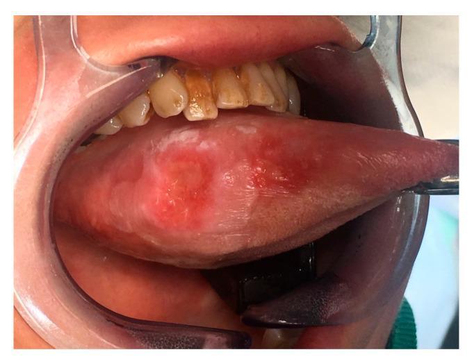
This clinical photograph displays a preoperative view of a large lesion on the right lateral border of the mobile tongue, identified as squamous cell carcinoma (SCC). The lesion is characterized by an exophytic, ulcerated appearance with mixed erythematous (red) and leukoplakic (white) components. Its borders are irregular and poorly defined, showing signs of infiltration into the surrounding lingual mucosa. The oral cavity is accessed using a clear plastic cheek retractor, and a metal surgical instrument is positioned at the tongue tip to facilitate lateral displacement for better visualization. Adjacent anatomical structures include the maxillary teeth, which exhibit extrinsic staining. This image serves as a teaching example of high-stage oral malignancy (T3), demonstrating classic morphological features of lingual SCC such as surface heterogeneity, ulceration, and loss of normal tissue architecture. It is relevant for oncology, oral surgery, and pathology education regarding head and neck cancer presentation.
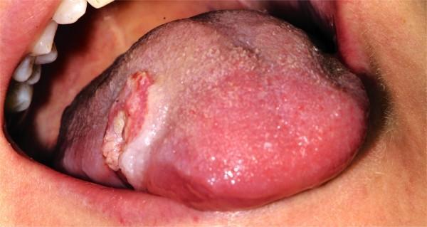
This intraoral clinical photograph shows a frontal view of the oral cavity, highlighting a significant lesion on the middle third of the right lateral border of the tongue. The lesion presents as a 2 cm exophytic, ulcerated mass with irregular, raised, and rolled everted borders—a classic presentation of squamous cell carcinoma. The central ulcerated portion displays a variegated appearance with areas of erythema (redness) and leukoplakia (white patches), suggesting infiltration into the underlying tongue musculature. While the lesion itself appears relatively well-demarcated from the surrounding healthy pink mucosa, it demonstrates aggressive morphology. Adjacent oral structures, including the lower lip and right buccal mucosa, show signs of maceration and leukoedema, likely secondary to a chronic habit such as cheek or lip biting. The visible dentition appears healthy and well-aligned. This image is an essential educational resource for identifying early to mid-stage oral malignancies and distinguishing them from benign oral ulcers based on clinical features like induration, size, and border morphology.
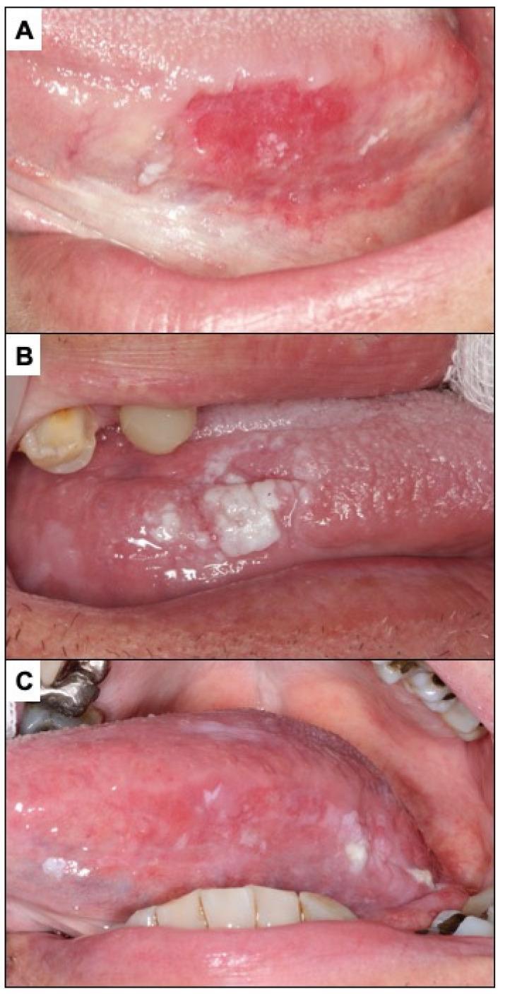
A series of three clinical photographs (A, B, and C) illustrating various clinical presentations of oral potentially malignant disorders and oral squamous cell carcinoma (OSCC) on the lateral border of the tongue. Panel A displays erythroplasia, appearing as a well-demarcated, fiery red, velvety patch on the lateral tongue surface with focal areas of white stippling. Panel B shows a leukoplakia-like presentation of oral carcinoma, characterized by thick, non-homogeneous white plaques (leukoplakia) with an irregular, exophytic surface and granular texture on the lateral border. Panel C demonstrates an advanced oral carcinoma presenting as erythroleukoplakia (speckled leukoplakia). The lesion features a mixed red and white appearance with diffuse erythema, interspersed white patches, and a thickened, granular mucosal texture. The images are representative of oral oncology and oral pathology, highlighting clinical features such as non-homogeneous color distribution, irregular borders, and surface texture changes that are indicative of malignancy or high-grade dysplasia in oral soft tissues.
glossectomy partial total tongue resection reconstruction free flap
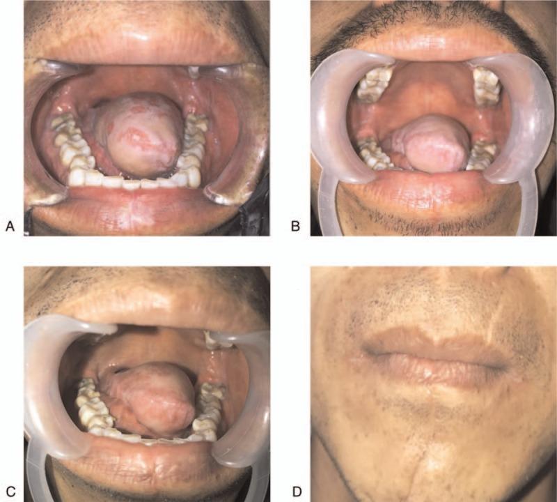
This composite of four clinical photographs documents the postoperative recovery and reconstruction following a partial glossectomy for adenoid cystic carcinoma. Panels A, B, and C provide a longitudinal intraoral view of the tongue reconstruction using an anterolateral thigh (ALT) free flap at 3, 6, and 12 months, respectively. Panel A displays a bulky, smooth-surfaced flap occupying much of the oral floor. By Panel B, the flap shows initial atrophy and increased surface texture. Panel C demonstrates further volume reduction and naturalization of the tongue contour, showing visible folds and a central sulcus-like depression, which facilitates improved speech and swallowing. Panel D is an extraoral facial photograph at 12 months post-surgery, illustrating the healed surgical site. A faint, mature linear scar is visible extending horizontally across the upper lip and philtrum, with subtle changes in skin texture and pigmentation compared to the surrounding perioral tissue. The series demonstrates the success of microvascular free flap reconstruction in restoring oral architecture and achieving functional rehabilitation after major oncological resection in the head and neck region.
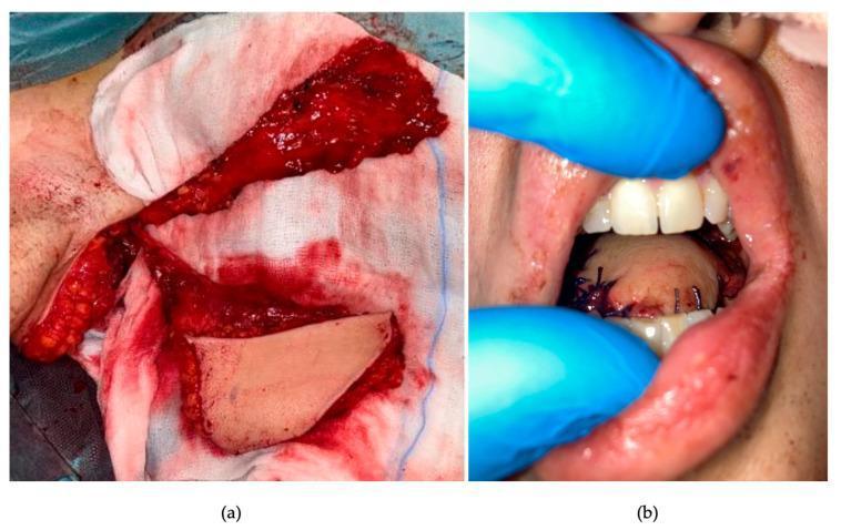
Clinical intraoperative photographs detailing a chimeric free-flap reconstructive procedure for a glossectomy defect. Figure (a) displays a macro view of a latissimus dorsi myo-fascio-cutaneous free flap harvested on a right thoraco-dorsal pedicle. The image shows a highly vascularized, red muscular component (latissimus dorsi) and a distinct, pale, avascular fascial component (serratus anterior) laid out on surgical gauze for inspection prior to transfer. Figure (b) shows the final intraoperative result within the oral cavity. The pale, bulkier myocutaneous component has been used for total tongue reconstruction, while the chimeric fascial component resurfaces the floor of the mouth and tonsillar fossa. The reconstruction is secured with visible black interrupted sutures. Clinical signs of immediate post-operative changes include mild swelling of the flap and minor serosanguinous fluid along the suture lines. This visual material demonstrates advanced microsurgical reconstruction techniques in head and neck oncology, specifically for speech and swallow function restoration following extensive tongue resection.
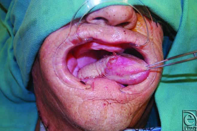
This intraoperative clinical photograph demonstrates a partial glossectomy reconstruction utilizing a free Anterolateral Thigh (ALT) flap. The oral cavity is held open by a transparent plastic retractor, revealing the surgical site. The reconstructed tongue consists of native residual lingual tissue (appearing pink and smooth) and the ALT skin paddle, which is paler with a slightly textured surface. Prominent surgical sutures are visible along the interface where the flap has been inset into the tongue and cheek. Forceps are seen retracting the reconstructed organ to showcase the volume and positioning of the graft. This image illustrates post-oncological head and neck reconstruction, emphasizing the integration of microvascular free tissue transfer to restore oral cavity volume and function. Surgical markings and fresh incisions are also visible on the lower lip and chin areas, typical of a complex oral maxillofacial procedure.
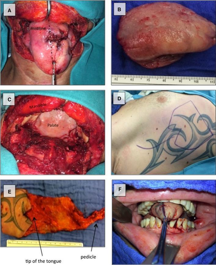
This composite of clinical photographs documents a surgical sequence of total glossectomy and subsequent microvascular reconstruction in a patient with recurrent squamous cell carcinoma. Image A shows the tumor involving the base of the tongue, demarcated by a midline indicator. Image B depicts the gross resected tongue specimen. Image C captures the surgical field post-resection via a transcervical approach, highlighting the exposed mandible and palate within the oral cavity. Images D and E illustrate the donor site and the harvested right-sided myocutaneous serratus anterior free flap (SAFF). The flap includes a skin island, anatomical markers for the neo-tongue tip, and the vascular pedicle. Image F displays the final intraoperative result, showing the reconstructed 'neo-tongue' positioned within the oral cavity and sutured to the remaining oral mucosa. This series serves as an educational resource for head and neck oncology, demonstrating tumor resection margins, flap design for functional reconstruction, and transcervical surgical access.
10 mark answer for scc of tongue and surgical management with diagrams from stell and maran