
Anesthesia in colonoscopy
colonoscopy sedation anesthesia
Anesthesia in Colonoscopy
Overview
- Yamada's Textbook of Gastroenterology, 7e
- Miller's Anesthesia, 10e
Continuum of Sedation Depth (ASA Definitions)
| Level | Responsiveness | Airway | Ventilation | CVS |
|---|---|---|---|---|
| Minimal (anxiolysis) | Normal to verbal | Unaffected | Unaffected | Unaffected |
| Moderate (conscious sedation) | Purposeful to verbal/tactile | No intervention needed | Adequate | Usually maintained |
| Deep sedation | Purposeful only to pain | Intervention may be needed | May be inadequate | Usually maintained |
| General anesthesia | Unarousable | Intervention often needed | Frequently inadequate | May be impaired |
Pre-procedure Assessment
- NPO: 6 hours for a light meal, 8 hours for a full meal, 2 hours for clear liquids (in patients without aspiration risk factors such as GERD, gastric dysmotility, DM, bowel obstruction)
- ASA classification and comorbidities guide drug choice and monitoring level
- Patients with OSA, obesity, extreme anxiety, mental disability, movement disorders, or chronic pain may need deeper sedation or GA even for routine procedures
- Anticoagulation status must be reviewed
Pharmacology of Agents Used
Benzodiazepines
| Drug | Onset | Duration | Dose | Notes |
|---|---|---|---|---|
| Midazolam | 2-5 min | 1-3 h | IV: 0.5-2 mg over 2 min; max ~5 mg | Sedation + amnesia; no analgesia; dose reduce 30% if used with opioids; reduce in elderly |
| Diazepam | 3-10 min | 2-8 h | IV: 2.5-5 mg increments | Less amnesic than midazolam; longer duration |
Opioids
| Drug | Onset | Duration | Dose | Notes |
|---|---|---|---|---|
| Fentanyl | 30 s; peak 5-8 min | 0.5-1 h | IV: 50-100 mcg; redose 25-50 mcg q1-2 min | Short-acting; well suited for outpatient colonoscopy |
| Meperidine | 1-3 min; peak 10-15 min | 2-4 h | IV: 25-50 mg; redose 25 mg q5 min | Slower onset; avoid in renal impairment (normeperidine accumulation) |
Propofol
- Mechanism: Hindered phenolic compound with general anesthetic properties
- Onset: 30-60 seconds
- Duration: 3-10 minutes (rapid recovery)
- Dosing: IV: 20-40 mg slow injection; incremental boluses 10-20 mg every 20 seconds; smaller doses required when combined with opioids or benzodiazepines
- No analgesic effect; weak amnesic effect
- Advantages: Rapid onset, titratable, fast recovery - superior for outpatient colonoscopy throughput
- Disadvantages: Apnea, hypotension, injection-site pain; requires vigilant monitoring
- Administration by non-anesthesiologists (NAPS - nurse-administered propofol sedation) is used in some centers but remains controversial
Safety and efficacy of propofol have been well demonstrated for colonoscopy and EGD. Increasingly, US colonoscopies use propofol, and propofol administration is nearly synonymous with anesthesiologist involvement. - Yamada's Textbook of Gastroenterology, 7e
Remifentanil
- Ultra-short-acting opioid; patients recover earlier than with propofol
- However: more nausea and respiratory depression than propofol groups
- Less commonly used as sole agent
Inhalational Agents (Sevoflurane / Nitrous Oxide)
- When compared with TIVA (propofol + fentanyl + midazolam), inhalational anesthesia patients recovered slower but had less psychomotor impairment at discharge
- TIVA group emerged faster but had longer-lasting psychomotor impairment
Monitoring
- Pulse oximetry (SpO2) - continuous
- Capnography (ETCO2) - recommended; reduces incidence of O2 desaturation and hypoxemia during propofol sedation for colonoscopy (the ColoCap study)
- Blood pressure (NIBP) - intermittent or continuous
- ECG - especially in cardiac patients
- BIS monitoring - useful to titrate depth, particularly when propofol is used
Stimulating Events During Colonoscopy
- Introduction of the endoscope
- Colonic insufflation (with CO2 preferred over air)
- Advancement of scope around flexures
- Biopsy, polypectomy, stenting, dilation, and mucosal resection (endoscopic mucosal resection / ESD) - these require increased analgesia
Reversal Agents
| Agent | Target | Dose | Notes |
|---|---|---|---|
| Flumazenil | Benzodiazepines | 0.2 mg IV; repeat q1 min; max 2 mg | Onset 1-3 min; half-life 53 min (shorter than BZDs - re-sedation may occur); precipitates withdrawal in chronic BZD users; can cause seizures with TCA or carbamazepine |
| Naloxone | Opioids | 0.4-2 mg IV over 30 s; repeat q2-3 min; max 10 mg | Onset 1-2 min; half-life 60-90 min; acute reversal can cause catecholamine surge - tachycardia, hypertension, arrhythmia, pulmonary edema |
Role of the Anesthesiologist vs. Non-Anesthesiologist
| Scenario | Typical Approach |
|---|---|
| Healthy patient, routine colonoscopy | Nurse-administered midazolam + opioid (moderate sedation) |
| High-risk/complex patient | Anesthesiologist-directed MAC with propofol |
| Extremely difficult procedure, poor anatomy, uncooperative patient | Deep sedation or GA |
| Pediatric patients | GA preferred |
Complications
| Complication | Notes |
|---|---|
| Respiratory depression / apnea | Most common serious complication; especially with propofol + opioid combinations |
| Hypotension | Propofol-related; more pronounced with bolus dosing |
| Aspiration | Risk factor for deeper sedation levels |
| Airway obstruction | Risk especially in OSA, obese patients |
| Bowel perforation | Surgical emergency; presents as ongoing abdominal pain post-procedure |
| Bleeding | May occur during therapeutic procedures (polypectomy, ESD); ensure IV access and type & screen |
2025 Evidence Updates
-
Intravenous lidocaine + propofol for colonoscopy (2025, PMID 40102176): Meta-analysis in Anaesthesia examining whether adding IV lidocaine to propofol-based sedation improves outcomes - currently under evaluation.
-
Ciprofol vs. propofol for GI endoscopy (2025, PMID 40033212 & 40636379): Ciprofol (a novel propofol analogue with less injection pain and more stable hemodynamics) shows comparable safety and efficacy to propofol for colonoscopy and EGD in Chinese patient populations - a potential emerging alternative.
Summary
Levels of lymph nodes from Bailey’s nd love
Levels of Lymph Nodes in the Neck
Bailey and Love's Short Practice of Surgery, 28th Edition
Figure 53.3 - Cervical Lymph Node Levels (Bailey & Love 28th Ed.)
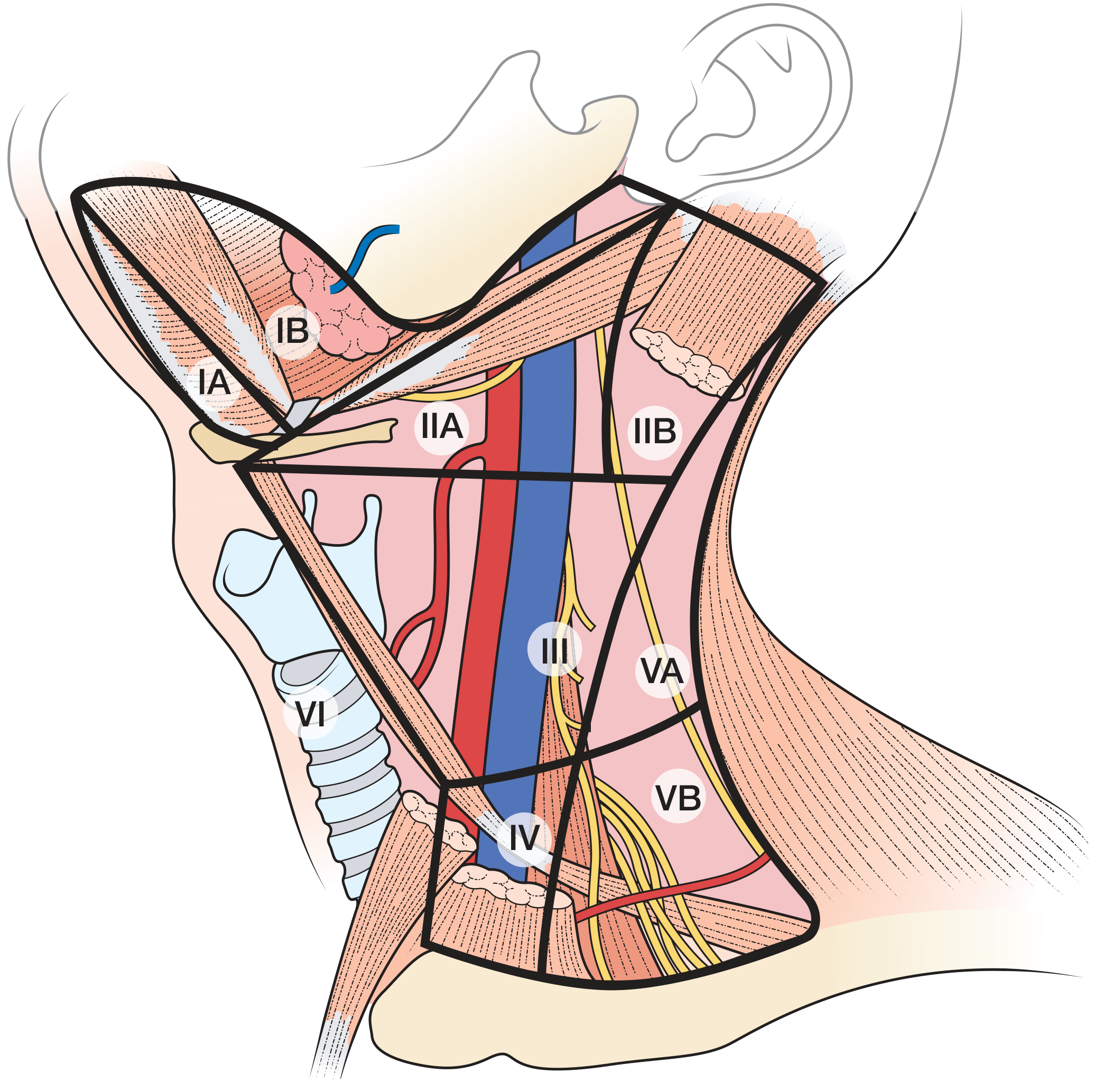
Figure 55.4 - Detailed Anatomical Relationships
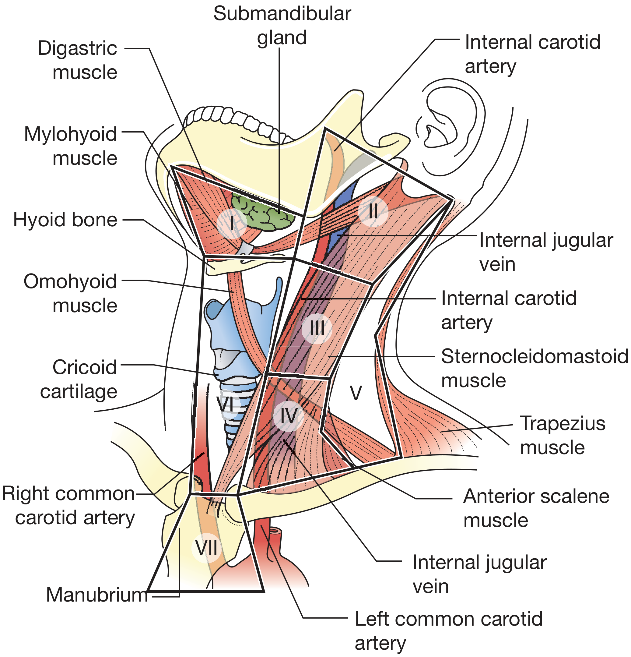
Figure 52.9 - The Level System (All Seven Levels)
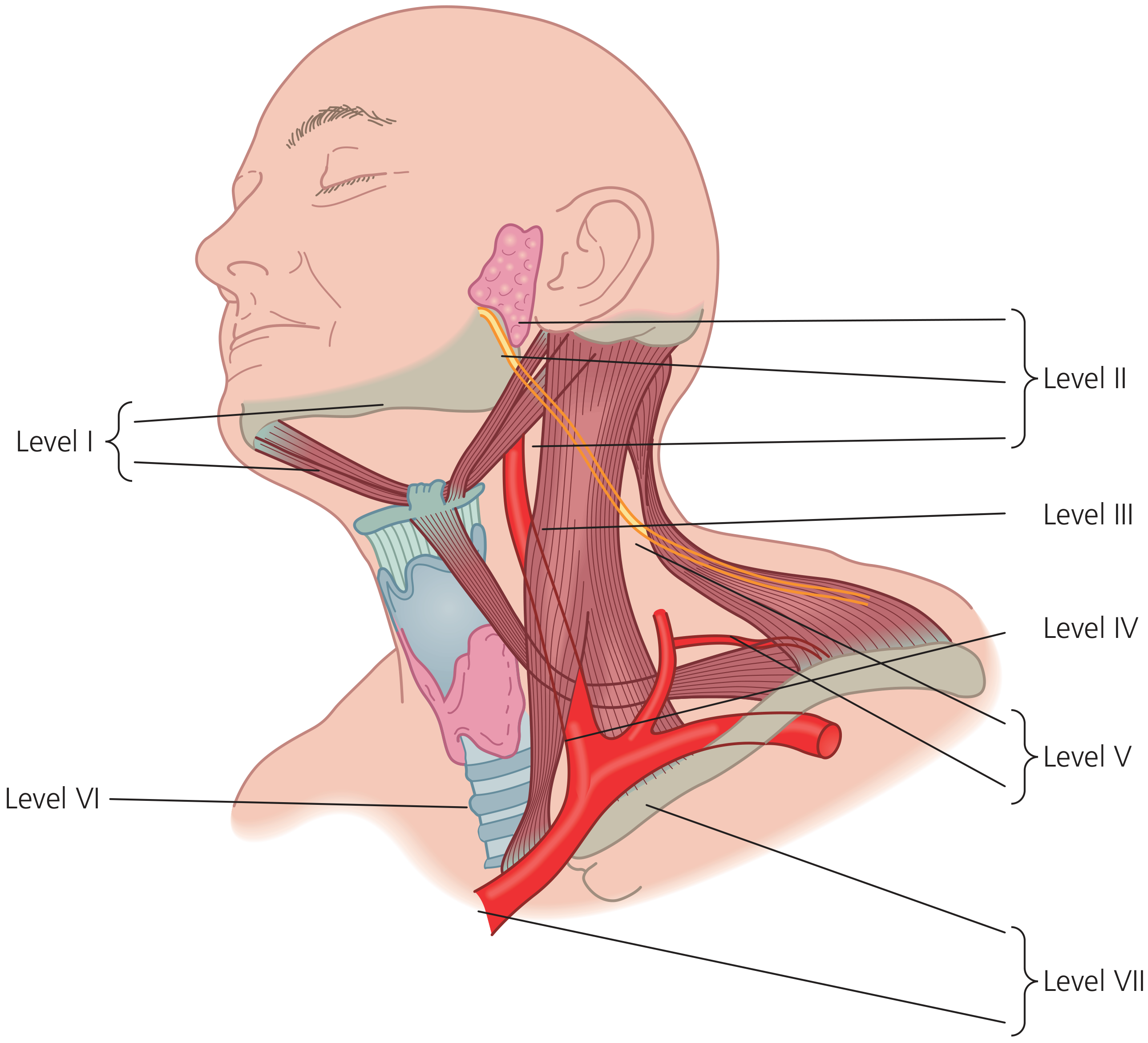
The Seven Levels - Detailed Description
| Level | Name | Location / Anatomical Boundaries | Primary Drainage From |
|---|---|---|---|
| I | Submental & Submandibular group | Above hyoid bone; bounded by the anterior and posterior bellies of digastric and the mandible | Floor of mouth, oral tongue, anterior oral cavity, lip |
| IA | Submental | Between the two anterior bellies of digastric, above hyoid | Chin, lower lip, anterior floor of mouth |
| IB | Submandibular | Bounded by anterior and posterior digastric bellies and the mandible; includes submandibular gland | Oral cavity, anterior nasal cavity, soft tissue of mid-face |
| II | Upper Jugular group | From skull base to inferior border of hyoid; posterior to posterior margin of submandibular gland, anterior to posterior border of SCM | Oral cavity, nasal cavity, nasopharynx, oropharynx, hypopharynx, larynx, parotid |
| IIA | Upper jugular (anterior to CN XI) | Anteromedial to the spinal accessory nerve (CN XI) | As above; most commonly involved in H&N SCC |
| IIB | Upper jugular (posterior to CN XI) | Posterolateral to CN XI; often the "jugulodigastric" node area | Nasopharynx, parotid |
| III | Middle Jugular group | From inferior border of hyoid to inferior border of cricoid; between anterior and posterior borders of SCM | Oral cavity, oropharynx, hypopharynx, larynx |
| IV | Lower Jugular group | From inferior border of cricoid to clavicle; between anterior border of SCM and posterior border of SCM | Hypopharynx, larynx, thyroid, cervical esophagus |
| V | Posterior Triangle group | Posterior to posterior border of SCM; from skull base to clavicle | Nasopharynx, oropharynx, scalp, neck skin |
| VA | Spinal accessory nodes | Upper posterior triangle; along CN XI | Nasopharynx, posterior scalp |
| VB | Transverse cervical / supraclavicular | Lower posterior triangle; along transverse cervical vessels | Thyroid, skin of neck/shoulder |
| VI | Anterior Compartment group | Anterior to common carotid arteries bilaterally; from hyoid to manubrium; between the carotid sheaths | Thyroid, larynx (glottis and subglottis), pyriform apex, cervical esophagus |
| VII | Superior Mediastinal nodes | Below manubrium into superior mediastinum (not all classifications include this) | Thyroid, esophagus, trachea |
Metastatic Patterns by Primary Site
| Primary Site | Most Common Level(s) Involved |
|---|---|
| Oral cavity (SCC) | I, II, III |
| Lips | I, II, III |
| Oropharynx | II, III |
| Nasopharynx | II, III, V (often bilateral) |
| Larynx (glottis) | II, III, IV |
| Thyroid | VI, then III, IV |
| Cervical esophagus | VI, IV |
Types of Neck Dissection (based on Levels)
| Type | Levels Cleared | Structures Preserved |
|---|---|---|
| Classical Radical Neck Dissection (Crile) | I-V | Nothing - IJV, CN XI, SCM all removed |
| Modified Radical Neck Dissection | I-V (all) | One or more of: CN XI, SCM, IJV preserved |
| Selective Neck Dissection | Selected levels only | SCM, CN XI, IJV preserved; exact levels documented |
"Bulky nodal disease may dictate the need for a radical neck dissection, but this operation is less commonly performed owing to a better understanding of the lymphatic drainage of primary sites."
- Bailey and Love's Short Practice of Surgery, 28th Edition
N-Stage (AJCC 8th Edition TNM) - as in Bailey & Love Table 53.2
| N Category | Criteria |
|---|---|
| NX | Regional nodes cannot be assessed |
| N0 | No regional lymph node metastasis |
| N1 | Single ipsilateral node, ≤3 cm, ENE-negative |
| N2a | Single ipsilateral node >3 cm but ≤6 cm, ENE-negative; OR ≤3 cm ENE-positive |
| N2b | Multiple ipsilateral nodes, none >6 cm, ENE-negative |
| N2c | Bilateral or contralateral nodes, none >6 cm, ENE-negative |
| N3a | Any node >6 cm, ENE-negative |
| N3b | Any node, ENE-positive (except single ipsilateral ≤3 cm ENE+, which is N2a) |
Have a detailed research on obtaining kinematic alignment in conventional Total knee arrhroplasty
kinematic alignment total knee arthroplasty conventional
kinematic alignment versus mechanical alignment TKA outcomes
PMID: 40133714
PMID: 40616058
PMID: 36939891
PMID: 37734408
PMID: 41285388
PMID: 40679259
Sources: Campbell's Operative Orthopaedics (15th Ed, 2026), Miller's Review of Orthopaedics (9th Ed), + Current Meta-Analyses
1. Background: Two Alignment Philosophies
| Feature | Mechanical Alignment | Kinematic Alignment |
|---|---|---|
| Philosophy | Correct deformity to neutral axis | Restore native anatomy |
| Mikulicz line | Targeted to pass through knee center | Left unchanged (native) |
| Distal femoral cut | Perpendicular to MAF (mLDFA = 90°) | Made at native mLDFA |
| Proximal tibial cut | Perpendicular to MAT (mPTA = 90°) | Made at native mPTA |
| Ligament balancing | Required (coronal + sagittal planes) | Not required |
| Primary advantage | Symmetrical implant loading | Ligament compatibility; natural feel |
| Primary disadvantage | Balancing in two planes is difficult; may cause instability | Outlier alignment may reduce implant survival |
"Kinematic alignment philosophy is to maintain native limb alignment because knee ligaments and capsule have developed to function in current limb alignment and should not be adjusted."
- Miller's Review of Orthopaedics, 9th Edition
2. Key Anatomical Concepts
Mechanical Axis Femur (MAF) and Tibia (MAT)
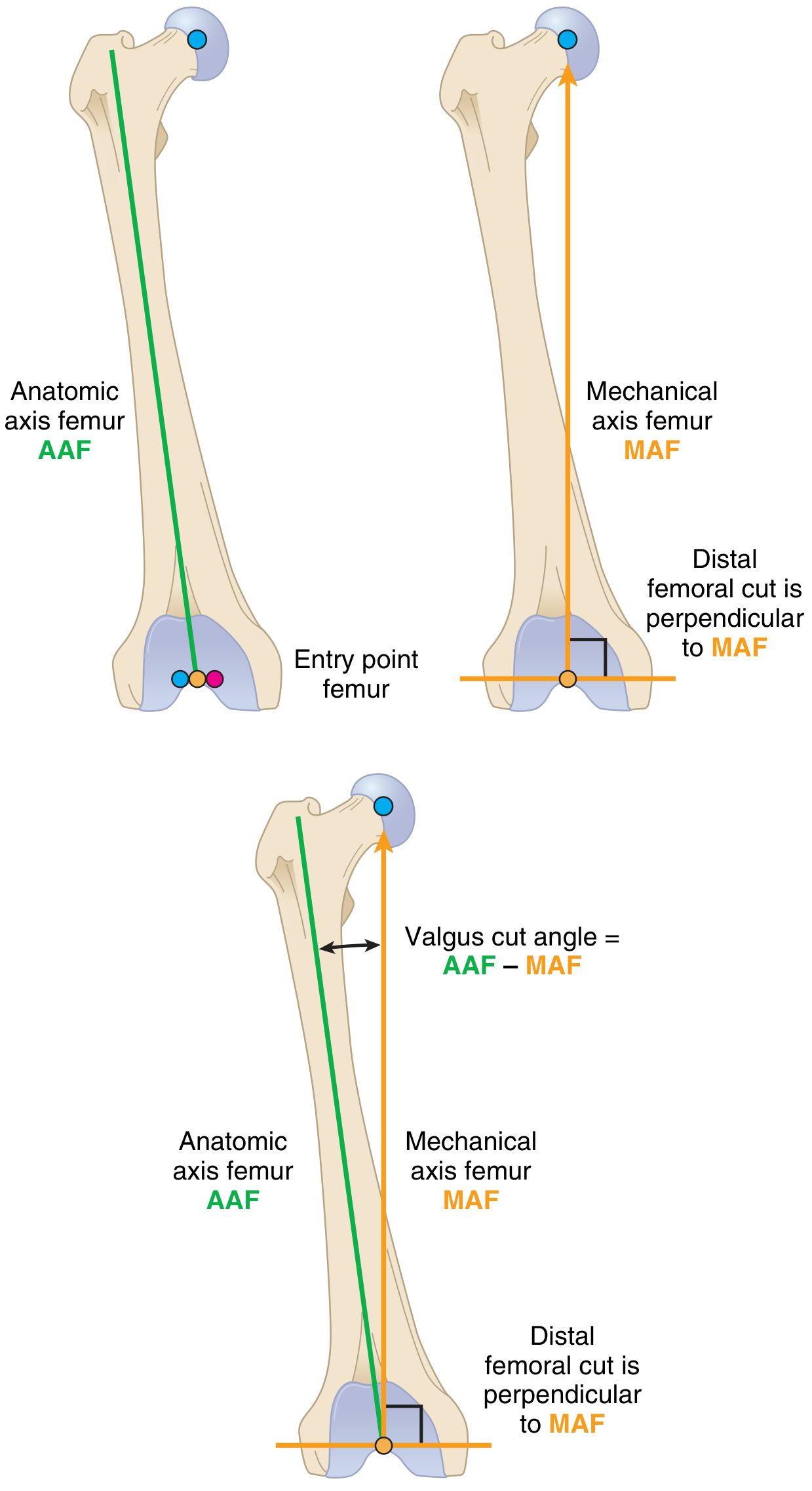
Important Angular Measurements
| Parameter | Definition | Normal Value | MA Target | KA Target |
|---|---|---|---|---|
| mLDFA (mechanical lateral distal femoral angle) | Angle between MAF and distal femoral joint line | ~87° (valgus) | 90° | Native value |
| mPTA (mechanical proximal tibial angle) | Angle between MAT and proximal tibial joint line | ~87° (varus) | 90° | Native value |
| mHKA (mechanical hip-knee-ankle angle) | Coronal limb alignment from hip to ankle | 0° (neutral) | 0° | Preserved as-is |
| JLO (joint line obliquity) | MPTA + LDFA | ~174° | Changed to 180° | Preserved |
| Valgus cut angle (IM rod setting) | Angle between AAF and MAF | 4-7° | 4-7° | Patient-specific |
| Posterior tibial slope | Sagittal tibial inclination | ~7° | ~0-3° | Native slope preserved |
Coronal Plane Alignment of the Knee (CPAK) Classification
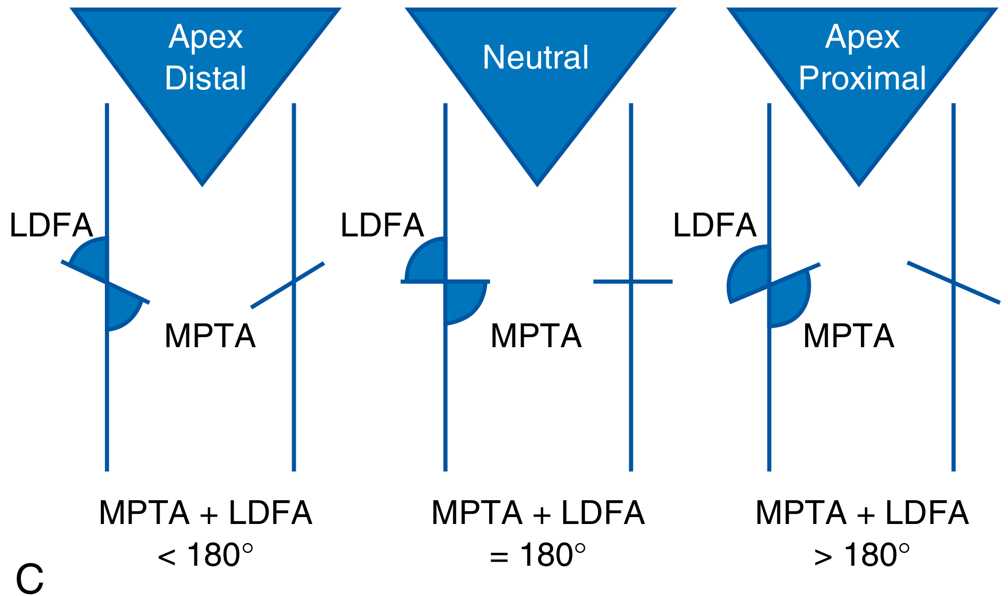
3. Three Variants of Kinematic Alignment
a) Unrestricted KA (True KA)
- Bone cuts set exactly to native LDFA and MPTA without any limit
- Fully restores the patient's native anatomy, including pathological variants
- Risk: extreme outliers (e.g., tibial varus >3-4°) are associated with higher failure rates
b) Restricted KA (rKA / "Bounded" KA)
- Native anatomy is restored within defined safety limits
- Tibial component: kept within 0-3° varus (never >3° beyond neutral)
- Femoral component: kept within 0-3° valgus of neutral
- Most commonly used clinical variant; provides balance between native feel and implant longevity
c) Adjusted MA with Kinematic Principles ("Kinematic Mechanical")
- Primarily MA framework, but with attention to joint line preservation and phenotype
- Not a distinct technique but rather a surgeon preference applied within MA
4. Obtaining KA Using Conventional Instrumentation (Step-by-Step)
Step 1: Preoperative Planning (Critical)
- Measure the native mLDFA (lateral distal femoral angle referenced to mechanical axis)
- Measure the native mPTA (medial proximal tibial angle)
- Calculate the arithmetic HKA = mPTA - mLDFA
- Classify the CPAK phenotype (varus/neutral/valgus + apex distal/proximal)
- Measure the posterior tibial slope on lateral radiograph
- Measure the sagittal femoral flexion (posterior condylar offset)
Two dedicated RCTs (Smolle et al., Arch Orthop Trauma Surg 2023; Sadoghi et al., J Knee Surg 2024) confirmed that conventional instrumentation achieves adequate restoration of native tibial obliquity and tibial slope in KA TKA when measurements are properly planned preoperatively.
Step 2: Distal Femoral Cut - Setting the Valgus Cut Angle for KA
- Calculate the patient-specific valgus cut angle = (native mLDFA - 90°)
- If native mLDFA = 87°, the valgus cut = 3° (less than typical MA 5-7°)
- If native mLDFA = 92°, the valgus cut = 2° of varus cut (an apex proximal phenotype)
- Insert the IM rod into the femoral canal; adjust the IM cutting jig to the calculated valgus angle
- This produces a distal femoral cut that restores native joint line obliquity on the femoral side
"A kinematic alignment with a 3-degree varus joint line at the tibia and an increased distal valgus cut on the femur may improve functional results after TKA." - Campbell's Operative Orthopaedics, 15th Ed (2026)
- Most standard IM femoral cutting jigs allow adjustment from 0-9° valgus
- The surgeon dials in the patient-specific angle rather than a population-average 5-7°
- Use a preoperative full-length HKA radiograph to determine accurate entry point
Step 3: Proximal Tibial Cut - Restoring Native MPTA
- Native mPTA is typically 85-88° (3-5° varus)
- The tibial cutting jig (EM or IM) must be angled to match native obliquity
- For EM jigs: adjust the coronal angle to match native MPTA
- For IM jigs: the rod is angled within the medullary canal
- Native posterior tibial slope (average ~7°) must also be restored
- Sadoghi et al. RCT (2024) found that CI achieved exact tibial slope in 86% of cases vs. 56% with PSI
- The conventional IM tibial guide must be adjusted to avoid over-flexing the tibial cut
- 78% had tibial obliquity restored exactly (0° deviation)
- 21.3% had a 0-1° deviation
- Only 0.7% had 1-2° deviation
- No case exceeded 2° deviation - confirming conventional instrumentation is adequate for KA
Step 4: Femoral Rotation and Flexion
- In MA: femoral component is externally rotated ~3° relative to the posterior condylar axis (PCA) to form a rectangular flexion gap after the perpendicular tibial cut
- In KA: because the tibial cut is not perpendicular to the mechanical axis but follows native MPTA, the required femoral external rotation is different and must be recalculated
- The gap-balancing approach (tensioning) or measured resection are both used
- Posterior condylar axis, transepicondylar axis (TEA), and Whiteside's AP axis are all reference options
- The IM rod must be angled appropriately to avoid hyperflexion of the femoral component
- Sadoghi et al. (2024): both CI and PSI showed no deviation >1° in sagittal femoral alignment
Step 5: Gap Balancing vs. Measured Resection in KA
| Approach | Description | Use in KA |
|---|---|---|
| Measured Resection | Bone cuts based on preoperative anatomy; ligaments balanced after | Preferred for KA - restores joint line from measurements |
| Gap Balancing | Ligaments tensioned first; cuts made to match | Less naturally suited to KA philosophy |
| Inverse KA (iKA) | Uses gap-balancing principles guided by ligament envelopes | Emerging variant; accepts native soft tissue as guide |
Step 6: Ligament Balancing (or Avoiding It)
- Cuts are made to match the joint line that the native ligaments are adapted to
- The medial and lateral compartments are balanced by the anatomy, not by sequential releases
- Minor releases may still be needed for soft tissue contracture
- In severe preoperative deformity (e.g., varus >15°), true KA may not be achievable without extensive releases - this is when restricted KA limits apply
Step 7: Implant Sizing and Patellofemoral Considerations
- Femoral component size: Must restore distal condylar offset; avoid overstuffing or understuffing
- Patellofemoral joint: KA may alter trochlear groove orientation; studies (Blakeney 2019) showed KA better reproduces normal gait but does not always restore native trochlear anatomy
- Tibial sizing: Posterior tibial slope restoration affects PCL tension and flexion ROM
5. How KA is Achieved with Conventional vs. Other Technologies
| Technology | How KA is Applied | Advantages | Limitations |
|---|---|---|---|
| Conventional IM Jigs | Surgeon adjusts valgus cut angle and tibial obliquity based on preop measurements | Widely available; cost-effective; adequate accuracy (RCT evidence) | Requires careful preop planning; some margin of error (~22% have <1° deviation) |
| Patient-Specific Instrumentation (PSI) | CT/MRI-based custom cutting blocks | Pre-planned cuts; potentially lower error rates in coronal plane | Inferior tibial slope restoration vs. CI (Sadoghi 2024); added cost and lead time |
| Computer Navigation | Real-time tracking of cuts; surgeon adjusts to native angles | High accuracy; intraoperative feedback | Operating time; cost; no improvement in outcomes proven |
| Robotic-Assisted (MAKO, ROSA) | Pre-planned KA cuts executed with robotic arm | Highest precision for complex phenotypes | Cost; availability; no proven outcome superiority over conventional KA |
6. Current Evidence: KA vs. MA - Clinical Outcomes
Meta-Analysis Evidence (2022-2026)
| Study | Year | N | Design | Key Finding |
|---|---|---|---|---|
| Boutros et al. J Knee Surg | 2026 | 21 RCTs | MA of RCTs | KA had significantly better flexion (+2.49°), KSS function (+6.39), KSS satisfaction (+3.11), FJS (+3.79), WOMAC (-6.44), VAS pain at rest (-0.39); no difference in complications/revision |
| Gao et al. BMC Musculoskelet Disord | 2025 | 6 RCTs | RKA vs MA | Restricted KA showed significantly better WOMAC and KSS; no difference in OKS, KOOS, FJS, revision rate |
| Migliorini et al. Arch Orthop Trauma Surg | 2025 | 30 studies, 3133 TKAs | MA | No difference in KSS, KSS-F, VAS, WOMAC, OKS, revision rate; marginally better ROM in KA (p<0.0001) |
| Tian et al. J Orthop Surg | 2022 | Meta-analysis | MA | No significant superiority of either technique established |
RCT on Conventional Instrumentation Specifically (2026)
- KA showed significantly better KSS Pain, WOMAC total, and FJS-12 at 2 years
- Patients with varus alignment showed the greatest benefit from KA
- Most differences did not exceed MCID thresholds
- ROM did not differ significantly between groups
Overall consensus: KA is at least equivalent to MA, with modest but statistically significant early functional and patient satisfaction advantages. Long-term survivorship data remain essential.
7. Outlier Risk and the "Safe Zone" Concept
- Tibial varus >3° (mPTA >3° from neutral = <87°): associated with significantly higher short- and mid-term failure rates
- Femoral varus >3°: similarly at risk
- Campbell's 15th Ed: "Opponents of KA point to the fact that if outliers on the tibia reach 4 or more degrees varus, the rate of short-term and midterm failures is much higher."
rKA Safe Zone:
Femur: mLDFA 85-90° (0-5° valgus from neutral)
Tibia: mPTA 87-90° (0-3° varus from neutral)
Coronal limb: mHKA ±3° from neutral
8. Advantages and Disadvantages of KA in Conventional TKA
Advantages
- No (or minimal) ligament releases required in most cases
- Preserves native kinematics - tibiofemoral contact points and rotational arc maintained
- Better gait pattern (closer to native) shown in gait analysis studies
- Potentially higher patient satisfaction and joint awareness (FJS)
- Eliminates "soft tissue balancing" challenge in two planes
Disadvantages
- Requires meticulous preoperative planning and measurement of native angles
- Risk of implant overload if outliers are not controlled (>3-4° tibial varus)
- May not be suitable for severe coronal deformity (>15° varus/valgus)
- Some increased complexity with conventional instrumentation vs. navigation/robotics
- Long-term survivorship data are still limited compared to MA
9. Step-by-Step Summary: Conventional KA Technique
1. PREOPERATIVE
└── Full-length HKA radiograph
└── Measure native mLDFA, mPTA, HKA, tibial slope, femoral flexion
└── Classify CPAK phenotype
└── Plan restricted KA limits (rKA: tibia ≤3° varus, femur ≤3° valgus)
2. FEMORAL SIDE (Distal Cut)
└── Insert femoral IM guide
└── Set valgus cut angle = (native mLDFA - 90°), patient-specific
└── Make distal femoral cut at native LDFA
3. TIBIAL SIDE (Proximal Cut)
└── Set tibial cutting jig obliquity to match native mPTA (usually 2-3° varus)
└── Set posterior tibial slope to match native (usually 5-9°)
└── Make proximal tibial cut at native MPTA and slope
4. FEMORAL ROTATION (AP Cut)
└── Reference: TEA, AP axis, or gap balancing
└── Adjust ER relative to PCA based on the non-perpendicular tibial cut
└── Create symmetric (or intentionally asymmetric) flexion gap per native anatomy
5. TRIAL REDUCTION
└── Assess gap balance in extension and flexion
└── Verify patellofemoral tracking
└── Minor soft tissue adjustment if needed (should be minimal in true KA)
6. FINAL IMPLANTATION
└── Cement components at verified native orientations
└── Check ROM, stability, and patella tracking
Inlay onlay mesh repair and examples along with pictures
inlay onlay mesh hernia repair technique diagram
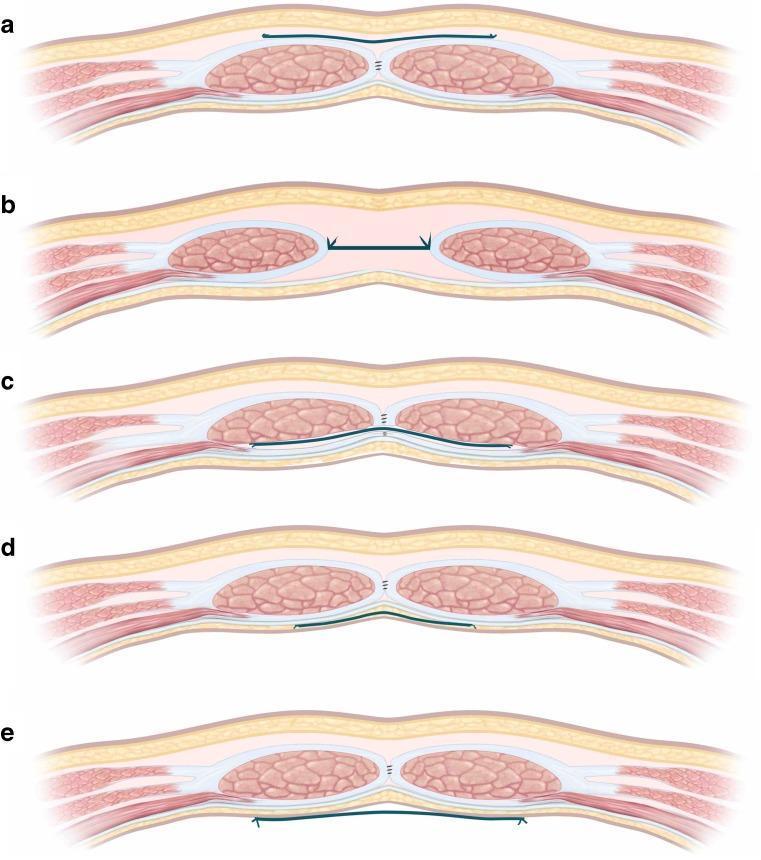
This medical anatomical diagram illustrates five distinct planes for prosthetic mesh placement in ventral hernia repair, shown in axial cross-sections of the anterior abdominal wall. The illustrations categorize mesh positions relative to the rectus abdominis muscle and its sheaths: (a) Onlay: Mesh is positioned superficial to the anterior rectus sheath in the subcutaneous plane. (b) Inlay: Mesh is placed between the edges of the rectus muscles to bridge a fascial defect. (c) Sublay (Retromuscular): Mesh is located posterior to the rectus muscle but anterior to the posterior rectus sheath. (d) Underlay (Preperitoneal): Mesh is positioned deep to the posterior rectus sheath but external to the peritoneum. (e) Intraperitoneal: Mesh is placed within the abdominal cavity, posterior to the parietal peritoneum, often in direct contact with viscera. The diagram serves as a clinical guide for surgical nomenclature and radiological identification of mesh-related outcomes or complications.
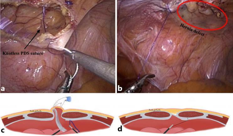
This composite educational material demonstrates the Intraperitoneal Onlay Mesh with Peritoneal Bridging (IPOM-pb) technique for ventral hernia repair, consisting of intraoperative endoscopic photographs (a, b) and corresponding anatomical cross-section diagrams (c, d). In image (a), a laparoscopic grasper manipulates a peritoneal flap. A 'knotless PDS suture' (barbed suture) is used to approximate tissue, reducing dead space within the hernial sac. The diagram (c) illustrates this stage, showing external manual pressure applied to the abdominal wall to facilitate the reduction of the hernial sac while the internal peritoneal flap is pulled down. Image (b) and diagram (d) show the subsequent fixation phase. The hernia defect (highlighted by a red circle in b) is bridged by the peritoneal flap and sutured to the aponeurotic edge. This method provides a flat, vascularized surface for subsequent mesh placement. The visualization emphasizes meticulous tissue handling, the use of monofilament barbed sutures for secure closure without knots, and the strategic reduction of hernia-related dead space to improve clinical outcomes and minimize recurrence.
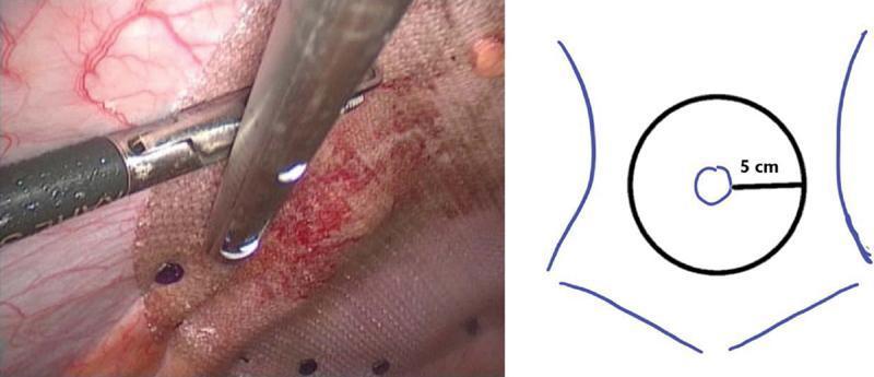
This composite image consists of an intraoperative laparoscopic photograph (left) and a simplified schematic diagram (right) illustrating a laparoscopic ventral hernia repair (LVHR) using the intraperitoneal onlay mesh (IPOM) technique. The surgical photograph shows a woven composite synthetic mesh placed against the internal abdominal wall. Two laparoscopic instruments are visible: an atraumatic grasper holding the mesh taut and a tacker device deploying absorbable fixation tacks (visible as small dark points on the mesh surface). The underlying peritoneum shows normal vascularization and slight surgical hyperemia. The accompanying schematic illustrates the surgical principle of achieving a 5 cm circumferential overlap margin of the mesh around the central hernia defect to ensure mechanical stability and prevent recurrence. This educational material is designed for surgical trainees to understand mesh positioning, mechanical fixation with absorbable tacks, and the geometric requirements for effective hernia repair in a laparoscopic environment.
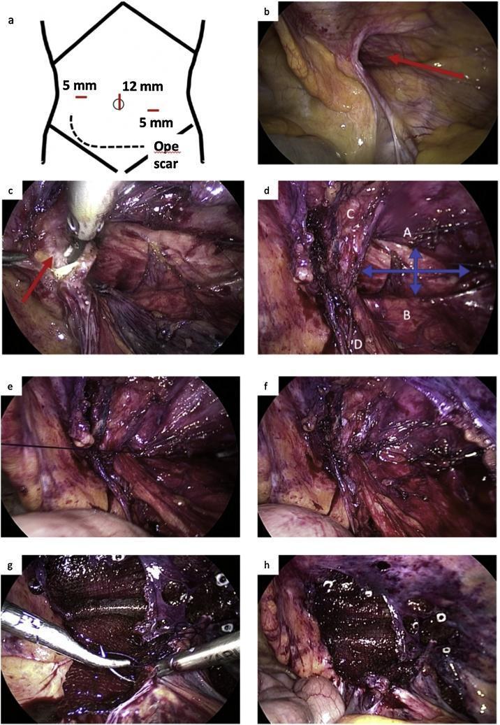
This composite of clinical photographs and diagrams illustrates a laparoscopic indirect inguinal hernia repair using the modified intraperitoneal onlay mesh (mIPOM) technique. Image (a) is a surgical diagram showing trocar placement (5 mm and 12 mm) relative to a previous operative scar. Intraoperative views (b-h) detail the procedural progression: (b) identifies the patent internal hernia ring (red arrow); (c) demonstrates retroperitoneal adhesions near the pubis; (d) shows the completed dissection of the myopectineal orifice with key landmarks: (A) transversalis fascial arch, (B) iliopubic tract, (C) inferior epigastric vessels, and (D) vas deferens, with a blue arrow indicating the widened internal ring. Frames (e) and (f) depict the iliopubic tract repair (IPTR) where the transversalis arch is approximated to the iliopubic tract with interrupted sutures. The final stages (g) and (h) show the placement and fixation of a prosthetic mesh, secured with tackers and a running suture at the inferior-medial corner to cover the sutured internal hernia ring and reinforce the abdominal wall.
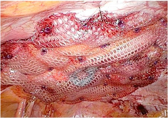
This intraoperative clinical photograph captures a laparoscopic incisional hernia repair using the intraperitoneal onlay mesh (IPOM) technique. The primary focus is a large, white, multifilament polyester mesh with a macroporous, lattice-like structure featuring regularly spaced openings. The mesh is overlaid on the internal abdominal wall to bridge a hernia defect. It is secured to the underlying peritoneal tissue using a 'double-crown' fixation technique with multiple purple-colored absorbable tacks and prefixed threads visible across its surface. The surrounding biological tissue appears pinkish-red and vascularized, with some minor serosanguinous fluid accumulation typical of an active surgical site. A blue marking is visible on a portion of the mesh, likely a manufacturer's orientation guide. This image serves as a clinical example of laparoscopic abdominal wall reconstruction, demonstrating prosthetic placement, mechanical fixation methods, and the interface between synthetic biomaterials and human peritoneal tissue.
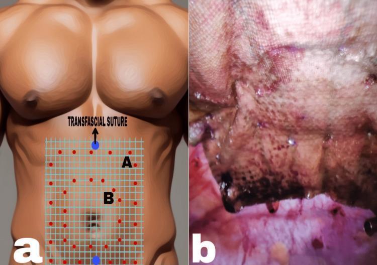
Educational panel illustrating the surgical technique for Intraperitoneal Onlay Mesh (IPOM) Plus hernia repair. Figure (a) is a medical illustration showing a male torso with a superimposed blue grid representing the mesh on the anterior abdominal wall. It demonstrates the 'double crown' fixation technique: red dots indicate tack placement in an outer (A) and inner (B) concentric pattern around the central hernia defect area. Superior and inferior blue dots with black arrows highlight the positioning of 'Transfascial Sutures' for axial mesh anchoring. Figure (b) is a clinical intraoperative photograph showing the actual placement of a composite surgical mesh (polypropylene and oxidized regenerated cellulose). The image reveals the textured, porous surface of the mesh fixed against the abdominal wall tissue. Visible are the fixation points (tacks) and minor focal areas of reddish-purple staining consistent with intraoperative blood and serous fluid. The visual material is intended for surgical education on laparoscopic ventral hernia repair and mesh stabilization methods.
Inlay and Onlay Mesh Repair
Sources: Fischer's Mastery of Surgery (8th Ed), Bailey & Love's (28th Ed), Current Surgical Therapy (14th Ed), Sabiston Textbook of Surgery
Overview: Mesh Placement Positions
Bailey & Love's Fig 64.8 - Layers for Mesh Placement
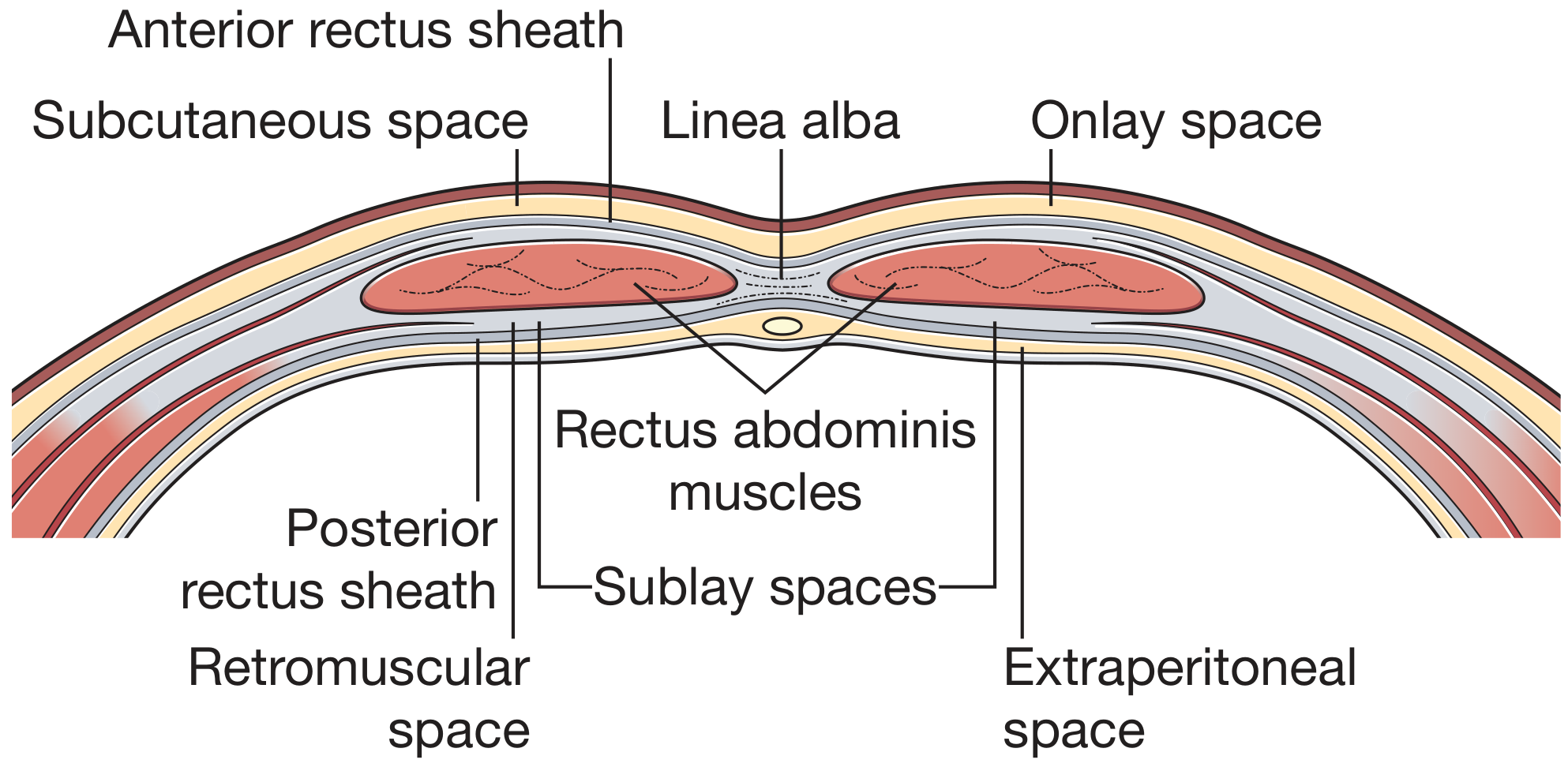
Fischer's Fig 216.5 - ICAP Classification (Onlay, Inlay, Sublay)
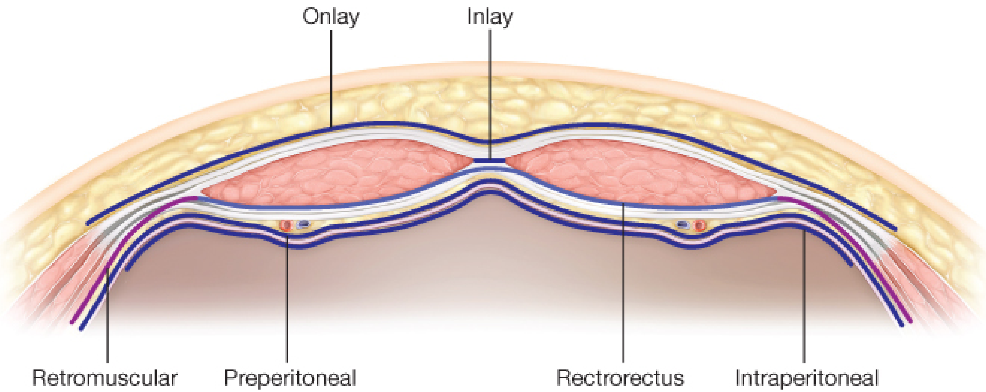
Five-Plane PMC Schematic (a-e)
1. ONLAY MESH REPAIR
Definition
"Mesh placed underneath the subcutaneous tissues on top of the anterior rectus sheath and/or external oblique aponeurosis"
- Fischer's Mastery of Surgery, 8th Ed
Technique (Step-by-Step)
- Incision and exposure: Midline incision; skin and subcutaneous tissue raised as lipocutaneous (skin) flaps off the anterior rectus sheath laterally - only as far as needed for adequate mesh overlap
- Hernia reduction: Hernia contents reduced; hernia sac dealt with
- Primary fascial closure: Anterior rectus sheath edges approximated with slowly absorbable or non-absorbable suture - this is mandatory before placing the onlay mesh
- Mesh placement: Large mesh laid on top of the closed anterior rectus sheath, extending well beyond the defect in all directions (minimum 3-5 cm overlap)
- Mesh fixation:
- Transfascial U-stitches placed circumferentially - 12 o'clock and 6 o'clock first (vertical tension), then 3 and 9 o'clock (horizontal tension)
- Additional interrupted sutures at 1-1.5 cm intervals
- Optional: running suture around mesh edge to prevent irregular contouring
- Fibrin glue (Chevrel technique) or self-gripping mesh (no sutures)
- Dead space management: Progressive tension sutures (lateral-to-medial, through fascia and Scarpa's fascia of skin flap); closed-suction drains placed in subcutaneous space
- Closure: Skin closed in layers
Advantages of Onlay
| Advantage | Explanation |
|---|---|
| Technically easier | No deep myofascial dissection required |
| Larger mesh possible | No anatomical constraint (unlike retrorectus space) |
| No visceral contact | Mesh far from bowel - no barrier coating needed |
| Preserves rectus vascularity | No risk of devascularizing rectus muscle |
| Useful after extensive prior surgery | When posterior sheath is absent or scarred |
Disadvantages of Onlay
| Disadvantage | Explanation |
|---|---|
| Large skin flaps needed | Creates dead space → seroma formation risk |
| Skin necrosis risk | Undermining skin flaps disrupts blood supply |
| Superficial location | Mesh vulnerable to wound contamination/infection if incision breaks down |
| Requires working anterior to forces | Abdominal pressure pushes against, not with, the mesh |
"Onlay meshes may become exposed in the event of wound breakdown, and the elevation of skin flaps to allow wide overlap can lead to skin ischaemia and/or seroma formation."
- Bailey & Love's Short Practice of Surgery, 28th Ed
Clinical Examples of Onlay Repair
- Chevrel repair: Classic onlay with fascial plication and fibrin glue mesh fixation (midline incisional hernia)
- Modified onlay: Mesh placed inferior to released external oblique - a hybrid between onlay and anterior component separation
- Open incisional hernia repair with anterior fascial reinforcement
- Parastomal hernia onlay (less common; higher recurrence)
- Inguinal hernia - Lichtenstein repair: Though inguinal, this is an "onlay" principle - mesh placed on top of the posterior inguinal wall (on the external oblique / inguinal floor) after primary repair
2. INLAY MESH REPAIR
Definition
"If placed between the muscles without any overlap to bridge the defect as an interposition mesh, this is defined as an inlay repair. Notably, this type of repair should be avoided during elective hernia repair."
- Fischer's Mastery of Surgery, 8th Ed
"Inlay meshes are not recommended as they are effectively no more than a suture repair at each mesh-tissue interface."
- Bailey & Love's Short Practice of Surgery, 28th Ed
Why It Is Inferior
- The mesh-tissue junction is under pure tension - the mesh is essentially treated like a suture
- No overlap means no margin for error - any edge failure = hernia recurrence
- Mesh is exposed to the peritoneal cavity (adhesion risk) AND to the subcutaneous space (infection risk)
- No tissue ingrowth from the deep muscular layers that reinforces the repair
When Inlay Is Used (Indications)
- Non-closable defects: When fascial edges cannot be brought together, even after component separation - inlay is preferred over leaving the defect completely open
- Contaminated/emergency fields: When the patient is too unstable for complex reconstruction and a temporary bridge is needed
- Bridge repair in strangulation/bowel resection: Vicryl (absorbable) bridge mesh can be used if omentum is placed between mesh and intestines
- Giant ventral hernias with loss of domain: Initial bridge in staged repair
Technique
- Dissect edges of the fascial defect; open hernia sac; reduce contents
- Close the peritoneum if possible (running absorbable suture) to separate mesh from bowel
- Anchor the mesh to the lateral rectus sheath at the semilunar line (stronger than the defect edge alone) using interrupted permanent sutures
- Alternatively: anchor at the fascial defect edges with interrupted full-thickness bites
- Ensure mesh lies flat without tension or wrinkles
- Mesh type required: Anti-adhesive barrier-coated composite mesh (since mesh faces peritoneal cavity); absorbable mesh (Vicryl) or biologic mesh preferred over permanent uncoated mesh in contaminated cases
Mesh Choice for Inlay
| Situation | Recommended Mesh |
|---|---|
| Clean field | Composite (dual-side) mesh - permanent with adhesive barrier |
| Contaminated / emergency | Slowly resorbable synthetic OR biologic mesh |
| Staged reconstruction bridge | Vicryl absorbable bridge mesh + omentum interposition |
"Inlay mesh repairs are associated with higher recurrence and surgical site events than sublay or onlay meshes."
- Current Surgical Therapy, 14th Ed
3. Comparison: Onlay vs Inlay vs Other Positions
| Feature | Onlay | Inlay | Sublay (Rives-Stoppa) | Intraperitoneal (IPOM) |
|---|---|---|---|---|
| Position | Above anterior rectus sheath | Within defect (bridging) | Behind rectus muscle | Inside peritoneum |
| Fascial closure needed? | Yes (mandatory) | No (that's the problem) | Yes (posterior sheath) | Usually (IPOM+) |
| Overlap | 3-5 cm over fascia | None (just edge fixation) | 5+ cm retromuscular | 5 cm circumferential |
| Mesh coated? | Not required | Yes (anti-adhesive) | Not required | Yes (anti-adhesive) |
| Recurrence rate | Low (similar to sublay) | High | Lowest | Moderate |
| SSI/seroma risk | High (skin flaps) | Moderate | Low | Low |
| Dissection | Moderate (skin flaps) | Minimal | Extensive (retrospace) | Minimal (laparoscopic) |
| Recommended? | Yes (selected cases) | Only if no alternative | Yes - preferred | Yes (laparoscopic) |
4. Named Procedures Using These Principles
Onlay-Principle Procedures
| Procedure | Hernia Type | Details |
|---|---|---|
| Lichtenstein Tension-Free Repair | Inguinal hernia | Polypropylene mesh placed on the posterior inguinal wall (above the inguinal floor), secured to inguinal ligament and conjoint tendon - onlay principle |
| Chevrel Repair | Midline incisional hernia | Fascial plication + onlay mesh + fibrin glue fixation |
| Open Anterior Mesh (McVay/Shouldice variant) | Incisional hernia | Mesh overlaid on anterior rectus sheath after fascial closure |
| Darn repair (historical) | Inguinal hernia | Mesh threads woven through defect edges - essentially an onlay bridge |
Inlay-Principle Procedures
| Procedure | Setting | Details |
|---|---|---|
| Bridge repair | Emergency incarculation/strangulation | Vicryl or biologic mesh bridging unclosable defect |
| Contaminated field bridge | After bowel resection for strangulated hernia | Absorbable mesh + omental interposition |
| Umbilical repair without closure (small) | Thin, fragile fascia | Rare - plug or small disc mesh used as inlay |
Other Mesh Position Procedures (for context)
| Procedure | Position | Description |
|---|---|---|
| Rives-Stoppa repair | Retromuscular sublay | Posterior rectus sheath opened; mesh in retrorectus space; gold standard for incisional hernia |
| TAPP (Transabdominal Preperitoneal) | Preperitoneal | Laparoscopic inguinal hernia; mesh in preperitoneal space |
| TEP (Totally Extraperitoneal) | Preperitoneal | Laparoscopic; purely extraperitoneal access |
| IPOM (Intraperitoneal Onlay Mesh) | Intraperitoneal | Laparoscopic; coated mesh inside peritoneum |
| TAR (Transversus Abdominis Release) | Retromuscular + extended | Releases TAM; creates wider retromuscular space |
5. Why Sublay is Preferred over Onlay and Inlay
- Sublay (retromuscular): Intraabdominal pressure pushes the mesh against the abdominal wall = Pascal's principle - pressure reinforces the repair
- Onlay: Intraabdominal pressure acts against the mesh-fascial suture interface
- Inlay: Intraabdominal pressure acts to separate the mesh from the fascial edges - worst mechanical position
"Meshes placed deep to the abdominal wall muscle layers have a mechanical advantage over onlay positioning as the abdominal pressure helps to keep the mesh in place."
- Bailey & Love's Short Practice of Surgery, 28th Ed
Summary Box
| INLAY | ONLAY | |
|---|---|---|
| Also called | Bridge / Interposition mesh | Anterior mesh |
| Fascial closure | Not performed (mesh IS the closure) | Performed first (mesh reinforces closure) |
| Mesh position | Within the defect (edge to edge) | Above closed anterior rectus sheath |
| Seroma risk | Moderate | High (due to skin flaps) |
| Recurrence risk | High | Low-moderate |
| Bowel contact | Yes (barrier mesh needed) | No |
| When preferred | Only when fascia cannot be closed | Large defects, no posterior sheath, concurrent contaminated intraabdominal surgery |
| Current recommendation | Avoided if possible; last resort | Acceptable but not first choice; sublay preferred |