
Tracheostomy
tracheostomy procedure anatomy tube
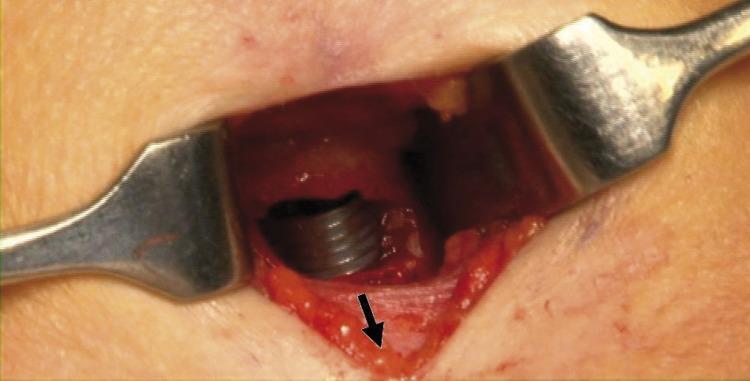
This clinical photograph captures a close-up view of an operative field during a tracheostomy procedure. Metal retractors are positioned to maintain the surgical window through the anterior neck skin and underlying soft tissue. Deep within the incision, a dark-colored, wire-reinforced endotracheal tube (ETT) is visible, showing characteristic spiral threading. The ETT has been advanced caudally (distally) into the airway to protect the pilot cuff from accidental puncture or damage during the creation of the tracheal window. A black arrow points to the exposed cartilaginous tracheal wall, indicating the planned site for the stoma. The image demonstrates key surgical anatomy and airway management safety maneuvers essential for surgical residents and otorhinolaryngology students learning about elective tracheostomy techniques and complication avoidance.
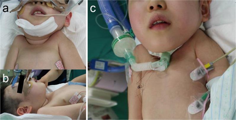
This three-panel clinical series documents a pediatric tracheostomy procedure. Panels 'a' and 'b' show the preoperative state with the patient in a supine position under general anesthesia. An oral endotracheal tube is secured with white tape and padding. Panel 'a' (anterior view) and panel 'b' (lateral view) demonstrate maximum neck extension to provide access to the anterior neck space, despite clinical evidence of limited mobility. ECG electrodes are visible on the upper chest. Panel 'c' shows the postoperative result following the insertion of a 5.5 Fr cuffed tracheostomy tube. The tracheostomy cannula is secured to the neck and connected via a clear adapter to a respiratory circuit including a heat and moisture exchanger (HME) filter and blue corrugated ventilator tubing. The image illustrates procedural management in a patient with difficult airway anatomy, specifically highlighting the transition from oral intubation to a permanent tracheostoma for long-term airway support and mechanical ventilation.
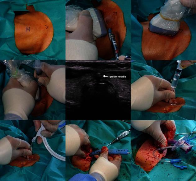
A multi-panel clinical photograph and diagnostic montage illustrating the step-by-step procedure of an ultrasound-guided percutaneous dilatational tracheostomy (PDT). The sequence begins with preoperative skin marking of the cricoid cartilage and sternal notch, followed by local anesthetic infiltration. A central axial ultrasound image depicts the thyroid isthmus (labeled 'I') and a hyperechoic guide needle positioned for tracheal entry. Surgical panels show the transition from needle insertion to guidewire placement via the Seldinger technique. Subsequent frames demonstrate the use of the Ciaglia Blue Rhino kit, showing progressive tracheal dilatation over the guidewire using a curved, tapered dilator. The final panels exhibit the insertion and securing of the tracheostomy tube (T-tube). The image highlights the integration of real-time imaging with surgical maneuvers to enhance safety by visualizing the cervical vasculature, thyroid anatomy, and endotracheal tube positioning during the procedure. This educational material is intended for advanced medical training in critical care, anesthesiology, or otolaryngology.
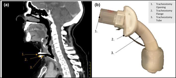
This dual-panel educational figure illustrates tracheostomy tube placement and anatomy. Panel (a) is a sagittal CT scan of the head and neck showing a tracheostomy tube in situ. The image highlights the anatomical relationship between the hardware and surrounding structures, including the anterior neck soft tissues, the tracheal lumen, and the posterior cervical spine. Numerical labels identify the tracheostomy opening (1), flange (2), and tube (3) as they penetrate the skin and enter the airway. Panel (b) provides a physical clinical photograph of the tracheostomy device, identifying the same three components: the proximal connector/opening for respiratory support, the curved stabilizing flange designed to rest against the skin, and the distal curved tube that resides within the trachea. The image serves as a reference for radiology and clinical practice to understand device orientation and its interaction with midline neck anatomy, useful for airway management training and radiation therapy planning where hardware density may affect dose distribution.
Tracheostomy
Definition & Historical Context
Relevant Anatomy
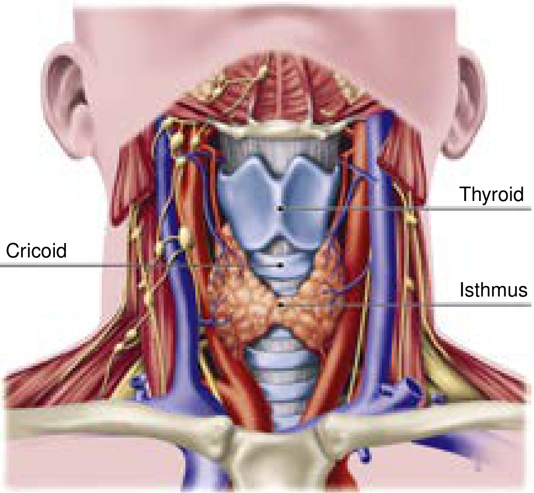
- The trachea extends obliquely from the superficial neck posteriorly into the mediastinum; average length is 11 ± 1 cm in males, 10 ± 1 cm in females
- Tracheal diameter differs by sex: 2.5-2.7 mm in men, 2.1-2.3 mm in women (important for tube sizing)
- Contains 18-22 incomplete semicircular cartilaginous rings
- The cricoid cartilage has the only complete cartilaginous ring and connects to the first tracheal ring inferiorly
- The posterior/membranous trachea is composed of fibroelastic tissue - this is the most vulnerable wall during percutaneous techniques
- The thyroid isthmus typically overlies the 2nd-3rd tracheal rings and may need to be retracted or divided
- The anterior jugular veins and innominate artery (especially if high-riding) are critical vascular structures at risk
- Ideal tracheostomy entry: between rings 1-2 or 2-3; entry at the cricothyroid membrane risks stenosis; entry too inferior risks tracheo-innominate artery fistula
Indications
| Category | Examples |
|---|---|
| Upper airway obstruction | Significant maxillofacial trauma, angioedema, upper airway tumors, difficult airway |
| Neurologic conditions preventing safe extubation | Brain injury (acute or progressive), spinal cord injury (including halo fixation), severe agitation/delirium, prolonged altered mental status |
| Prolonged mechanical ventilation | Expected ventilation >2 weeks, failure to wean |
Contraindications (mostly relative)
- Recent anterior neck surgery (<7 days)
- High ventilator settings: FiO₂ >50%, PEEP >10 cm H₂O, or advanced ventilator modes
- Elevated intracranial pressure
- Hemodynamic instability
- Significant bleeding risk / coagulopathy
- Local infection or malignancy at the proposed site
- Predicted early mortality
Advantages Over Translaryngeal Intubation
- Reduced sedation needs - no glottic stimulation
- Reduced dead space and tube resistance, lowering work of breathing
- Improved mouth care and oral hygiene
- Better bronchial toilet for patients being weaned
- Greater patient comfort, allowing communication/swallowing assessment
Timing
- Early tracheostomy (within 48 hours): One RCT in medical ICU patients showed significant reduction in mortality (32% vs. 62%), pneumonia (5% vs. 25%), and accidental extubation, along with shorter ICU stay and fewer ventilator days
- TracMan Trial (UK, >900 patients): Comparing early (before day 4) vs. late (after day 10), found no mortality difference at 30 days to 2 years; notably, >50% of patients in the late group never needed a tracheostomy because they were successfully liberated from ventilation
- Systematic reviews generally support: shorter ICU stays and fewer ventilator days with early tracheostomy, but no mortality benefit
Techniques
1. Open Surgical Tracheostomy
- Shoulder roll placed, neck extended
- Vertical or horizontal skin incision made between cricoid and sternal notch
- Subplatysmal flaps developed; strap muscles divided in midline
- Thyroid isthmus identified and retracted (or divided with electrocautery and suture ligation)
- Cricoid hook placed to elevate tracheal rings
- Tracheal incision between 2nd and 3rd rings - horizontal or vertical
- ETT retracted just proximal to tracheal lumen
- Tracheostomy tube inserted under direct visualization
- Ventilation confirmed (auscultation, capnography, tidal volume return)
- Neck plate secured with 3-0 Prolene sutures
2. Percutaneous Dilatational Tracheostomy (PDT)
- Pre-procedure review of history, imaging (CT for vascular anatomy), labs (platelets, PT/PTT, BUN)
- Ultrasound assessment of neck vasculature recommended
- Patient positioned with shoulder roll; FiO₂ increased to 1.0
- Sedation, analgesia, and short-acting paralysis administered
- Bronchoscope positioned at distal end of ETT; scope withdrawn and transilluminated through anterior tracheal wall to confirm midline entry
- 1-1.5 cm skin incision, blunt dissection to tracheal rings
- Seldinger technique: needle insertion between rings 1-2 or 2-3, guidewire passage confirmed bronchoscopically
- Serial dilation (Ciaglia Blue Rhino kit - single tapered curved dilator OR serial dilators / Griggs blunt forceps technique)
- Tracheostomy tube advanced over guidewire into trachea
- Position confirmed; ETT removed
- Fewer wound infections
- More cost-effective
- Similar overall complication rate
- Periprocedural mortality <0.2%; major complication rate ~0.15%
Tracheostomy Tube Sizing
| Jackson Size | Inner Diameter (with inner cannula) | Inner Diameter (without inner cannula) | Outer Diameter |
|---|---|---|---|
| 4 | 5.0 mm | 6.7 mm | 9.4 mm |
| 6 | 6.4 mm | 8.1 mm | 10.8 mm |
| 8 | 7.6 mm | 9.1 mm | 12.2 mm |
| 10 | 8.9 mm | 10.7 mm | 13.8 mm |
Complications
Perioperative
- Peristomal bleeding - from anterior jugular veins or thyroid isthmus injury
- Posterior tracheal wall injury - laceration through back wall into esophagus
- Extraluminal placement - false tract creation
- Loss of airway
- Hypoxia/desaturation during the procedure
Long-term
- Tracheal stenosis - especially if entry involves cricothyroid membrane or from cuff over-inflation
- Tracheo-innominate artery fistula - life-threatening; risk increases with inferior tube placement or high-riding innominate artery
- Tracheomalacia
- Tracheo-esophageal fistula
- Persistent stoma after decannulation
- Subglottic stenosis
Risk reduction strategies
- Dedicated multidisciplinary tracheostomy teams reduce time to decannulation, length of stay, and adverse events
- Bronchoscopic guidance during PDT
- Ultrasound pre-assessment for vascular anatomy
- Use of trained airway management personnel
Special Populations
- ECMO patients: Tracheostomy can be safely performed at bedside; complications are higher (mostly bleeding-related), but open and percutaneous techniques show similar complication rates
- Uremic patients: PDT is safe; pre-treat with DDAVP; target PT/PTT <1.5x control and platelets >50,000/mm³
- Obese patients: PDT has been demonstrated safe even in higher obesity classes in series of >3000 procedures; however, surgical tracheostomy may be preferred for very challenging anatomy
- Pediatric: Requires careful neck extension, appropriate tube sizing (cuffed tubes like 5.5 Fr); general anesthesia standard
Decannulation
- Resolved need for mechanical ventilation
- Adequate airway protection and cough
- No significant upper airway obstruction
- Manageable secretion burden
- Satisfactory swallowing function (if applicable)