
Clinical anatomy of head
- Scalp (layers, blood supply, danger area, scalp wounds)
- Skull and cranial fossae (bones, sutures, fontanelles, fractures)
- Meninges and dural venous sinuses (epidural, subdural and subarachnoid bleeds, sinus thrombosis)
- Brain blood supply (circle of Willis, stroke territories)
- Cranial nerves I to XII (course, lesions, clinical tests)
- Face (muscles, facial nerve, trigeminal sensory supply, parotid gland, facial spaces)
- Orbit and eye (bony orbit, extraocular muscles, nerve palsies, orbital fractures)
- Ear (external, middle and inner ear, otitis media, hearing loss)
- Nose and paranasal sinuses (epistaxis, sinusitis)
- Oral cavity, tongue, pharynx and temporomandibular joint (dislocation, mandibular fractures)
- Scalp. It has five layers (SCALP): skin, connective tissue, aponeurosis (galea), loose areolar tissue and pericranium. The loose areolar layer is the "danger area". Infection there can spread to the intracranial venous sinuses through emissary veins. Scalp lacerations bleed heavily because the vessels are held open by the dense connective tissue.
- Skull and meninges. The pterion, where the frontal, parietal, temporal and sphenoid bones meet, is the thinnest part of the lateral skull. It overlies the anterior branch of the middle meningeal artery. A fracture here can cause an epidural haematoma. Subdural haematomas come from torn bridging veins. The cranial base has three fossae that transmit the cranial nerves and vessels.
- Face and cranial nerves. The trigeminal nerve (V) supplies facial sensation through its ophthalmic, maxillary and mandibular divisions. The facial nerve (VII) supplies the muscles of facial expression. A lower motor neuron lesion (Bell's palsy) paralyses the whole half of the face. An upper motor neuron lesion spares the forehead.
- Orbit, ear, nose and mouth. Each has its own clinically important structures. Examples are the oculomotor, trochlear and abducens palsies in the orbit, the middle ear's connection to the mastoid and nasopharynx, and Little's area as the source of most nosebleeds.
Which topic of clinical anatomy of the head should I cover in detail?
- Scalp (layers, blood supply, danger area, scalp wounds)
- Skull and cranial fossae (bones, sutures, fontanelles, fractures)
- Meninges and dural venous sinuses (epidural, subdural and subarachnoid bleeds, sinus thrombosis)
- Brain blood supply (circle of Willis, stroke territories)
- Cranial nerves I to XII (course, lesions, clinical tests)
- Face (muscles, facial nerve, trigeminal sensory supply, parotid gland, facial spaces)
- Orbit and eye (bony orbit, extraocular muscles, nerve palsies, orbital fractures)
- Ear (external, middle and inner ear, otitis media, hearing loss)
- Nose and paranasal sinuses (epistaxis, sinusitis)
- Oral cavity, tongue, pharynx and temporomandibular joint (dislocation, mandibular fractures)
- Scalp. It has five layers (SCALP): skin, connective tissue, aponeurosis (galea), loose areolar tissue and pericranium. The loose areolar layer is the "danger area". Infection there can spread to the intracranial venous sinuses through emissary veins. Scalp lacerations bleed heavily because the vessels are held open by the dense connective tissue.
- Skull and meninges. The pterion, where the frontal, parietal, temporal and sphenoid bones meet, is the thinnest part of the lateral skull. It overlies the anterior branch of the middle meningeal artery. A fracture here can cause an epidural haematoma. Subdural haematomas come from torn bridging veins. The cranial base has three fossae that transmit the cranial nerves and vessels.
- Face and cranial nerves. The trigeminal nerve (V) supplies facial sensation through its ophthalmic, maxillary and mandibular divisions. The facial nerve (VII) supplies the muscles of facial expression. A lower motor neuron lesion (Bell's palsy) paralyses the whole half of the face. An upper motor neuron lesion spares the forehead.
- Orbit, ear, nose and mouth. Each has its own clinically important structures. Examples are the oculomotor, trochlear and abducens palsies in the orbit, the middle ear's connection to the mastoid and nasopharynx, and Little's area as the source of most nosebleeds.
"head"[MeSH Terms] AND "anatomy"[MeSH Terms]
pterion middle meningeal artery lateral skull
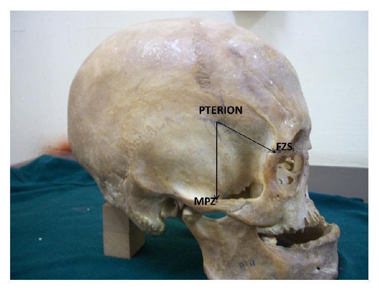
A clinical photograph of a human skull in a lateral (side) view, demonstrating key craniometric landmarks and anatomical relationships used in neurosurgery and forensic anthropology. The image focuses on the pterion, a junction in the temporal fossa where the frontal, parietal, temporal, and sphenoid bones meet. Two black directional lines illustrate surgical or anatomical measurements from the pterion to adjacent landmarks: a vertical line descending inferiorly to the midpoint of the zygomatic arch (MPZ), and an oblique line extending anterior-inferiorly to the frontozygomatic suture (FZS) on the lateral orbital rim. These measurements are clinically significant for localizing deep vascular structures like the middle meningeal artery and identifying the appropriate site for burr hole placement during craniotomy. The skull is positioned on a green cloth, highlighting visible features such as the squamous part of the temporal bone, the external auditory meatus, and the mandible.
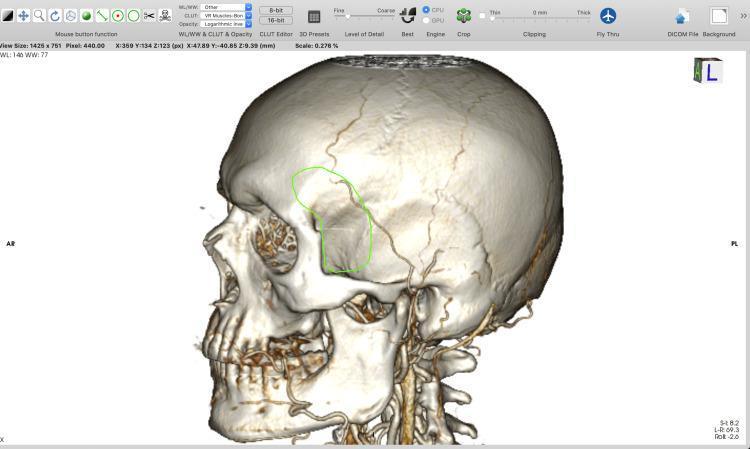
A 3D surface-rendered reconstruction of a human skull, viewed from a left lateral perspective, generated within a DICOM visualization software. The model illustrates high anatomical detail, showing the squamous part of the temporal bone, the greater wing of the sphenoid, the zygomatic arch, and visible cranial sutures such as the coronal and squamosal sutures. Fine branching vascular grooves representing the middle meningeal artery impressions are visible on the temporal-parietal surface. A green outline highlights a specific surgical planning area at the pterion region, intended for a minipterional craniotomy. This region is situated posterior to the frontal process of the zygomatic bone and superior to the zygomatic arch. The software interface displays technical parameters including window level (WL: 146), window width (WW: 77), and scale (0.278%), indicating the model's use in preoperative neurosurgical planning and computer-assisted design (CAD) for potential 3D printing of anatomical models.
1. Scalp
- Bleeding: scalp wounds bleed heavily. Vessels in the dense connective tissue layer are held open and can't retract.
- Danger area: this is the loose connective tissue layer. Infection and blood spread easily through it.
- Emissary veins: they have no valves. They can carry scalp infection into the cranial cavity (Gray's Anatomy for Students, Dural venous sinuses section).
- Galeal laceration: a gaping wound suggests the aponeurosis is cut across. Repair it, because the muscle pull otherwise keeps the wound open.
2. Skull
- Linear vault fractures: the most common.
- Depressed fractures: these can tear the dura.
- Skull base fractures: signs are:
- Raccoon eyes (anterior fossa).
- Battle's sign and haemotympanum (middle fossa).
- CSF rhinorrhoea or otorrhoea.
- Cranial nerve injury.
- Fractures across the sinuses: these may be missed at first. They are a cause of post-traumatic intracranial infection (Gray's Anatomy for Students).
- Anterior: cribriform plate (olfactory nerves).
- Middle: optic canal, superior orbital fissure, foramina rotundum, ovale and spinosum.
- Posterior: internal acoustic meatus, jugular foramen, hypoglossal canal, foramen magnum.
3. Meninges and haemorrhage
| Bleed | Source | Features |
|---|---|---|
| Extradural | Middle meningeal artery | Lens-shaped on CT, may have a lucid interval |
| Subdural | Bridging veins | Crescentic on CT, common in the elderly and alcoholics |
| Subarachnoid | Berry aneurysm rupture | Thunderclap headache |
| Intracerebral | Hypertensive lenticulostriate vessels | Focal deficits |
4. Dural venous sinuses
- Infection from the "danger triangle" of the face spreads through the ophthalmic veins and causes cavernous sinus thrombosis.
- Typical findings are ophthalmoplegia, proptosis and chemosis.
- A carotid-cavernous fistula causes a pulsatile proptosis with a bruit.
5. Brain blood supply
- ACA stroke: contralateral leg weakness more than arm weakness.
- MCA stroke: contralateral face and arm weakness, with aphasia if the dominant hemisphere is involved.
- PCA stroke: contralateral homonymous hemianopia with macular sparing.
- Berry aneurysms: most are at the anterior communicating artery junction. A posterior communicating artery aneurysm causes a painful third nerve palsy.
6. Cranial nerves
| CN | Key clinical point |
|---|---|
| I | Anosmia after cribriform plate fracture |
| II | Visual field defects; afferent limb of the light reflex |
| III | "Down and out" eye, ptosis, dilated pupil |
| IV | Vertical diplopia, head tilt away from the lesion |
| V | Facial sensation; trigeminal neuralgia; motor to the muscles of mastication |
| VI | Medial deviation of the eye; long intracranial course, so it is a false localising sign in raised ICP |
| VII | LMN palsy (Bell's) affects the whole hemiface; UMN palsy spares the forehead |
| VIII | Hearing loss, vertigo; acoustic neuroma at the cerebellopontine angle |
| IX, X | Gag reflex; uvula deviates away from a vagal lesion |
| XI | Weakness of sternocleidomastoid and trapezius |
| XII | Tongue deviates toward the side of the lesion |
7. Face
- Sensory supply: V1, V2 and V3 supply the forehead, midface and lower face respectively.
- Motor supply: the facial nerve leaves the stylomastoid foramen and divides in the parotid gland into temporal, zygomatic, buccal, marginal mandibular and cervical branches ("To Zanzibar By Motor Car"). The parotid contains the nerve, the retromandibular vein and the external carotid artery.
- Parotid surgery: the nerve is at risk. Parotid pain with eating suggests a stone or mumps.
- Arterial supply: the facial artery, with a pulse palpable at the mandible's lower border, and the superficial temporal artery. Giant cell arteritis affects the temporal artery.
- Lymph drainage: it goes to the submental, submandibular and preauricular nodes.
8. Orbit and eye
- Bony floor: it is thin. A blowout fracture can entrap the inferior rectus, causing diplopia on upgaze and infraorbital numbness (V2).
- Extraocular muscles: LR6 SO4 AO3. The lateral rectus is supplied by VI, the superior oblique by IV and the rest by III.
- Orbital cellulitis: it often follows ethmoid sinusitis because the medial wall (lamina papyracea) is thin.
- Superior orbital fissure syndrome: involves III, IV, V1 and VI.
9. Ear
- External ear: the external auditory canal is supplied by V3 and the vagus nerve, which explains reflex cough when the canal is irritated.
- Middle ear:
- The ossicles are malleus, incus and stapes.
- The chorda tympani crosses it.
- It connects to the nasopharynx by the eustachian tube, which is shorter and more horizontal in children, so they get more otitis media.
- It also connects to the mastoid air cells, and infection can spread there or into the cranial cavity.
- The tegmen tympani is the roof, so infection can cause meningitis or temporal lobe abscess.
- Inner ear: the cochlea and the semicircular canals.
10. Nose and paranasal sinuses
- Epistaxis: most nosebleeds come from Little's area (Kiesselbach's plexus) on the anterior septum. Posterior bleeds come from the sphenopalatine artery.
- Sinuses:
- The maxillary sinus drains high on its medial wall, so it drains poorly. Its floor is close to the upper molar roots.
- The frontal and anterior ethmoid sinuses drain into the middle meatus, as does the maxillary sinus.
- The sphenoid sinus lies beside the cavernous sinus and pituitary.
11. Oral cavity, pharynx and TMJ
- Tongue: it has a motor supply from XII. Taste is carried by VII (anterior two thirds) and IX (posterior third). A lingual nerve injury during wisdom tooth extraction causes tongue numbness.
- TMJ: the joint dislocates anteriorly. The mandible is a ring, so a fracture in one place often means a second fracture elsewhere.
- Pharynx: the tonsil sits in the tonsillar fossa. The glossopharyngeal nerve runs close, and the tonsillar artery is a branch of the facial artery.
Recent evidence check
Make a presentation on clinical anatomy of the head
~/
dural venous sinuses cavernous sinus coronal section
layers of the scalp diagram
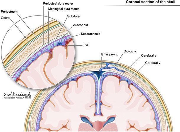
Anatomical diagram of a coronal section of the human skull, detailing the layers from the scalp to the cerebral cortex. The illustration is divided into a main view and a magnified inset for clarity of the superficial layers. Moving from superficial to deep, the labeled scalp layers include the galea aponeurotica and periosteum, which overlie the cancellous bone of the skull. The meningeal layers are clearly delineated: the periosteal dura mater and meningeal dura mater, followed by the subdural space, the arachnoid mater, the subarachnoid space (containing cerebrospinal fluid and vasculature), and the pia mater directly adhering to the brain parenchyma. Key vascular structures are identified, including emissary veins crossing the skull, diploic veins within the bone marrow, and cerebral arteries and veins located within the subarachnoid space and sulci. The diagram also illustrates the falx cerebri extending into the longitudinal fissure and the superior sagittal sinus. This material is designed for neuroanatomy education and clinical correlation with intracranial or extracranial hemorrhages.
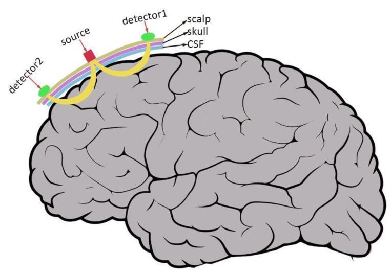
This pathophysiology diagram illustrates the fundamental principles of Functional Near-Infrared Spectroscopy (fNIRS). The visual features a simplified lateral anatomical view of the human brain, showing gray-contoured sulci and gyri. Positioned above the cortical surface is a multi-layered arc representing the scalp (purple), skull (light blue), and cerebrospinal fluid (CSF) (green). On the scalp surface, an optode configuration is shown: a central near-infrared light 'source' (red square) flanked by two 'detectors' (green circles). The diagram highlights the photon path through biological tissue; yellow curved lines originate from the source, penetrate the extracerebral layers (scalp, skull, CSF), enter the brain tissue, and then scatter back to the detectors. This curved trajectory is known as the 'banana-shaped path.' The illustration demonstrates how fNIRS uses light attenuation and scattering to measure hemodynamic responses in the cortex, providing an indirect assessment of neuronal activity. The diagram is an educational resource for clinical imaging and neuroimaging techniques, highlighting the non-invasive nature of light-based brain monitoring.
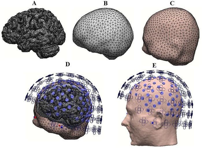
This medical illustration presents a multi-panel anatomical diagram showing the construction of a realistic head model for neuroimaging research, specifically electroencephalography (EEG) and magnetoencephalography (MEG). Panel A displays a high-resolution, wireframe-like three-dimensional rendering of the human brain, emphasizing the intricate gyri and sulci of the cerebral cortex. Panel B illustrates the skull layer, and Panel C depicts the scalp, both rendered using a triangular mesh technique for computational modeling. Panel D provides a composite visualization where the brain, skull, and scalp layers are integrated, featuring transparent sections to show the internal spatial relationships. Superimposed on these layers are blue circular markers and clover-like symbols representing interpolated electrodes and MEG sensors. Panel E shows a sagittal profile of the human head with the systematic grid-like placement of sensors across the scalp surface. This graphic demonstrates the integration of anatomical structures with sensor technology used in source localization and functional brain connectivity studies.
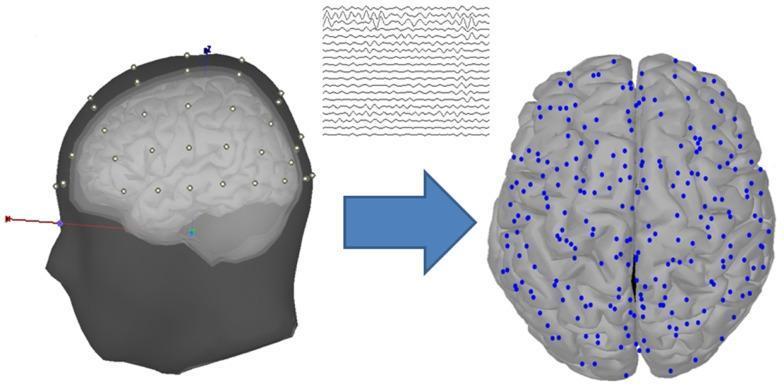
This medical illustration demonstrates the process of EEG source estimation in neuroscience research. On the left, a realistic 3D head model is shown in lateral view, composed of four distinct anatomical layers: the scalp, outer skull, inner skull, and cortex. The scalp surface is marked with white dots representing 60 EEG electrodes arranged according to the International 10-20 system. Above this model, raw multi-channel EEG waveforms are displayed as continuous traces. A blue arrow points toward the right side of the image, representing the mathematical transformation from scalp-recorded signals to source space. The right-hand diagram depicts a superior view of the human brain cortex, with approximately 248 cortical vertices marked by blue dots. These vertices represent current source locations on the cortical surface, localized through source estimation algorithms like sLORETA. The diagram highlights the relationship between surface-level electrode recording and the derived mapping of activity across the cerebral gyri and sulci for functional connectivity analysis.
extradural subdural subarachnoid haemorrhage meninges diagram
circle of Willis arterial anatomy diagram
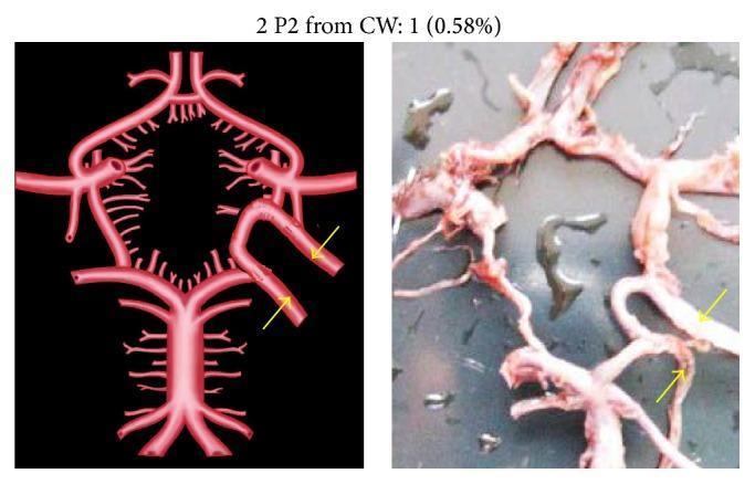
This composite educational resource consists of a side-by-side comparison of a stylized anatomical diagram and a corresponding cadaveric dissection photograph, illustrating a rare morphological variation in the Circle of Willis (CW). The left side features a high-contrast schematic rendering of the cerebral arterial system, while the right side provides a realistic anatomical view of the vascular structures. The focus is on an unusual configuration where two separate P2 segments (postcommunicating segments of the posterior cerebral artery) originate from an accessory or 'extra' vascular loop within the Circle of Willis. Yellow arrows in both the diagram and the photograph specifically highlight these duplicated P2 segments as they branch from the loop. The image serves as a clinical anatomy reference for neurovascular variations, specifically highlighting duplicated P2 segments and anomalous origins from the basilar-internal carotid artery complex. This content is relevant for advanced neuroanatomy, radiology, and neurosurgery training, demonstrating developmental variations that may impact diagnostic interpretation and surgical planning.
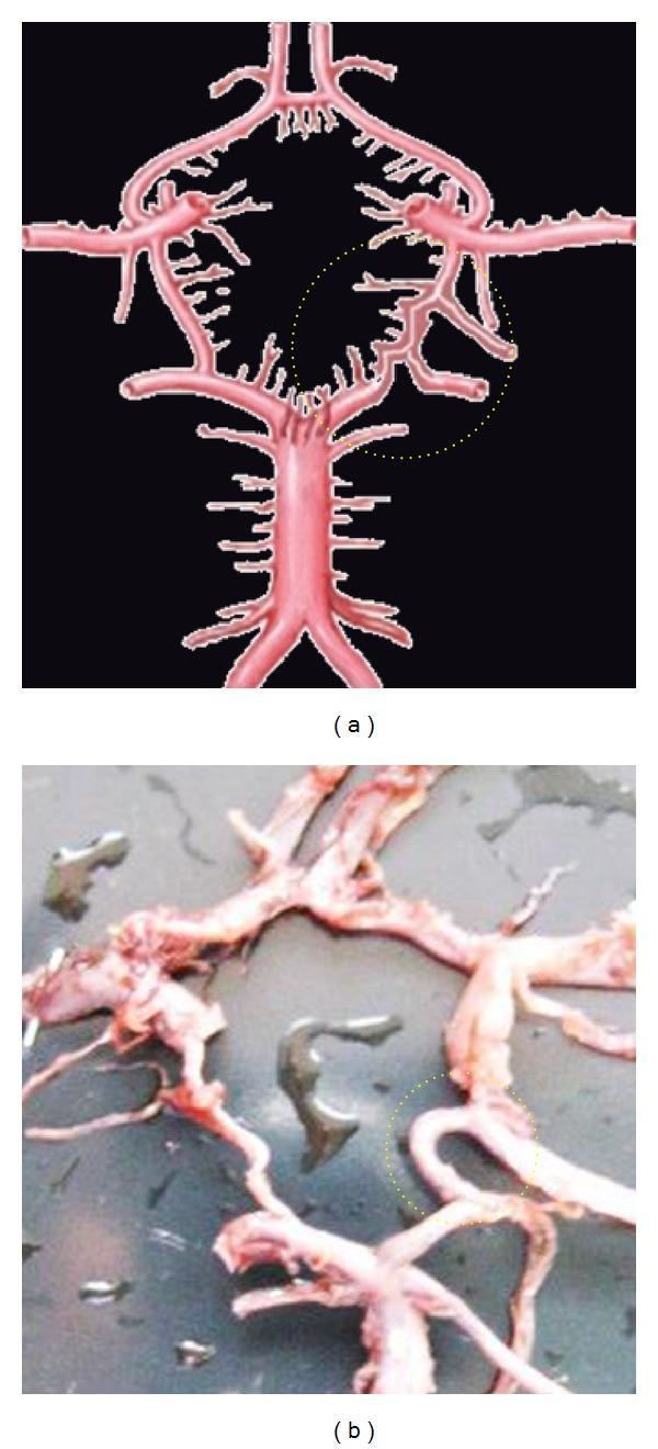
Anatomical comparison of neurovascular anatomy focusing on variations in the Circle of Willis (CW). Panel (a) is a schematic anatomical diagram, and panel (b) is a clinical photograph of a gross anatomical specimen. Both panels highlight a rare arterial variation in the posterior circulation using a dotted yellow circle. In the diagram (a), the variation is depicted as an extra arterial segment located between the posterior cerebral artery (PCA) and the posterior communicating artery (PCoA). This unusual configuration shows the P2 segment of the PCA originating from either end of this extra segment rather than its typical junction. The gross specimen in panel (b) demonstrates the real-world manifestation of this vascular arrangement, showing the converging and branching arterial segments in the basal cistern region. The educational focus of this comparison is to illustrate congenital anatomical variations in cerebral blood supply, which are clinically significant for neurosurgical planning and understanding collateral circulation in cerebrovascular disease.
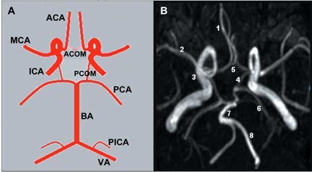
This educational composite image focuses on the anatomy and neuroimaging of the circle of Willis. Panel A is an anatomical diagram providing a schematic representation of a complete arterial circle, illustrating the spatial relationships between the anterior and posterior circulations. Labels identify key vessels including the Anterior Cerebral Artery (ACA), Middle Cerebral Artery (MCA), Internal Carotid Artery (ICA), and the connecting branches like the Anterior Communicating Artery (ACOM) and Posterior Communicating Artery (PCOM). Panel B is a corresponding Maximum Intensity Projection (MIP) from a Magnetic Resonance Angiography (MRA), showing the in vivo vascular architecture. Numerical markers (1-8) correlate the radiological findings with the schematic: 1 (ACA), 2 (MCA), 3 (ICA), 4 (PCOM), 5 (ACOM), 6 (Posterior Cerebral Artery, PCA), 7 (Basilar Artery, BA), and 8 (Vertebral Artery, VA). The image serves as a clinical teaching tool for medical students and radiology residents to understand cerebral vascular patterns, bifurcations, and the collateral flow potential within the intracranial circulation.
facial nerve branches parotid gland anatomy
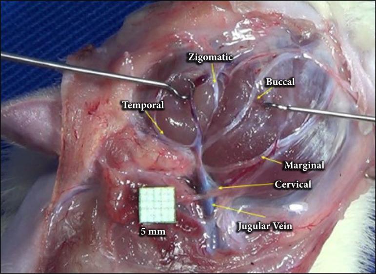
A clinical intraoperative photograph showing the anatomical arrangement of the facial nerve branches in a surgical dissection, following parotidectomy. The image provides a lateral view of the cervicofacial region where the parotid gland has been removed to expose the extratemporal facial nerve plexus. Labeled branches include the temporal branch extending superiorly, the zygomatic and buccal branches traveling toward the mid-face, and the marginal mandibular and cervical branches descending inferiorly. The cervical branch is depicted in close proximity to the jugular vein, which is visible in the lower surgical field. Surgical instruments (retractors) are positioned to maintain exposure of the deep tissues. A 5mm grid scale is included for anatomical measurement. This visual serves as an educational guide for surgical anatomy, identifying key landmarks for nerve preservation during parotid gland surgery or facial nerve decompression.
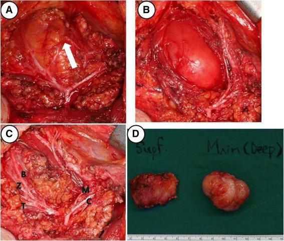
This composite of four clinical photographs illustrates intraoperative findings and gross pathology from a right parotidectomy for a deep-lobe tumor. Panel A shows the surgical field with a white arrow indicating a communicating nerve branch between the marginal mandibular and buccal branches of the facial nerve. Panel B demonstrates the tumor's location within the deep lobe of the parotid gland, adjacent to the masseter muscle. Panel C provides a comprehensive view of the preserved facial nerve branches following dissection, labeled as temporal (T), zygomatic (Z), buccal (B), marginal mandibular (M), and cervical (C). Panel D presents the gross surgical specimens against a green background with a metric scale; it differentiates the irregular superficial lobe parotid tissue ('Supf.') from the main, well-demarcated, multi-lobulated tumor mass ('Main (Deep)'). These images serve as educational material for head and neck surgery, specifically illustrating parotid gland anatomy, facial nerve preservation techniques, and surgical management of parotid neoplasms.
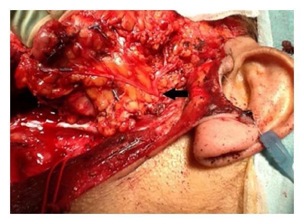
This clinical photograph displays a lateral view of an intraoperative surgical field following a subtotal parotidectomy. The image focuses on the preauricular and cervical regions, where the skin has been reflected to reveal the underlying anatomy. A black arrow indicates the pes anserinus of the facial nerve (Cranial Nerve VII) as it emerges from the parotid gland region. Clearly visible are the thin, yellowish-white, thread-like neural branches radiating from this central point, representing the temporal, zygomatic, buccal, marginal mandibular, and cervical branches. These nerves are preserved and meticulously dissected amidst the surrounding erythematous soft tissue and adipose deposits. The external ear is visible on the right as a landmark, with the neck and jawline extending inferiorly and anteriorly. The image demonstrates surgical anatomy crucial for preventing iatrogenic facial nerve injury during parotid gland surgery, highlighting the spatial relationship between the nerve branches and the deep salivary tissue.
epidural hematoma CT lens-shaped
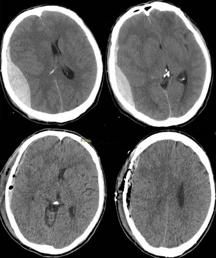
This diagnostic image consists of four non-contrast axial CT scans of the head, providing a pre- and post-operative comparison of an acute epidural hematoma. The top two panels demonstrate a classic biconvex (lens-shaped), hyperdense (bright) extra-axial fluid collection in the right temporoparietal region, characteristic of an acute epidural hematoma. This mass effect is seen compressing the underlying brain parenchyma and causing a significant midline shift toward the left. The bottom two panels show the same patient following surgical evacuation. The hyperdense hematoma has been removed, and the midline shift is markedly improved, reflecting re-expansion of the brain tissue. Surgical changes are visible on the right side of the skull, including a craniotomy site with bone flaps and small pockets of intracranial air (pneumocephalus). This comparison illustrates the typical radiological presentation of an epidural bleed and the immediate anatomical resolution following neurosurgical decompression.
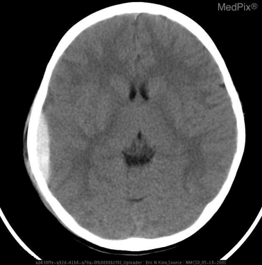
**Imaging Modality:** Non-contrast Computed Tomography (CT) of the head.
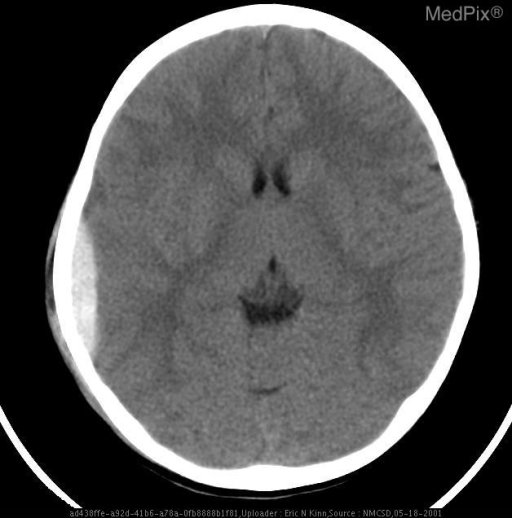
**Imaging Modality:** Non-contrast axial Computed Tomography (CT) of the head.
skull base cranial fossae foramina superior view
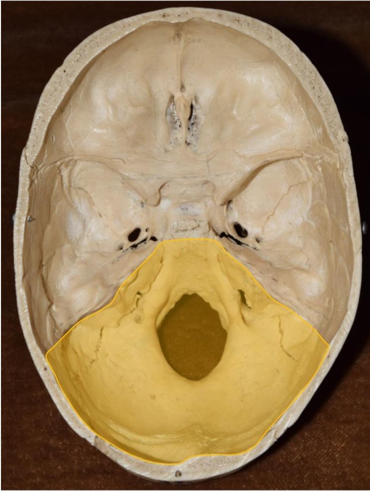
This clinical photograph provides a superior view of the internal cranial floor of a human skull, specifically detailing the three cranial fossae. The posterior cranial fossa is highlighted in yellow, demonstrating its basin-like morphology. This region is primarily composed of the occipital bone and parts of the temporal bones. The most prominent feature is the centrally located foramen magnum, the largest opening for the passage of the spinal cord. Anterior to the foramen magnum, bilateral structures such as the hypoglossal canals and jugular foramina are visible within the posterior fossa boundaries. The unhighlighted regions show the anterior cranial fossa, containing the cribriform plate of the ethmoid bone, and the butterfly-shaped middle cranial fossa, which houses the sella turcica and various foramina (e.g., foramen rotundum, foramen ovale) for cranial nerves and vasculature. The image serves as an anatomical diagram for identifying the boundaries and critical openings of the skull base, essential for understanding neurovascular exits and neurosurgical pathways.
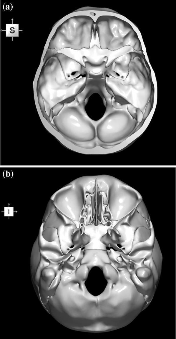
This diagnostic anatomical visualization presents two 3D-reconstructed views of the human skull base, derived from computerized tomography (CT) data. Image (a) depicts the internal surface (superior view), showcasing the cranial fossae (anterior, middle, and posterior). Key visible landmarks include the frontal bone's orbital plates, the centrally located crista galli and cribriform plate of the ethmoid bone, the lesser and greater wings of the sphenoid bone, the petrous part of the temporal bone, and the large posterior foramen magnum. Image (b) shows the external basal surface (inferior view), highlighting the hard palate, the nasal cavity with the vomer and nasal conchae, the pterygoid processes, and the occipital condyles adjacent to the foramen magnum. Both views demonstrate the complex topographical anatomy of the skull base, including critical foramina for neurovascular passage. This material is designed for advanced medical education in neuroanatomy, radiology, and neurosurgery to aid in the study of structural relationships and stereotactic landmarks.
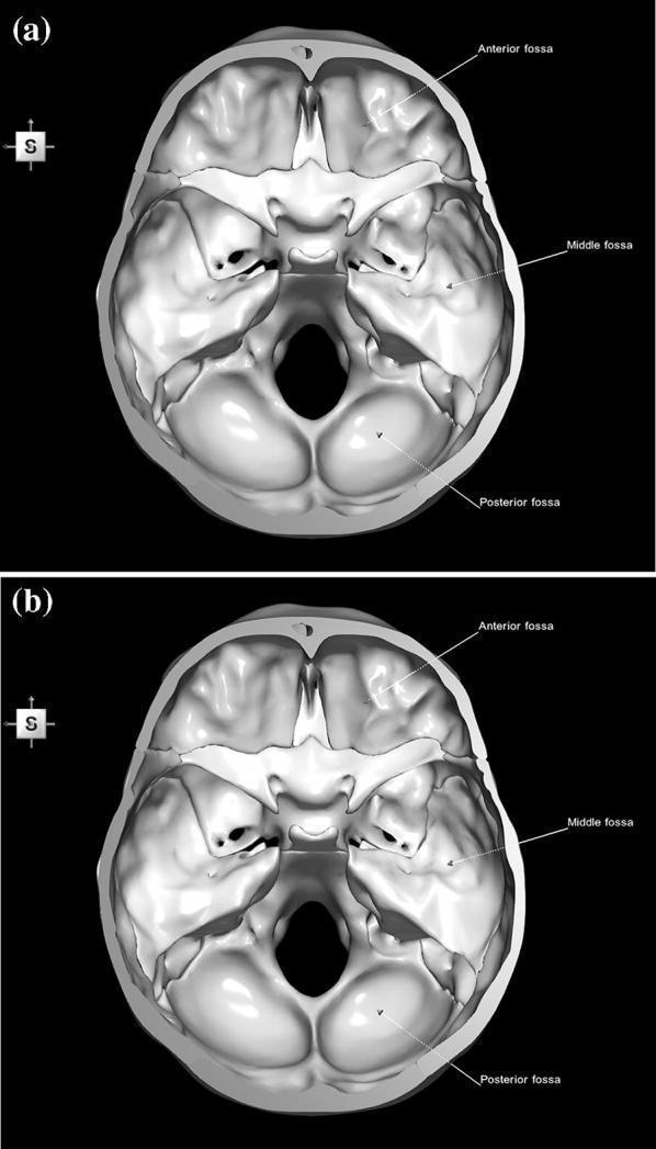
This diagnostic image set consists of two 3D anatomical reconstructions (labeled 'a' and 'b') showing a superior view of the human internal skull base. The images illustrate the topographical divisions of the cranial floor. The Anterior Cranial Fossa is labeled at the front, containing the cribriform plate of the ethmoid bone. The Middle Cranial Fossa is identified by its butterfly-like shape, bounded anteriorly by the lesser wings of the sphenoid and posteriorly by the petrous ridges of the temporal bones. The Posterior Cranial Fossa is the largest and deepest compartment, dominated by the occipital bone and the centrally located foramen magnum. Key landmarks such as the sella turcica, optic canals, and various foramina (ovale, rotundum, spinosum) are visible as structural depressions and openings. Image 'b' represents a color-coded parcellation of the constituent bones—frontal, ethmoid, sphenoid, temporal, and occipital—though presented here in grayscale. This material is designed for neuroanatomical education, specifically focusing on surgical landmarks and the relationship between cranial fossae and brain structures.
mkdir -p /tmp/workspace/head-anatomy-ppt/assets && cd /tmp/workspace/head-anatomy-ppt && python /tmp/skills/shared/scripts/fetch_images.py "https://cdn.orris.care/cdss_images/pmc_clinical_VQA_01627ee7255abd627a2afd2c74d1ce19db27a52fcaa2fde773980eab9357585a.jpg" "https://cdn.orris.care/cdss_images/pmc_clinical_VQA_6838a5e823adae14214f46f0a1d97343ccb35b3d9488ef0bfb44625ae48c27bf.jpg" "https://cdn.orris.care/cdss_images/pmc_clinical_VQA_57108e9479d1dd934d23668718582d57748ae8db4c543a3345efb2b8149fbe82.jpg" "https://cdn.orris.care/cdss_images/pmc_clinical_VQA_1d838f2bf580f34232b27224ed50f01c4a01baa3ada044b5f5db45235a417029.jpg" "https://cdn.orris.care/cdss_images/pmc_clinical_VQA_007bc2c9da326d7d2f216763378a3ebe1e98f913afaa916e56d42367c4962e5e.jpg" "https://cdn.orris.care/cdss_images/pmc_clinical_VQA_335b8e2d809bdbaca452600c9251cfe7a23fdaab5ef968e58dd329757ce3b035.jpg" "https://cdn.orris.care/cdss_images/9f5062720423ba83eff802cdb821515a4b372d0f8ecf241cada5fa233c83266b.png" > assets/imgs.json; python - <<'E' import json,base64 d=json.load(open('assets/imgs.json')) names=['scalp','pterion','fossae','willis','facial','epidural','sinuses'] from PIL import Image from io import BytesIO for n,i in zip(names,d): if i['base64']: raw=base64.b64decode(i['base64'].split(',',1)[1] if ',' in i['base64'] else i['base64'].split(';base64,')[-1]) im=Image.open(BytesIO(raw)); print(n,im.size) im.convert('RGB').save(f'assets/{n}.jpg',quality=90) else: print(n,i['error']) E
cd /tmp/workspace/head-anatomy-ppt && cat > build.py <<'E' from pptx import Presentation from pptx.util import Inches, Pt from pptx.dml.color import RGBColor from pptx.enum.text import PP_ALIGN, MSO_ANCHOR from pptx.enum.shapes import MSO_SHAPE from PIL import Image NAVY=RGBColor(0x14,0x2F,0x4E); TEAL=RGBColor(0x1F,0x8A,0x8A); LIGHT=RGBColor(0xF2,0xF6,0xF8) INK=RGBColor(0x26,0x32,0x38); GREY=RGBColor(0x6B,0x7A,0x84); RED=RGBColor(0xB0,0x3A,0x2E); WHITE=RGBColor(255,255,255) prs=Presentation(); prs.slide_width=Inches(13.333); prs.slide_height=Inches(7.5) BL=prs.slide_layouts[6] FONT="Calibri" def rect(s,x,y,w,h,fill,line=None): r=s.shapes.add_shape(MSO_SHAPE.RECTANGLE,Inches(x),Inches(y),Inches(w),Inches(h)) r.fill.solid(); r.fill.fore_color.rgb=fill if line is None: r.line.fill.background() else: r.line.color.rgb=line r.shadow.inherit=False return r def text(s,x,y,w,h,t,size=16,bold=False,color=INK,align=PP_ALIGN.LEFT,anchor=MSO_ANCHOR.TOP): tb=s.shapes.add_textbox(Inches(x),Inches(y),Inches(w),Inches(h)); tf=tb.text_frame; tf.word_wrap=True tf.vertical_anchor=anchor tf.margin_left=tf.margin_right=Inches(0.05); tf.margin_top=tf.margin_bottom=Inches(0.03) p=tf.paragraphs[0]; p.alignment=align r=p.add_run(); r.text=t; r.font.size=Pt(size); r.font.bold=bold; r.font.color.rgb=color; r.font.name=FONT return tb def bullets(s,x,y,w,h,items,size=16,gap=6): tb=s.shapes.add_textbox(Inches(x),Inches(y),Inches(w),Inches(h)); tf=tb.text_frame; tf.word_wrap=True tf.margin_left=tf.margin_right=Inches(0.05) first=True for it in items: p=tf.paragraphs[0] if first else tf.add_paragraph(); first=False p.space_after=Pt(gap) if isinstance(it,tuple): head,body=it else: head,body=None,it r0=p.add_run(); r0.text="\u2022 "; r0.font.size=Pt(size); r0.font.color.rgb=TEAL; r0.font.bold=True; r0.font.name=FONT if head: r=p.add_run(); r.text=head+" "; r.font.bold=True; r.font.size=Pt(size); r.font.color.rgb=NAVY; r.font.name=FONT r=p.add_run(); r.text=body; r.font.size=Pt(size); r.font.color.rgb=INK; r.font.name=FONT return tb def image(s,path,x,y,w,h,caption=None): im=Image.open(path); iw,ih=im.size; ar=iw/ih if w/h>ar: nh=h; nw=h*ar else: nw=w; nh=w/ar ox=x+(w-nw)/2; oy=y+(h-nh)/2 s.shapes.add_picture(path,Inches(ox),Inches(oy),Inches(nw),Inches(nh)) if caption: text(s,x,y+h+0.02,w,0.3,caption,11,color=GREY,align=PP_ALIGN.CENTER) n=[0] def slide(title,sub=None): s=prs.slides.add_slide(BL); n[0]+=1 rect(s,0,0,13.333,7.5,WHITE) rect(s,0,0,13.333,1.1,NAVY); rect(s,0,1.1,13.333,0.06,TEAL) text(s,0.6,0.15,10.8,0.8,title,30,True,WHITE,anchor=MSO_ANCHOR.MIDDLE) if sub: text(s,9.0,0.15,3.8,0.8,sub,13,False,RGBColor(0xBF,0xD8,0xE0),PP_ALIGN.RIGHT,MSO_ANCHOR.MIDDLE) text(s,0.6,7.05,9,0.3,"Clinical Anatomy of the Head",10,color=GREY) text(s,12.0,7.05,0.8,0.3,str(n[0]+1),10,color=GREY,align=PP_ALIGN.RIGHT) return s def callout(s,x,y,w,h,title,body,color=RED,size=14): rect(s,x,y,0.08,h,color); rect(s,x+0.08,y,w-0.08,h,LIGHT) text(s,x+0.2,y+0.05,w-0.3,0.35,title,size,True,color) text(s,x+0.2,y+0.42,w-0.3,h-0.45,body,size-1,color=INK) def table(s,x,y,w,colw,rows,size=13,rowh=0.42): nr=len(rows); nc=len(rows[0]) gt=s.shapes.add_table(nr,nc,Inches(x),Inches(y),Inches(w),Inches(rowh*nr)); t=gt.table for i,cw in enumerate(colw): t.columns[i].width=Inches(cw) for r in range(nr): t.rows[r].height=Inches(rowh) for c in range(nc): cell=t.cell(r,c); cell.text=""; cell.margin_left=cell.margin_right=Inches(0.08) cell.margin_top=cell.margin_bottom=Inches(0.03); cell.vertical_anchor=MSO_ANCHOR.MIDDLE p=cell.text_frame.paragraphs[0]; run=p.add_run(); run.text=rows[r][c] run.font.size=Pt(size); run.font.name=FONT cell.fill.solid() if r==0: cell.fill.fore_color.rgb=NAVY; run.font.color.rgb=WHITE; run.font.bold=True else: cell.fill.fore_color.rgb=LIGHT if r%2 else WHITE; run.font.color.rgb=INK if c==0: run.font.bold=True; run.font.color.rgb=NAVY return t # 1 Title s=prs.slides.add_slide(BL) rect(s,0,0,13.333,7.5,NAVY); rect(s,0.8,3.55,2.2,0.07,TEAL) text(s,0.8,1.6,11.5,1.9,"Clinical Anatomy of the Head",50,True,WHITE,anchor=MSO_ANCHOR.BOTTOM) text(s,0.8,3.8,11,0.6,"From scalp to skull base: structures that matter at the bedside",22,color=RGBColor(0xBF,0xD8,0xE0)) text(s,0.8,6.5,11,0.4,"Sources: Gray's Anatomy for Students; standard anatomy and clinical texts",13,color=RGBColor(0x8F,0xB0,0xBC)) # 2 Overview s=slide("Overview") items=[("1","Scalp"),("2","Skull and pterion"),("3","Cranial fossae"),("4","Meninges and haemorrhage"),("5","Dural venous sinuses"), ("6","Brain blood supply"),("7","Cranial nerves"),("8","Face and parotid"),("9","Orbit and eye"),("10","Ear"),("11","Nose and paranasal sinuses"),("12","Oral cavity, pharynx and TMJ")] for i,(num,t) in enumerate(items): col=i//6; row=i%6 x=0.8+col*6.1; y=1.6+row*0.88 c=s.shapes.add_shape(MSO_SHAPE.OVAL,Inches(x),Inches(y),Inches(0.6),Inches(0.6)); c.fill.solid(); c.fill.fore_color.rgb=TEAL; c.line.fill.background() tf=c.text_frame; tf.paragraphs[0].alignment=PP_ALIGN.CENTER; r=tf.paragraphs[0].add_run(); r.text=num; r.font.size=Pt(16); r.font.bold=True; r.font.color.rgb=WHITE; r.font.name=FONT tf.vertical_anchor=MSO_ANCHOR.MIDDLE text(s,x+0.8,y,5,0.6,t,22,color=NAVY,anchor=MSO_ANCHOR.MIDDLE) # 3 Scalp s=slide("Scalp","Layers and clinical points") text(s,0.6,1.4,6.2,0.4,"SCALP: five layers, from superficial to deep",18,True,TEAL) rows=[["Letter","Layer","Key point"],["S","Skin","Hair bearing, many follicles"],["C","Connective tissue (dense)","Vessels held open: profuse bleeding"],["A","Aponeurosis (galea)","Links frontalis and occipitalis"],["L","Loose connective tissue","\"Danger area\": infection spreads"],["P","Pericranium","Periosteum of skull bones"]] table(s,0.6,1.9,6.4,[0.8,2.4,3.2],rows,13,0.5) bullets(s,0.6,5.1,6.4,1.9,[("Scalp proper:","the first three layers move as a unit and are torn away in scalping injuries."),("Extent:","superciliary arches to external occipital protuberance and superior nuchal lines; laterally to the zygomatic arch.")],14,4) image(s,"assets/scalp.jpg",7.3,1.5,5.4,3.6,"Coronal section: scalp, skull, meninges and venous sinus") callout(s,7.3,5.45,5.4,1.45,"Emissary veins","They have no valves, so scalp infection can reach the intracranial venous sinuses.") # 4 Pterion s=slide("Skull and Pterion","Weakest point of the lateral skull") bullets(s,0.6,1.5,6.2,3.2,[("Pterion:","frontal, parietal, greater wing of sphenoid and temporal bones meet on the lateral skull."),("Deep relation:","the middle meningeal artery runs directly beneath it."),("Surface landmark:","about 4 cm above the midpoint of the zygomatic arch."),("Burr hole site:","used to reach the middle meningeal artery in neurosurgery.")],17,8) callout(s,0.6,4.9,6.2,1.9,"Clinical point","A fracture at the pterion can tear the middle meningeal artery. The result is an extradural haematoma that can be fatal.") image(s,"assets/pterion.jpg",7.1,1.5,5.7,4.4,"Lateral skull: pterion measured to the zygomatic arch and frontozygomatic suture") text(s,7.1,6.35,5.7,0.6,"Skull base fractures: raccoon eyes (anterior fossa), Battle's sign and haemotympanum (middle fossa), CSF leak.",12,color=GREY) # 5 Fossae s=slide("Cranial Fossae","Skull base, superior view") rows=[["Fossa","Main contents","Passing through"],["Anterior","Frontal lobes, olfactory bulbs","Cribriform plate: CN I"],["Middle","Temporal lobes, pituitary (sella turcica)","Optic canal, superior orbital fissure, foramina rotundum, ovale, spinosum"],["Posterior","Cerebellum, pons, medulla","Internal acoustic meatus, jugular foramen, hypoglossal canal, foramen magnum"]] table(s,0.6,1.5,7.6,[1.3,2.7,3.6],rows,13,0.95) callout(s,0.6,5.5,7.6,1.4,"Clinical point","Cribriform plate fracture: anosmia and CSF rhinorrhoea. Fractures across the sinuses can be missed and may lead to intracranial infection.",TEAL) image(s,"assets/fossae.jpg",8.6,1.4,4.2,5.4,"Internal skull base, posterior fossa highlighted") # 6 Meninges s=slide("Meninges and Intracranial Haemorrhage","Dura, arachnoid, pia") bullets(s,0.6,1.4,6.8,1.5,[("Three layers:","dura mater (outer), arachnoid mater (middle), pia mater (inner, on the brain)."),("Cranial dura","has two layers; only one continues through the foramen magnum as the spinal dura.")],15,4) rows=[["Bleed","Source","CT / feature"],["Extradural","Middle meningeal artery","Biconvex, lucid interval"],["Subdural","Bridging veins","Crescentic, elderly or alcohol"],["Subarachnoid","Berry aneurysm","Thunderclap headache"],["Intracerebral","Hypertensive small vessels","Focal deficit"]] table(s,0.6,3.1,6.8,[1.6,2.5,2.7],rows,13,0.58) image(s,"assets/epidural.jpg",7.8,1.4,5.0,5.2,"Acute extradural haematoma before and after evacuation") text(s,0.6,6.2,6.8,0.6,"Mass effect and midline shift raise intracranial pressure; the extradural bleed needs urgent surgical decompression.",12,color=GREY) # 7 Sinuses s=slide("Dural Venous Sinuses","Includes the cavernous sinus") bullets(s,0.6,1.4,6.4,2.4,[("Sinuses:","superior and inferior sagittal, straight, transverse, sigmoid, occipital, cavernous, sphenoparietal, superior and inferior petrosal, basilar; confluence of sinuses."),("Drainage:","blood leaves via the sigmoid sinus to the internal jugular vein.")],14,6) text(s,0.6,3.8,6.4,0.4,"Cavernous sinus",18,True,TEAL) bullets(s,0.6,4.2,6.4,1.5,[("In the lumen:","internal carotid artery and abducens nerve (VI)."),("Lateral wall:","CN III, IV, V1, V2.")],14,4) callout(s,0.6,5.65,6.4,1.3,"Cavernous sinus thrombosis","Spread from the facial \"danger triangle\" via the ophthalmic veins: ophthalmoplegia, proptosis, chemosis.",RED,13) image(s,"assets/sinuses.jpg",7.4,1.35,5.4,5.5,"Dural venous sinuses (Gray's Anatomy for Students, Fig. 8.45)") # 8 Blood supply s=slide("Brain Blood Supply","Circle of Willis") image(s,"assets/willis.jpg",0.6,1.5,6.4,3.8,"Circle of Willis: diagram and MR angiogram") bullets(s,7.3,1.5,5.5,3.8,[("Anterior circulation:","internal carotid, anterior and middle cerebral arteries."),("Posterior circulation:","vertebral, basilar, posterior cerebral arteries."),("Connections:","anterior and posterior communicating arteries complete the circle."),("Aneurysms:","commonest at the anterior communicating junction.")],15,7) rows=[["Territory","Typical deficit"],["ACA","Contralateral leg weaker than arm"],["MCA","Contralateral face and arm; aphasia if dominant side"],["PCA","Contralateral homonymous hemianopia, macular sparing"]] table(s,0.6,5.5,12.2,[3,9.2],rows,13,0.35) # 9 Cranial nerves s=slide("Cranial Nerves","Key clinical points") rows=[["CN","Name","Clinical point"], ["I","Olfactory","Anosmia after cribriform plate fracture"], ["II","Optic","Field defects; afferent limb of the light reflex"], ["III","Oculomotor","\"Down and out\" eye, ptosis, dilated pupil"], ["IV","Trochlear","Vertical diplopia, head tilt away from the lesion"], ["V","Trigeminal","Facial sensation (V1, V2, V3); mastication; neuralgia"], ["VI","Abducens","Medial deviation; false localising sign in raised ICP"], ["VII","Facial","LMN palsy affects whole hemiface; UMN spares forehead"], ["VIII","Vestibulocochlear","Hearing loss, vertigo; acoustic neuroma"], ["IX, X","Glossopharyngeal, vagus","Gag reflex; uvula deviates away from a vagal lesion"], ["XI","Accessory","Weak sternocleidomastoid and trapezius"], ["XII","Hypoglossal","Tongue deviates toward the lesion"]] table(s,0.6,1.4,12.1,[1.0,3.2,7.9],rows,13,0.47) # 10 Face s=slide("Face and Parotid","Facial nerve and sensory supply") bullets(s,0.6,1.5,6.3,3.6,[("Sensation:","V1 forehead, V2 midface, V3 lower face."),("Motor:","facial nerve exits the stylomastoid foramen and divides in the parotid."),("Five branches:","temporal, zygomatic, buccal, marginal mandibular, cervical."),("Parotid contents:","facial nerve, retromandibular vein, external carotid artery."),("Arteries:","facial artery (pulse at the mandible) and superficial temporal artery.")],15,7) callout(s,0.6,5.3,6.3,1.6,"Clinical points","Parotidectomy risks facial nerve injury. Bell's palsy is LMN. The temporal artery is the usual biopsy site in giant cell arteritis.",RED,13) image(s,"assets/facial.jpg",7.2,1.5,5.6,4.8,"Facial nerve branches after parotidectomy: T, Z, B, M, C") # 11 Orbit s=slide("Orbit and Eye") bullets(s,0.6,1.5,6.3,3.4,[("Extraocular muscles:","LR6 SO4 AO3: lateral rectus (VI), superior oblique (IV), all others (III)."),("Floor:","thin. A blowout fracture can trap the inferior rectus."),("Medial wall:","lamina papyracea is thin, so ethmoid sinusitis can cause orbital cellulitis."),("Superior orbital fissure:","III, IV, V1, VI and ophthalmic veins pass through.")],16,8) callout(s,0.6,5.1,6.3,1.8,"Blowout fracture","Diplopia on upgaze and infraorbital numbness (V2). Look for enophthalmos and restricted vertical gaze.",RED,13) rows=[["Lesion","Finding"],["CN III","Down and out, ptosis, dilated pupil"],["CN IV","Vertical diplopia on looking down and in"],["CN VI","Horizontal diplopia, eye cannot abduct"],["Superior orbital fissure syndrome","III, IV, V1, VI deficits"]] table(s,7.2,1.5,5.6,[2.4,3.2],rows,13,0.7) # 12 Ear s=slide("Ear") rows=[["Part","Anatomy","Clinical point"], ["External","Canal supplied by V3 and vagus","Cough on irritating the canal"], ["Middle","Malleus, incus, stapes; chorda tympani; eustachian tube","Otitis media; shorter horizontal tube in children"], ["Mastoid","Air cells connected to the middle ear","Mastoiditis"], ["Tegmen tympani","Roof of the middle ear","Meningitis, temporal lobe abscess"], ["Inner","Cochlea, semicircular canals, vestibule","Sensorineural loss, vertigo"]] table(s,0.6,1.5,12.1,[2.2,5.0,4.9],rows,14,0.7) callout(s,0.6,6.0,12.1,0.95,"Facial nerve","Runs through the temporal bone; middle ear infection or fracture of the petrous temporal bone can cause facial palsy.",TEAL,13) # 13 Nose s=slide("Nose and Paranasal Sinuses") bullets(s,0.6,1.5,6.2,4.0,[("Epistaxis:","most arise from Little's area (Kiesselbach's plexus) on the anterior septum."),("Posterior bleeds:","sphenopalatine artery."),("Maxillary sinus:","ostium high on the medial wall, so drainage is poor; floor lies near upper molar roots."),("Frontal, maxillary, anterior ethmoid:","drain to the middle meatus."),("Sphenoid sinus:","next to the cavernous sinus and pituitary.")],16,8) callout(s,7.2,1.5,5.6,2.3,"Ethmoid sinusitis","Thin lamina papyracea allows spread to the orbit: orbital cellulitis, proptosis, painful eye movements.",RED,14) callout(s,7.2,4.1,5.6,2.3,"Pituitary surgery","The transsphenoidal route passes through the nose and sphenoid sinus to the sella turcica.",TEAL,14) # 14 Oral s=slide("Oral Cavity, Pharynx and TMJ") bullets(s,0.6,1.5,6.2,4.4,[("Tongue motor:","hypoglossal nerve (XII)."),("Taste:","VII to anterior two thirds, IX to posterior third."),("Lingual nerve:","at risk in wisdom tooth extraction; tongue numbness."),("Tonsil:","in the tonsillar fossa, glossopharyngeal nerve nearby; artery from the facial artery."),("TMJ:","dislocates anteriorly with wide mouth opening.")],16,8) callout(s,7.2,1.5,5.6,2.3,"Mandibular fractures","The mandible is a ring. One fracture often means a second elsewhere, commonly at the angle or contralateral condyle.",RED,14) callout(s,7.2,4.1,5.6,2.3,"Hypoglossal lesion","Tongue deviates toward the side of the lesion (LMN).",TEAL,14) # 15 Summary s=slide("Key Clinical Points") pts=[("Scalp","Dense layer bleeds; loose layer spreads infection through valveless emissary veins."), ("Pterion","Middle meningeal artery lies deep: extradural haematoma."), ("Cavernous sinus","Carotid and CN VI inside; CN III, IV, V1, V2 in the wall."), ("Facial palsy","LMN affects whole hemiface; UMN spares forehead."), ("Orbit","Floor blowout traps inferior rectus; ethmoid infection reaches the orbit."), ("Nose","Little's area causes most nosebleeds.")] for i,(h,b) in enumerate(pts): col=i%2; row=i//2; x=0.6+col*6.15; y=1.5+row*1.8 rect(s,x,y,5.9,1.6,LIGHT); rect(s,x,y,0.1,1.6,TEAL) text(s,x+0.3,y+0.1,5.4,0.4,h,18,True,NAVY) text(s,x+0.3,y+0.55,5.4,1.0,b,14,color=INK) # 16 References s=slide("References") bullets(s,0.6,1.5,12,3,[ "Gray's Anatomy for Students: Scalp; Pterion fractures; Meninges; Dural venous sinuses (head and neck chapter).", "Standard clinical anatomy texts for cranial nerves, face, orbit, ear, nose and oral cavity points.", "Figures retrieved from the Orris medical image library and Gray's Anatomy for Students."],15,10) prs.save("Clinical_Anatomy_of_the_Head.pptx") E python build.py && ls -la
cd /tmp/workspace/head-anatomy-ppt && sed -i 's/\[1.0,3.2,7.9\],rows\|table(s,0.6,1.4,12.1,\[1.0,3.2,7.9\],rows,13,0.47)/table(s,0.6,1.35,12.1,[1.0,3.2,7.9],rows,13,0.45)/' build.py && python build.py && python - <<'E' from pptx import Presentation p=Presentation('/tmp/workspace/head-anatomy-ppt/Clinical_Anatomy_of_the_Head.pptx') print(len(p.slides)) bad=0 for i,s in enumerate(p.slides,1): for sh in s.shapes: if sh.has_text_frame and ('\u2014' in sh.text_frame.text or '\u2013' in sh.text_frame.text): print('dash',i) if sh.top+sh.height>p.slide_height+10 or sh.left+sh.width>p.slide_width+10: print('off',i,sh.name) E
Clinical Anatomy of the Head
Presentation · PPTX
- Title
- Overview
- Scalp: the five SCALP layers, the danger area and emissary veins
- Skull and pterion, with a lateral skull photo
- Cranial fossae, with a skull base figure
- Meninges and haemorrhage: a table of bleed types and a CT of an extradural haematoma
- Dural venous sinuses and the cavernous sinus, using the Gray's Anatomy figure
- Brain blood supply: circle of Willis diagram and MR angiogram, plus stroke territories
- Cranial nerves I to XII with clinical points
- Face and parotid, with a photo of the facial nerve branches
- Orbit and eye
- Ear
- Nose and paranasal sinuses
- Oral cavity, pharynx and TMJ
- Key clinical points
- References