
Mapleson circuits
I'll read the medical library skill first, then search for Mapleson circuits content.
Reading File
Now let me search the library for Mapleson circuits content in parallel:
Finding Sources
Finding Sources
Excellent results. Now let me read all three major sections in parallel:
Reading File
Reading File
Reading File
Good content. Let me read the remaining sections and fetch key images in parallel:
Reading File
Reading File
Loading Image
Loading Image
I now have comprehensive content and excellent diagrams. Let me compile the full answer.
Mapleson Circuits
Mapleson circuits (also called Mapleson breathing systems) are a group of semi-open/semi-closed anesthetic breathing systems that use fresh gas flow (FGF) rather than a CO2 absorber to prevent rebreathing. Described by W.W. Mapleson in 1954 (originally A-E), with the F circuit added later by Willis et al., they are classified by the relative positions of their components.
Components (Common to All)
All Mapleson circuits share these elements:
- Face mask or ETT connection (patient end)
- Corrugated breathing tube (22 mm diameter) - acts as a gas reservoir and low-resistance conduit
- Fresh gas inlet (FGI) - continuous flow from the anesthesia machine
- Adjustable Pressure-Limiting (APL) valve - the "pop-off" or expiratory valve that vents excess gas
- Reservoir bag - serves as a gas reservoir and allows manual ventilation (absent in Mapleson E)
The relative positions of these components is what defines each class and determines circuit efficiency.
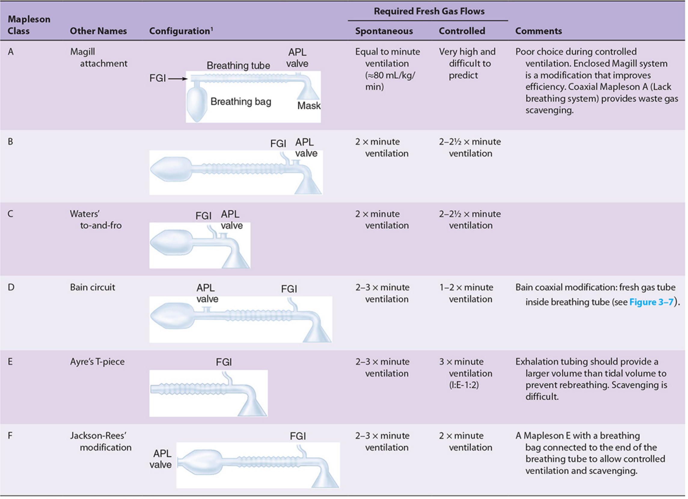
Classification Table
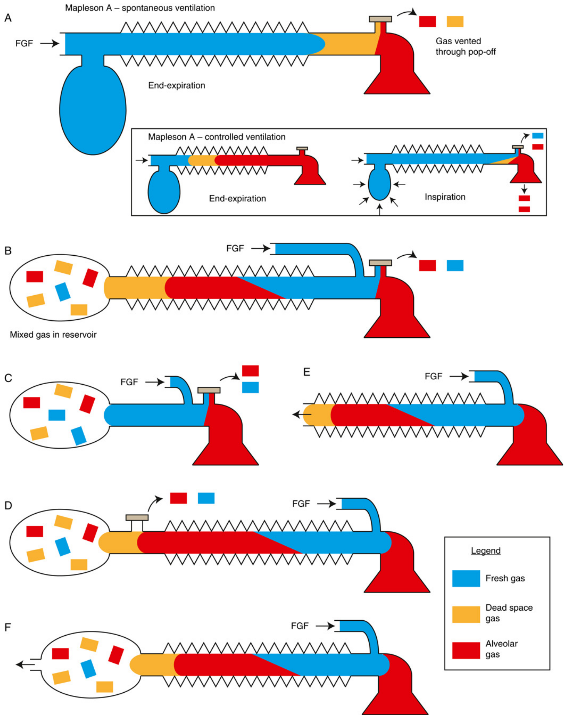
Gas Flow Diagram (A-F at end-expiration)
The Six Circuits in Detail
Mapleson A (Magill Circuit)
- Configuration: FGI at the reservoir bag end; APL valve at the patient end
- Spontaneous ventilation: Most efficient of all Mapleson circuits. FGF equal to minute ventilation (~80 mL/kg/min) suffices. During exhalation, alveolar gas travels toward the bag and is vented through the APL valve before inspiration begins; the patient then inhales only fresh gas from the tube.
- Controlled ventilation: Least efficient. The APL valve must be partially closed; alveolar gas stagnates during the expiratory phase and rebreathes during the next inspiration. FGF must be very high (>3x minute ventilation, sometimes cited as 20 L/min) to prevent CO2 rebreathing - a poor choice for controlled ventilation.
- Alias: Magill attachment
Mapleson B
- Configuration: FGI and APL valve are both near the patient end; reservoir bag at the far end
- Mixed gas (fresh + alveolar) accumulates in the reservoir bag
- Spontaneous: ~2x minute ventilation
- Controlled: ~2-2.5x minute ventilation
- Rarely used today
Mapleson C (Waters' To-and-Fro)
- Configuration: Like B, but lacks corrugated reservoir tubing - just a short connection
- FGI and APL valve near the patient; reservoir bag at the near end
- Spontaneous and controlled: ~2-2.5x minute ventilation
- Also rarely used today
Mapleson D
- Configuration: FGI near the patient end; APL valve near the reservoir bag - the exact opposite of Mapleson A
- Simply interchanging the FGI and APL valve positions of a Mapleson A produces a Mapleson D
- Controlled ventilation: Efficient. Fresh gas flow pushes alveolar gas away from the patient toward the APL valve for venting. FGF of 1-2x minute ventilation suffices.
- Spontaneous ventilation: Less efficient, requires ~2-3x minute ventilation
- Most common modification: The Bain circuit
Mapleson E (Ayre's T-Piece)
- Configuration: T-piece with FGI at the patient arm; open-ended expiratory limb (no reservoir bag, no APL valve)
- The only Mapleson circuit without a breathing bag - can only support spontaneous ventilation
- The expiratory limb volume must exceed the patient's tidal volume to prevent entrainment of room air and rebreathing
- Used in pediatrics and ICU weaning from mechanical ventilation
- Scavenging is difficult (no APL valve to attach scavenging)
- FGF: ~2-3x minute ventilation (spontaneous); ~3x minute ventilation (controlled, I:E ratio 1:2)
Mapleson F (Jackson-Rees Circuit)
- A modification of Mapleson E: an open-tail reservoir bag is added to the expiratory limb
- The bag provides a reservoir for spontaneous breathing and allows manual positive-pressure ventilation
- Primarily used in pediatrics (low resistance, minimal dead space)
- Spontaneous: ~2-3x minute ventilation
- Controlled: ~2x minute ventilation
- The open tail of the bag also allows scavenging
Functional Groups
The six circuits divide into three functional groups based on shared performance characteristics:
| Group | Members | Distinguishing Feature |
|---|---|---|
| A group | A | Best for spontaneous ventilation; worst for controlled |
| B and C group | B, C | Intermediate efficiency; rarely used |
| D, E, F group ("T-piece group") | D, E, F | Best for controlled ventilation; most widely used clinically |
Key Performance Principle
Efficiency is measured by the minimum FGF needed to prevent CO2 rebreathing. The critical variable in any Mapleson circuit is the expiratory phase: whatever gas occupies the breathing tube at end-expiration is what the patient inhales next. The 13 variables affecting CO2 rebreathing include FGF rate, minute ventilation, mode of ventilation, tidal volume, respiratory rate, I:E ratio, expiratory pause duration, peak inspiratory flow, reservoir tube volume, bag volume, ventilation mode (mask vs. ETT), and CO2 sampling site.
Memory aid for FGF requirements (spontaneous ventilation):
- Mapleson A = 1x MV (best)
- Mapleson D/E/F = 2.5x MV
- Mapleson B/C = >2.5x MV (worst)
For controlled ventilation, the order reverses: D/E/F are the most efficient; A is the least efficient.
Advantages of Mapleson Systems
- Lightweight, inexpensive, and simple
- Low resistance to gas flow
- Rapid changes in inspired agent concentration (no absorber to equilibrate)
- No CO2 absorber means no risk of volatile agent degradation (e.g., Compound A formation)
- Small and portable - useful for transport and ICU
Disadvantages
- High FGF required - less economical with carrier gas and volatile agent vs. circle system
- Poor heat and humidity conservation
- Waste gas scavenging is more difficult
- No CO2 absorption means CO2 elimination is entirely FGF-dependent
The Bain Circuit (Coaxial Mapleson D)
The Bain circuit is a coaxial modification of the Mapleson D where the fresh gas tubing runs inside the outer corrugated breathing tube. Benefits include:
- Reduced bulk
- Partial warming of inspired gases by countercurrent heat exchange with warmer expired gases in the outer tube
- APL valve is located near the bag (away from the patient), facilitating scavenging
Hazards specific to the Bain circuit: Kinking or unrecognized disconnection of the inner FGI tube causes significant rebreathing and hypercapnia. The Pethick test checks inner tube integrity: occlude the patient end until the bag fills, then release and flush with O2 - if the inner tube is intact, Venturi effect deflates the bag; if the inner tube leaks, the bag remains inflated.
Sources: Morgan & Mikhail's Clinical Anesthesiology, 7e, pp. 83-88 | Barash, Cullen & Stoelting's Clinical Anesthesia, 9e, pp. 2010-2013 | Miller's Anesthesia, 10e, pp. 2351-2353
This is a shared conversation. Sign in to Orris to start your own chat.