
Axis nd planes
What context are you asking about axes and planes?
Axis nd planes biomechanics
body planes and axes biomechanics anatomy sagittal coronal transverse
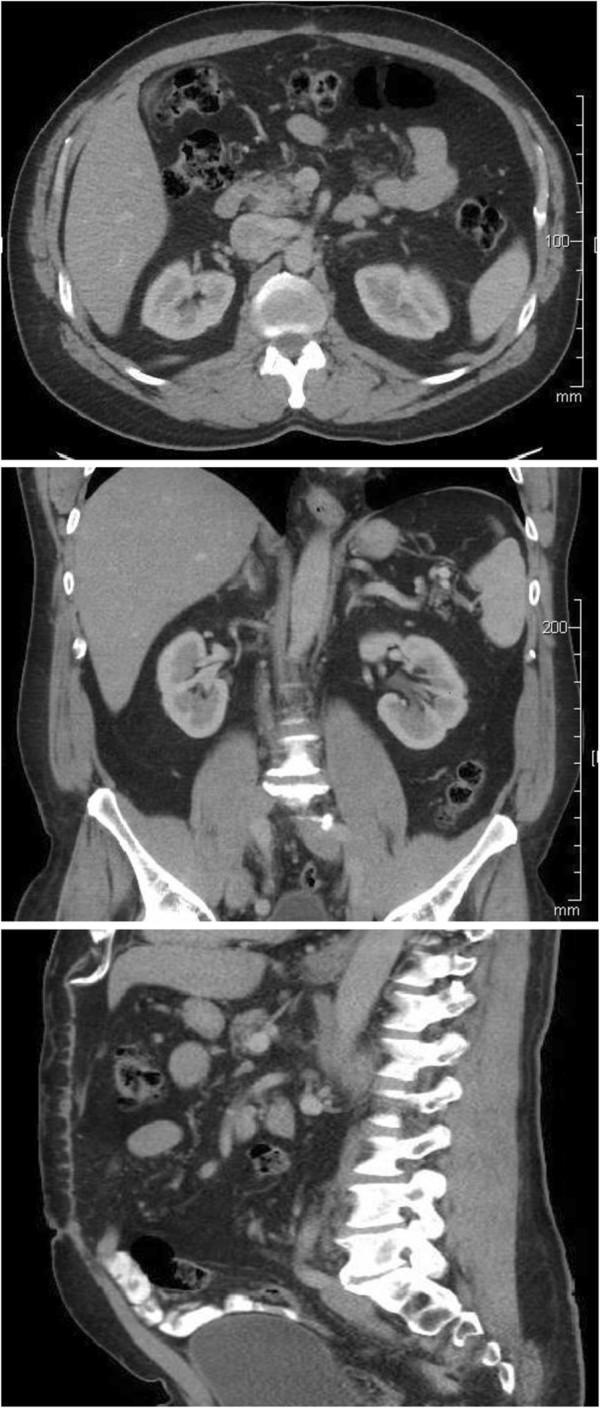
This diagnostic image displays a series of three post-operative computed tomography (CT) scans of the abdomen and pelvis in axial (top), coronal (middle), and sagittal (bottom) planes. The axial view demonstrates the transverse anatomy of the mid-abdomen, highlighting the liver, both kidneys in their retroperitoneal positions, and the vertebral body. The coronal view offers a longitudinal perspective of the abdominal cavity, showing the anatomical relationship between the liver, bilateral kidneys, spleen, and the iliac crests of the pelvis. The sagittal view provides a lateral profile of the lumbar spine and the distribution of the bowel and bladder. The images illustrate a normal anatomical configuration following the surgical resection of a large retroperitoneal mass. There is no evidence of residual cystic lesions or recurrence. Key structures such as the aorta and inferior vena cava appear in their expected midline and para-midline positions, and the bowel has returned to a normal anatomical distribution after previously being displaced. This series serves as an educational example of post-operative surveillance imaging to confirm successful surgical outcomes and the absence of disease recurrence.
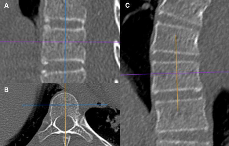
This composite diagnostic image displays three orthogonal CT (Computed Tomography) views of the human spine, demonstrating vertebral anatomy in sagittal, transverse, and coronal planes. Panel A (sagittal) shows a vertical stack of rectangular vertebral bodies with clear superior and inferior endplates and visible internal trabecular patterns. Panel B (transverse/axial) illustrates a single vertebra showing the anterior vertebral body, the posterior vertebral arch (pedicles and laminae), the central vertebral foramen for spinal cord passage, and the spinous and transverse processes. Panel C (coronal) provides a longitudinal view of the vertebral column. Cross-sectional reference lines (blue, purple, and orange) indicate the exact slicing planes and region-of-interest (ROI) orientations used for Hounsfield Unit (HU) bone density measurements. This diagnostic set is used to evaluate vertebral bone quality, cortical thickness, and anatomical orientation, specifically in the context of preoperative planning for spinal procedures such as pedicle screw fixation.
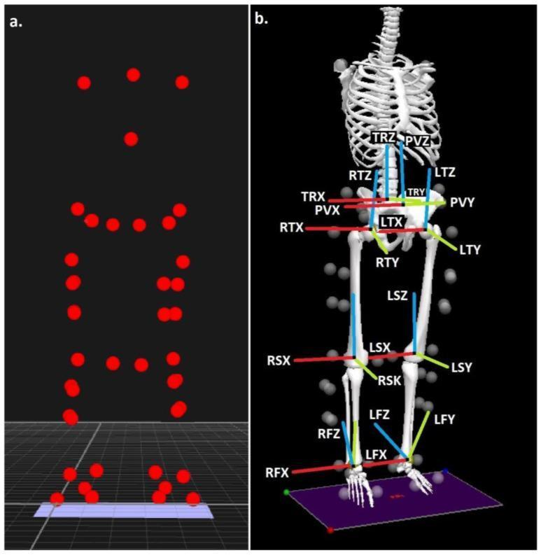
Biomechanical musculoskeletal modeling and gait analysis visualization. Panel (a) illustrates anatomical landmark locations using a point-cloud configuration of red markers. These markers correspond to key kinetic points on the human body, including the head, shoulders, trunk, pelvis, knees, and ankles. Panel (b) shows the reconstructed 3D skeletal model using the Calibrated Anatomical System Technique (CAST). The model demonstrates segmented anatomical units: Trunk (TR), Pelvis (PV), Thigh (T), Shank (S), and Foot (F), categorized into right (R) and left (L) sides. Each segment is assigned a local coordinate system with axes representing the three anatomical planes: X (sagittal/red), Y (coronal/green), and Z (transverse/blue). This model is used to calculate 6-degrees-of-freedom kinematics and joint centers (hip, knee, and ankle) for clinical biomechanics research, such as analyzing walking patterns or joint forces in specific populations like those with high BMI.
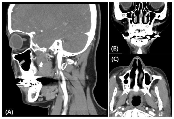
This diagnostic image set consists of three facial Computed Tomography (CT) scans presented in sagittal (A), coronal (B), and axial (C) planes. The images focus on the midface anatomy, specifically the maxillary and orbital regions. In the sagittal view (A), the eye, maxillary sinus, and anterior facial soft tissues are visible. The coronal view (B) highlights the nasal septum, turbinates, and the floor of the orbits. The axial view (C) demonstrates the transverse anatomy of the maxillary sinuses and the nasal cavity. Grey arrows in all three panels denote the anatomical location and course of the infraorbital nerve (ION) as it exits the infraorbital foramen. The scans are postoperative, following the removal of foreign body implants that were previously located near the maxillary sinuses. There is an absence of hyperdense foreign material or artifacts in the vicinity of the ION, indicating successful surgical clearance. These images serve as an educational resource for identifying the spatial relationship between the infraorbital nerve and the surrounding sinonasal and orbital bony structures in multi-planar imaging.
Anatomical Position - The Reference Standard
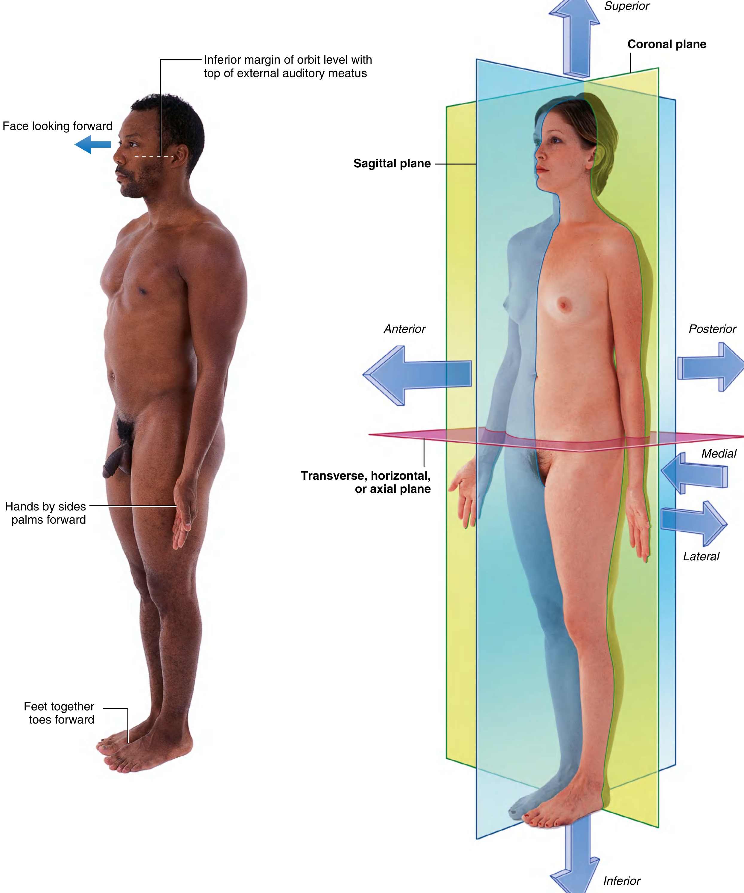
The Three Cardinal Planes
| Plane | Also Called | Division of Body | Movements Occurring IN This Plane |
|---|---|---|---|
| Sagittal | Anteroposterior plane | Left and right halves | Flexion, Extension |
| Frontal | Coronal plane | Anterior and posterior halves | Abduction, Adduction |
| Transverse | Horizontal / Axial plane | Superior and inferior halves | Internal/External Rotation |
- The median (mid-sagittal) plane is the specific sagittal plane that divides the body into equal left and right halves.
- Any plane parallel to the median sagittal plane is simply called a "sagittal plane."
The Three Cardinal Axes
| Axis | Also Called | Lies at Intersection of | Movement Around This Axis |
|---|---|---|---|
| Vertical (Longitudinal) | Craniocaudal axis | Coronal plane + Sagittal plane | Internal / External Rotation |
| Sagittal (Anteroposterior) | AP axis | Sagittal plane + Transverse plane | Abduction / Adduction |
| Transverse (Horizontal) | Mediolateral axis | Coronal plane + Transverse plane | Flexion / Extension |
Key rule: Movement always occurs in a plane and around an axis perpendicular to that plane.
Planes, Axes, and Movements - Summary Table
| Movement | Plane of Motion | Axis of Rotation |
|---|---|---|
| Flexion / Extension | Sagittal plane | Transverse (mediolateral) axis |
| Abduction / Adduction | Frontal (coronal) plane | Sagittal (anteroposterior) axis |
| Internal / External Rotation | Transverse plane | Vertical (longitudinal) axis |
| Circumduction | Combination of sagittal + coronal | Multiple axes sequentially |
Degrees of Freedom (DOF)
- Uniaxial (1 DOF) - movement in one plane about one axis. Example: hinge joint (elbow - flexion/extension only)
- Biaxial (2 DOF) - movement in two planes. Example: condyloid/saddle joint (wrist - flexion, extension, abduction, adduction)
- Multiaxial (3 DOF) - movement in all three planes. Example: ball-and-socket joint (hip, shoulder - all movements including rotation)
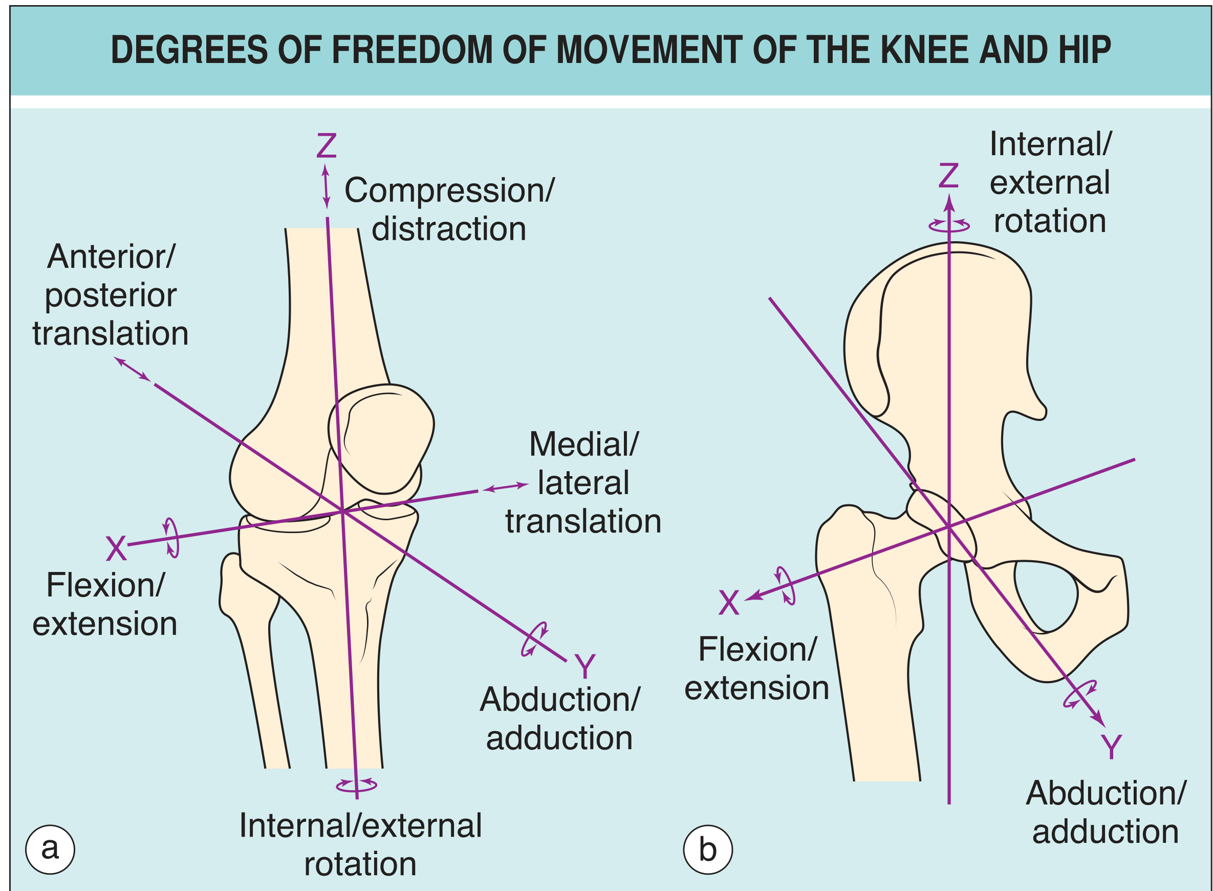
Clinical Reference System (CRS)
- Sagittal plane motion - flexion and extension
- Away from / toward midsagittal plane - abduction and adduction
- Rotation about the long axis - internal/external rotation or supination/pronation
- Circumduction - combination of flexion-extension + abduction-adduction
Axis Deviations in Clinical Practice
- Varus deformity - axis deviation is concave toward the vertical body axis (e.g., genu varum = bow-legs)
- Valgus deformity - axis deviation is convex to the body axis (e.g., genu valgum = knock knees)
- Recurvation - hyperextension at a joint
- Antecurvation - abnormal forward angulation