
Upper 3rd molar impacted surgery steps
upper third molar impaction surgical removal steps
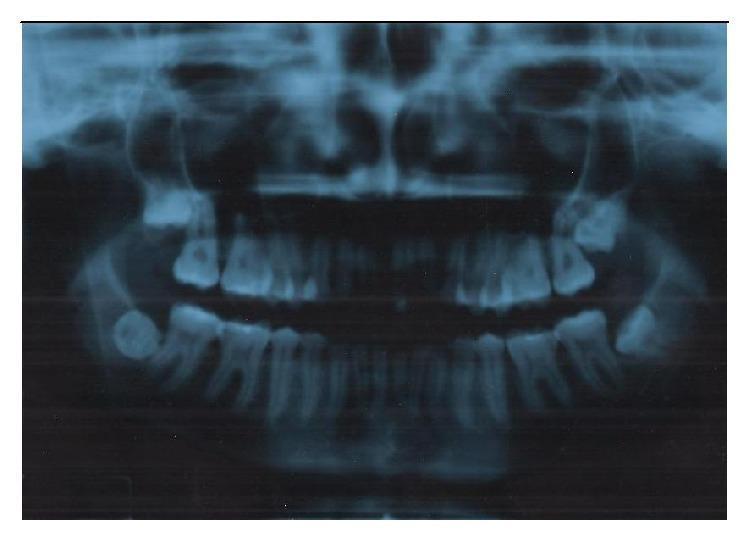
This diagnostic image is an orthopantomogram (panoramic X-ray) of the human maxilla and mandible, illustrating several dental anomalies and surgical landmarks. The primary educational focus is on the impaction of all four third molars (teeth 18, 28, 38, and 48). In the upper right quadrant, the third molar (18) exhibits vertical impaction in close proximity to the floor of the maxillary sinus. In the upper left, the third molar (28) shows mesioangular impaction. Both mandibular third molars (38 and 48) demonstrate horizontal impaction, with tooth 38 showing a Pell and Gregory Class 2 depth and tooth 48 displaying significant vestibularization. The radiograph also allows for the assessment of root morphology across the dental arches and the spatial relationship between the mandibular molars and the inferior alveolar nerve canal. This imaging is characteristic of preoperative assessment in oral and maxillofacial surgery for planning complex extractions.
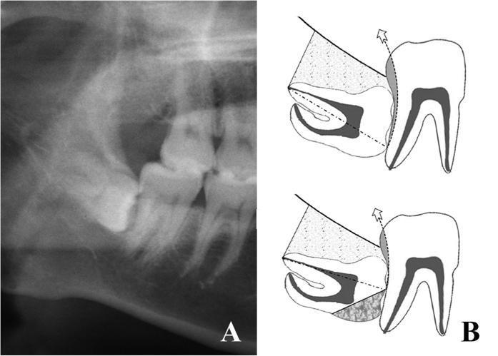
The visual consists of two parts: (A) a diagnostic orthopantomogram (OPG) and (B) a technical surgical sketch, both illustrating a high-risk mandibular third molar (tooth 48) impaction. Image A shows tooth 48 in a horizontal position, deeply embedded within the mandibular bone with its crown directly abutting the distal surface of the adjacent second molar. The roots are positioned posteriorly, and the crown is partially obscured by the alveolar bone, classified as risk degree III. Image B provides a schematic of the same tooth demonstrating 'Risk Degree III' surgical considerations. The sketch illustrates that even after a half-crown sectioning procedure and complete bone removal (indicated by stippled areas), high resistance remains from the adjacent second molar. A dashed line indicates the long axis of the impacted tooth, while a curved arrow indicates the required extraction pathway. Shaded regions highlight mechanical obstruction points. This content is designed for oral and maxillofacial surgery education, focusing on surgical planning for complex impactions involving high adjacent tooth resistance and the assessment of extraction pathways.
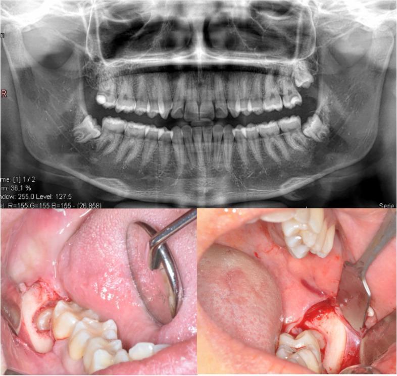
This composite medical image illustrates a clinical case of impacted mandibular third molars and the corresponding surgical intervention. The upper panel displays an orthopantomogram (panoramic radiograph) showing a full permanent dentition. Bilateral, horizontally impacted mandibular third molars (teeth 38 and 48) are clearly visible, with their crowns oriented mesially against the second molars and roots in close proximity to the inferior alveolar nerve canal. The lower panels provide intraoral clinical photographs of the surgical site. The left image shows a reflected full-thickness envelope flap in the mandibular posterior region, utilizing a dental mirror for retraction to expose the partially erupted third molar and surrounding gingival tissues. The right image depicts the active surgical field with further bone removal (osteotomy), showing the exposed crown of the impacted tooth, minor bleeding expected during the procedure, and a periosteal elevator or retractor used to maintain visibility. This image serves as an educational tool for oral and maxillofacial surgery, demonstrating the radiographic diagnosis and initial surgical steps for third molar extraction.
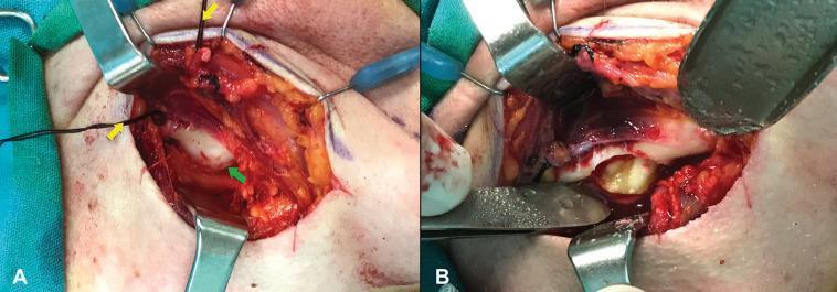
Two-panel clinical photograph illustrating an extraoral surgical approach for an ectopic mandibular third molar. Figure A shows the surgical site after a submandibular incision and elevation of the periosteum of the mandibular body. Yellow arrows indicate black silk ligatures on the facial artery and vein, used to safely retract the marginal mandibular branch of the facial nerve from the operative field. A green arrow points to a localized bony expansion on the mandibular surface representing the impaction site. Figure B depicts the same site following a buccal plate osteotomy. The removal of the overlying bone reveals an impacted tooth (yellowish-white structure) surrounded by dark, cystic soft tissue, later identified as a dentigerous cyst. This sequence demonstrates maxillofacial surgical techniques for managing deep mandibular impactions while protecting vital neurovascular structures, specifically the facial nerve (Cranial Nerve VII).
upper maxillary third molar impaction surgical extraction steps technique 2024
https://uomustansiriyah.edu.iq/media/lectures/3/3_2021_10_01…
maxillary wisdom tooth flap incision buccal approach upper molar
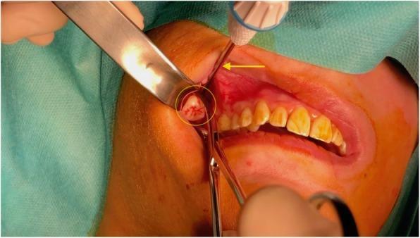
Clinical photograph of an intraoral surgical procedure for the retrieval of a displaced maxillary third molar (wisdom tooth). The surgical field shows the right posterior superior buccal sulcus of a patient under anesthesia. A yellow circle highlights the crown of the displaced tooth being extracted from the soft tissue. A yellow arrow points to a 12 Gauge bone trocar inserted through a small incision in the buccal sulcus to provide cranial stabilization and support. Surgical instrumentation is visible, including a metal retractor reflecting the cheek for visualization and a pair of Kelly forceps grasping the tooth for retrieval. The surrounding gingival tissue shows expected perioperative erythema and inflammation. The adjacent maxillary teeth are visible, demonstrating moderate intrinsic staining. This image illustrates a combined radiologic-surgical approach for managing teeth displaced into deep facial spaces like the infratemporal fossa.
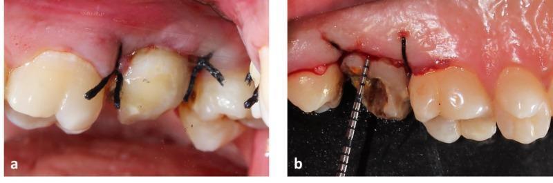
This composite clinical photograph displays two intraoral views of the upper left maxillary quadrant during a crown lengthening procedure for a second molar. Image (a) presents the buccal view, showcasing the placement of multiple simple interrupted sutures using dark-colored 3-0 braided silk. The sutures are positioned interdentally to approximate the gingival flap margins and adapt the soft tissue tightly against the cervical area of the teeth. Image (b) shows the palatal view of the same second molar, revealing a tooth with significant structural loss and dark carious discoloration. A calibrated periodontal probe is visible, measuring the clinical crown height or biological width. The surrounding gingival margins exhibit postoperative erythema and surgical irregularity consistent with recent internal bevel incision and flap elevation. These images demonstrate the surgical management of a compromised tooth to increase clinical crown height for future prosthetic restoration, emphasizing flap stabilization and periodontal measurement.
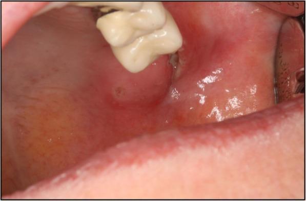
This clinical photograph is an intraoral image showing the upper left maxillary region of a 67-year-old patient. The visual focus is on the soft tissue surrounding a wisdom tooth (third molar). The gingiva and adjacent buccal mucosa exhibit pronounced erythema and edema, indicating acute inflammation. A significant feature is a localized soft tissue laceration or ulcerative lesion situated immediately distal and lateral to the tooth, with an irregular border and a central depression. The tooth appears partially erupted or impacted within the swollen gingival tissue. Clinical context suggests these findings are the primary intraoral manifestation of tularemia, associated with severe systemic symptoms like high fever and elevated C-reactive protein. This image serves as a clinical example of atypical oral infections and the importance of correlating local lesions with systemic inflammatory markers in oral surgery and infectious disease diagnostics.
Surgical Removal of an Impacted Upper Third Molar (Maxillary Wisdom Tooth)
Pre-operative Assessment
- History of pain, pericoronitis, caries, or adjacent tooth resorption
- Mouth opening (assess for trismus), oral aperture size, position of coronoid process (limits access in upper third molars)
- Presence of pathology (cyst, tumour)
- Periapical X-ray
- Orthopantomogram (OPG) - primary imaging
- Occlusal X-ray
- PNS (paranasal sinus) view - if sinus involvement suspected
- CT scan - if associated pathology, complex angulation, or suspected sinus proximity
- State of eruption: fully erupted / partially erupted / unerupted
- Angulation: vertical, mesioangular, distoangular, horizontal, transverse (buccal/palatal)
- Depth: relationship to occlusal plane and adjacent molar
- Root morphology: conical single root (easier) vs. divergent/curved roots (harder)
- Position deep to the occlusal plane of the second molar = increased difficulty
- Divergent, curved, or hypercementosed roots
- Restricted mouth opening / small oral aperture
- Crown positioned above the level of adjacent molar root apices (risk of displacement into infratemporal fossa)
- Close proximity to maxillary sinus (risk of oro-antral communication)
Step 1 - Patient Positioning
- Patient is semi-reclined with the maxillary occlusal plane at ~45° to the floor (compared to the mandible where it is parallel to the floor)
- Instruments are arranged in the order of intended use on a separate trolley
Step 2 - Local Anaesthesia
- Infiltration technique (maxillary third molars do not require nerve blocks in most cases due to the cancellous nature of maxillary bone)
- Buccal infiltration posterior to the second molar at the tuberosity
- Greater palatine nerve block or palatal infiltration for palatal gingiva
- Current practice: Articaine 4% with adrenaline 1:100,000 (1.8-2 mL per site) is preferred for maxillary surgery due to its superior diffusion through bone
- Allow 3-5 minutes for full anaesthetic effect
Step 3 - Incision and Flap Design
- Straight incision beginning in the middle of the crest of the maxillary tuber, extending anteriorly to the middle of the distal surface of the second molar
- The blade follows the gingival margin buccally
- A triangular (three-sided) flap is made by adding a vertical release incision anteriorly at the mesial aspect of the second molar, directed obliquely into the buccal vestibule
- This provides wider exposure of the tuberosity and surrounding bone
Step 4 - Flap Elevation
- A Howarth's periosteal elevator (or similar) is used to raise a full-thickness mucoperiosteal flap
- Elevate buccally to expose the alveolar bone overlying the impacted tooth
- Palatal soft tissue is gently retracted (not usually elevated as a separate flap)
- A retractor (e.g. Austin or Bowdler-Henry) is placed to protect the flap and maintain visibility
Step 5 - Bone Removal (Osteotomy)
- A straight handpiece with a round or fissure bur (e.g. No. 6 round bur or 702 bur) under copious saline irrigation is used
- Bone is removed from the buccal, occlusal, and distal aspects to expose:
- The crown of the impacted tooth
- The cervical line (cemento-enamel junction)
- The upper third of the root(s)
- Lingual bone is not removed (risk of oro-antral communication is buccal/distal; lingual bone in the maxilla is thin and fragile)
- Amount of bone removed depends on depth and angulation:
- Superficial impaction: minimal bone removal
- Deep impaction: more extensive bone removal required; consider tooth sectioning
Step 6 - Tooth Delivery (Luxation and Elevation)
- Apply the elevator into the periodontal space between the tooth and the socket wall
- Use rotational and lever movements to expand the socket and luxate the tooth
- Primary movement is distally and buccally (away from the maxillary sinus)
- Dental forceps (upper wisdom tooth forceps - cowhorn or straight upper molar pattern) can be applied after adequate luxation
- Movements: buccal-palatal rocking, then traction outward (downward and buccally)
Step 7 - Tooth Sectioning (if needed)
- Divergent or curved roots
- Deep impaction where bone removal alone is insufficient
- Crown above the level of adjacent root apices (to avoid displacement)
- Section the tooth at the cervical region (crown-root junction) with a fissure bur
- Remove the crown first
- Then remove each root separately
- Or section through the furcation if multi-rooted, removing roots individually
Step 8 - Wound Toilet (Socket Debridement)
- Remove all bone fragments, debris, and follicular tissue with a curette
- Irrigate the socket copiously with sterile saline
- Check for any oro-antral communication (ask the patient to perform the Valsalva maneuver with their nose pinched - observe for air/bubbles in the socket)
- If oro-antral communication is present: close primarily with a buccal advancement flap (Rehrmann flap) or refer immediately
Step 9 - Haemostasis
- Compress the socket with gauze for 2-3 minutes
- If bleeding persists: bone wax, oxidized cellulose (Surgicel), or a resorbable haemostatic agent
- Check that the bone edges are smooth (file if sharp)
Step 10 - Flap Closure and Suturing
- Reposition the flap to its original anatomical position
- Suture with 3-0 or 4-0 resorbable sutures (e.g. Vicryl) or silk (removed at 5-7 days)
- An interrupted suture is placed at the distal end of the incision first, then additional sutures as needed
- Sutures serve to: stabilize the flap, achieve haemostasis, and close any potential oro-antral communication
Post-operative Instructions & Prescriptions
- Bite on gauze for 30-45 minutes
- Ice packs to the cheek for 24-48 hours (reduces swelling)
- Analgesics (ibuprofen 400-600 mg or paracetamol)
- Antibiotics if indicated (immunocompromised, pericoronal infection, intraoperative complications)
- Avoid smoking, spitting, and hard foods for 48-72 hours
- No vigorous rinsing for 24 hours; gentle chlorhexidine rinse from day 2
- Review at 5-7 days for suture removal (non-resorbable)
Intraoperative Complications
| Complication | Cause | Management |
|---|---|---|
| Displacement into maxillary sinus | Conical roots + excessive apical force | Caldwell-Luc approach for retrieval |
| Displacement into infratemporal fossa | Inadequate buccal flap, crown above adjacent root apices | Haemostat/Allis forceps retrieval; if inaccessible - refer to maxillofacial |
| Oro-antral communication | Roots projecting into sinus | Primary closure with Rehrmann buccal advancement flap |
| Root fracture | Divergent/hypercementosed roots | Elevate fragments carefully; if deep and near sinus - leave and observe |
| Tuberosity fracture | Excessive force on fused/large tuberosity | Stabilize with splint; allow healing before extraction |