
Stem placed in thr guidelines
Could you clarify what you mean by 'Stem placed in the guidelines'?
femoral stem placement total hip arthroplasty
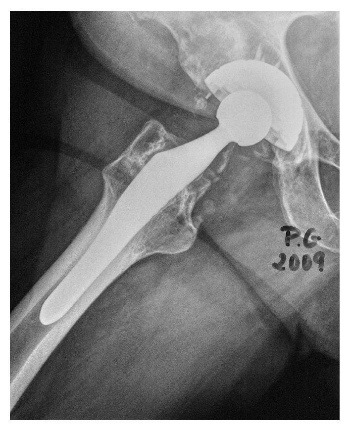
This diagnostic X-ray shows a right total hip arthroplasty (THA) in a four-year follow-up status. The visual content demonstrates an original cementless ABG I prosthesis consisting of a metallic femoral stem and an acetabular cup. The femoral stem is anatomically positioned within the medullary canal of the proximal femur, showing stable osseointegration. A metallic femoral head is articulated with the acetabular cup. Notably, there is evidence of post-surgical changes in the periprosthetic acetabular region where radiodense material indicates the placement of bone graft to address previous osteolysis. The proximal femur shows some signs of bone remodeling, including mild radiolucency in the superior metaphyseal region (Gruen zones 1 and 7), which is suggestive of stress shielding—a common phenomenon where the rigid metal implant alters normal load distribution. The alignment of the implant components appears stable with no signs of hardware loosening, migration, or fracture.
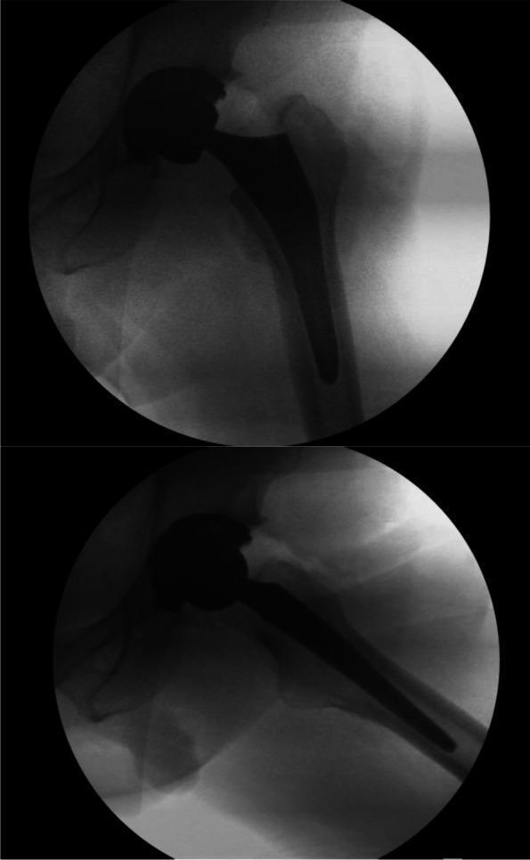
Two intraoperative fluoroscopic (X-ray) views of a total hip arthroplasty (THA) demonstrate final implant placement and orthopedic hardware positioning. The imaging shows a radiodense femoral component consisting of a tapered metallic stem inserted into the medullary canal of the proximal femur and a spherical femoral head. The femoral head is articulating with an acetabular cup, which appears as a faint, radiolucent crescent within the pelvic acetabulum. Anatomical landmarks including the greater trochanter and lesser trochanter are visible, serving as reference points for assessing leg length and offset. The bone-implant interface displays no significant radiolucency, suggesting stable initial fixation. The positioning is consistent with standard surgical parameters for alignment and joint restoration. These images are used in surgical education to illustrate the confirmation of implant seatedness and overall joint reconstruction during the final stages of a direct anterior approach (DAA) hip replacement.
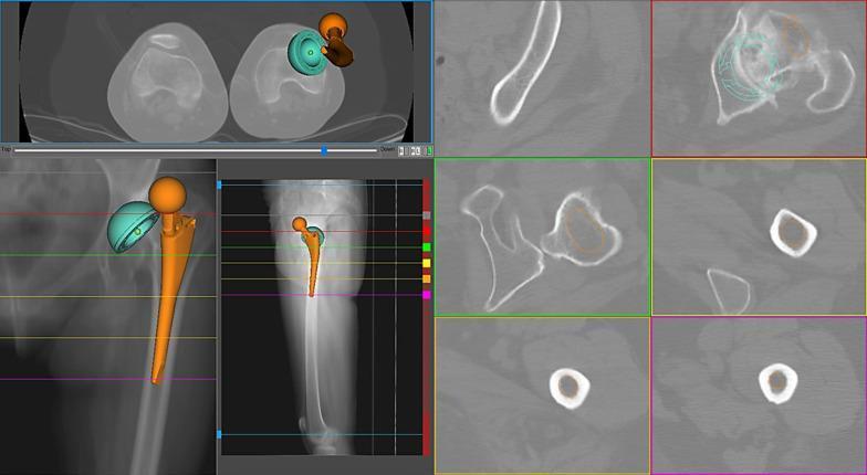
This composite diagnostic image illustrates an orthopedic preoperative planning simulation for a total hip arthroplasty (THA) in a 46-year-old female with Crowe III developmental dysplasia of the hip. The visualization combines multiple modalities: a full-length coronal X-ray of the femur showing the anatomical stem placement (orange), and several axial CT scan slices providing cross-sectional views of the femoral canal and pelvis. A 3D anatomical model of the prosthesis, including a turquoise acetabular cup and an orange femoral stem with a spherical head, is superimposed on the radiographic data. Key features shown include the native femoral anteversion (60°) and the simulated cup anteversion (16°). The layout demonstrates the spatial relationship and fit of the implant at various anatomical levels. The simulation evaluates parameters such as combined anteversion, offset restoration, and canal filling. In this specific case, the reconstruction is categorized as unacceptable because the combined anteversion exceeds the clinical limits established by Dorr and Widmer, highlighting the challenges of anatomical stem designs in patients with severe femoral dysplasia.
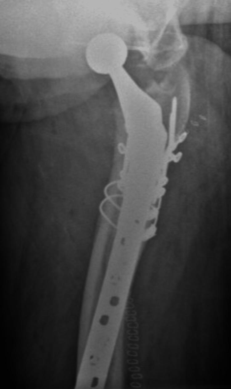
This axial X-ray of the right hip demonstrates a postoperative view of a periprosthetic femoral fracture managed with internal fixation. A primary total hip arthroplasty (THA) is visible, featuring a femoral stem and a prosthetic femoral head articulating within the acetabulum. The fracture site, primarily involving the proximal femur/greater trochanter region, is stabilized with a long lateral locking plate and screw construct extending distally along the femoral shaft. Multiple cerclage wires encircle the proximal femur to provide additional circumferential compression and stability for the fracture fragments around the pre-existing prosthesis. The imaging shows successful anatomical alignment of the bone and hardware placement, which is characteristic of the management of Vancouver B1 or C type periprosthetic fractures where the primary stem remains stable. This clinical image is educational for understanding orthopedic revision strategies and the integration of osteosynthesis hardware with existing arthroplasty components.
femoral stem placement guidelines total hip arthroplasty alignment valgus varus neutral
https://hipandkneebook.com/tha-chapters/2017/4/18/stem-place…
Femoral Stem Placement Guidelines in Total Hip Arthroplasty (THA)
1. Coronal Alignment (Varus/Valgus)
- Neutral is defined as 0° deviation from the femoral shaft axis; acceptable range is generally within ±2° varus/valgus
- Varus malposition is the most common error - it occurs because bending forces during insertion push the stem medially. A lateral starting point during broaching helps prevent this
- Varus stems increase loading stress at the cement-bone interface (cemented) and predispose to loosening and periprosthetic fracture
- Valgus position also unacceptable - increases leg length and alters load distribution
- Published data show ~56.5% of stems placed neutral, ~38% in acceptable 0-2° deviation, and ~5% with >2° deviation needing correction (PMC study via DAA approach)
2. Femoral Anteversion
- Target: approximately 15° of anteversion (matching native femoral neck anteversion)
- For press-fit (cementless) stems, native femoral anatomy largely dictates the version - the surgeon has limited control
- For cemented stems and modular stems (e.g., S-ROM), the surgeon can independently set version
- A common intraoperative reference: align to the posterior cortex of the femoral neck at the resection level
- Rotate the first broach to match anteversion (~15°) before sequential broaching
3. Medial Offset Restoration
- Offset = horizontal distance from the center of the femoral head to the femoral shaft axis
- Determines abductor tension and hip stability
- Should be planned preoperatively using digital templating
- Standard vs. high offset stems: high offset lateralizes the center of rotation, improving abductor tension and reducing dislocation risk - but excessive lateralization causes trochanteric bursitis
- Neck-shaft angle of the native femur guides stem selection
4. Leg Length (Vertical Height)
- Determined by where the center of the femoral head sits relative to the pelvis
- Target: restore to contralateral side (equality within ~5-10 mm)
- Leg length increases with:
- Incomplete stem seating ("potted stem")
- Valgus stem position (tip contacts medial cortex)
- Larger femoral head offset options (+4, +8 mm heads)
- Leg length decreases with varus positioning
- Intraoperative check: fluoroscopy, trial reduction with measurement of limb lengths, comparison to preoperative template
5. Stem Seating Depth
- Stem must be seated to the predetermined templated depth
- Cemented technique: cement restrictor placed ~1 cm below the stem tip to allow pressurization; cement flows into cancellous bone rather than tracking distally
- Uncemented technique: broach until the implant achieves a firm press-fit with cortical contact; confirmed by absence of subsidence or toggle on trial
- For revision stems: the stem should engage the diaphysis beyond any defect for both alignment and fixation (per Rockwood & Green, 10th ed.)
6. Key Intraoperative Checks Before Final Implantation
- Hip does not sublux/dislocate with mild adduction, internal rotation, and flexion
- Neck length and offset match contralateral preoperative template
- Component anteversion is appropriate
- Short external rotators and posterior capsule can be repaired to their insertion
- Leg lengths are equal (or intentional asymmetry is acceptable)
Summary Table
| Parameter | Target | Common Error | Consequence |
|---|---|---|---|
| Coronal alignment | Neutral (0°) | Varus | Loosening, periprosthetic Fx |
| Anteversion | ~15° | Excessive IR or ER | Dislocation/impingement |
| Medial offset | Match native/template | Under-offset | Abductor weakness, instability |
| Leg length | Equal to contralateral | Lengthening | Nerve palsy, gait abnormality |
| Seating depth | Template-defined | Proud/potted | LLD, instability |
- AOFoundation THA surgical reference on coronal alignment and cementing technique
- Hip & Knee Book - Stem Placement for offset, leg length, and anteversion goals
- PMC DAA stem position study showing real-world placement accuracy data
- Rockwood & Green's Fractures in Adults, 10th ed. (2025) - revision stem diaphyseal engagement guidance