
Acl tunnel entry point
ACL reconstruction tunnel entry point tibial femoral
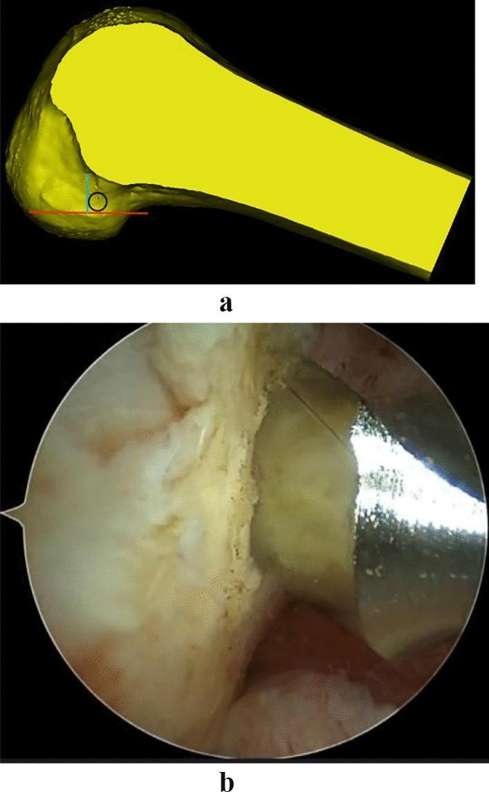
This composite image illustrates the surgical planning and intraoperative execution of femoral tunnel positioning during Anterior Cruciate Ligament (ACL) reconstruction. Panel A presents a 3D anatomical diagram of the distal femur. A red horizontal line marks the lowest point of the femoral cartilage margin. A blue vertical line extends from this base, perpendicular to the tibial plateau orientation. A black circle, representing a hollow drill, is placed tangential to both lines to identify the I.D.E.A.L. femoral tunnel entry point. Panel B shows a corresponding intraoperative arthroscopic view of the knee joint. The image captures the surgical field where the lateral femoral condyle is visible. A metallic surgical instrument, specifically a hollow drill or guide, is positioned against the bone surface to begin the creation of the femoral bone tunnel. This visual demonstrates the clinical application of the 'high flexion femur preservation' positioning method, ensuring anatomical graft placement relative to the femoral condylar landmarks and resident ACL stumps.
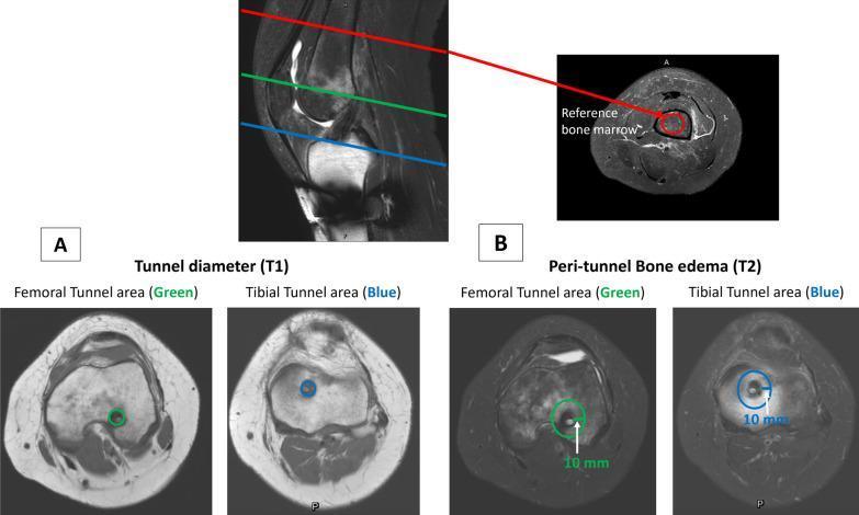
This diagnostic imaging composite illustrates the methodology for assessing graft-bone tunnel interfacial healing following ACL reconstruction. The top image shows a sagittal T2-weighted MRI of the knee with reference lines for transverse sections. Section A displays T1-weighted transverse views used to measure the bone tunnel diameter at the femoral (green circle) and tibial (blue circle) entry points. Section B utilizes T2-weighted transverse views to assess peri-tunnel bone edema. In these T2 images, circular regions of interest (ROI) with a 10 mm diameter are centered on the femoral and tibial tunnels to quantify signal hyperintensity, indicative of edema. An additional transverse view of the middle third of the femoral shaft (red circle) serves as a reference point for normal bone marrow signal intensity. This normalization allows for the objective calculation of peri-tunnel edema changes. The content is designed for orthopedic and radiological education, focusing on post-surgical ligament reconstruction monitoring and tendon-to-bone healing metrics.
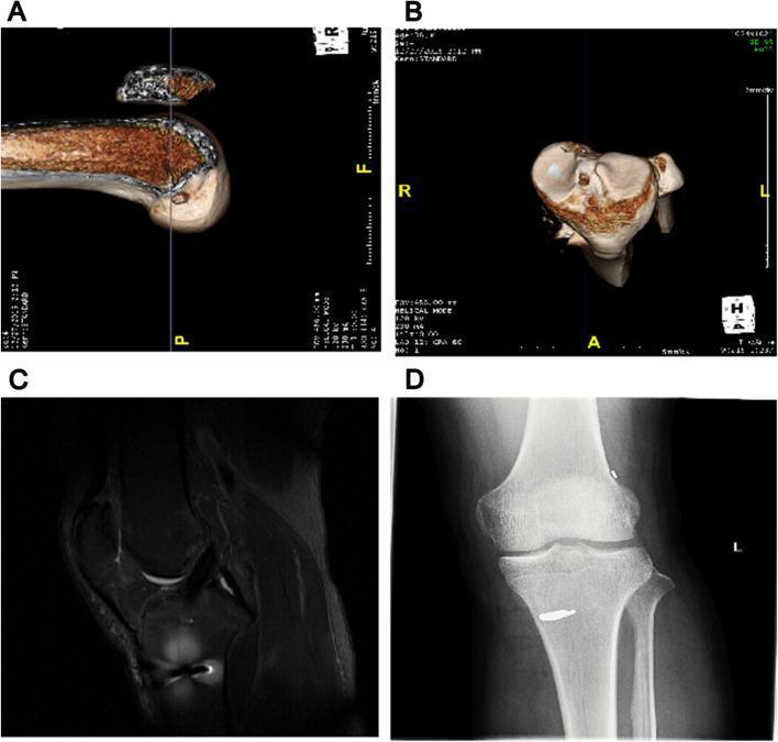
This composite of four clinical diagnostic images illustrates the postoperative evaluation of an anterior cruciate ligament (ACL) reconstruction. Panels A and B present 3D-reconstructed CT images of the distal femur. Panel A shows a longitudinal view of the femoral tunnel, appearing as a cylindrical void within the lateral femoral condyle. Panel B provides a transverse (axial) view, demonstrating the precise circular entry point and orientation of the bone tunnel. Panel C is a sagittal T2-weighted MRI of the knee joint, displaying the ACL graft as a continuous, low-signal (dark) band extending from the tibia to the femur, which suggests a healthy graft without signs of rupture or cyclops lesions. Panel D is an anteroposterior X-ray of the knee, revealing the metallic fixation hardware. A radiopaque interference screw is clearly visible within the tibial tunnel, showing proper alignment and cortical anchoring without evidence of migration or loosening. Collectively, these images demonstrate standard postoperative monitoring for tunnel positioning, graft integrity, and hardware stability in orthopedic sports medicine.
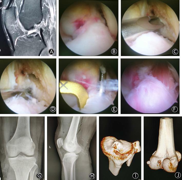
A multi-modal educational image series detailing a single-bundle anterior cruciate ligament (ACL) reconstruction procedure. Panel (A) shows a sagittal MRI of a ruptured ACL. Panels (B-F) provide an intraoperative arthroscopic sequence: (B) visualization of the ACL rupture; (C) marking the femoral I.D.E.A.L. point and positioning the Kirschner wire; (D) assessment of the femoral tunnel; (E) placement of the tibial drill guide at the remnant footprint; and (F) final graft fixation passing through the center of the ACL stump. Panels (G-H) are postoperative anteroposterior and lateral radiographs showing the hardware position, including the TightRope button. Panels (I-J) present 3D CT reconstructions demonstrating the precise anatomical entry and exit points for the tibial and femoral bone tunnels respectively. The content is designed for orthopedic surgical training, focusing on anatomical tunnel placement and the preservation of ACL remnants during reconstruction.
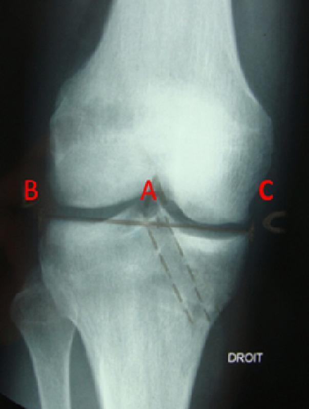
This anterior-posterior (AP) radiograph of a human right knee demonstrates a post-operative assessment of an anterior cruciate ligament (ACL) reconstruction. The image focuses on the evaluation of the tibial tunnel position using the Romano method. Key anatomical structures visible include the distal femur, proximal tibia, fibula, and the knee joint space. A radiolucent tibial tunnel is clearly visible, demarcated by dashed lines, following an oblique trajectory from the medial aspect of the proximal tibia toward the intercondylar eminence. Lettered annotations (A, B, and C) facilitate the measurement of the tunnel's exit point relative to the tibial plateau's width (B-C). Specifically, point A indicates the center of the tunnel's articular exit near the medial tibial spine. Surgical hardware, likely representing metallic staples or sutures, is faintly visible near the joint line and lateral femoral cortex. This diagnostic image is used in orthopedic surgery to ensure anatomical tunnel placement, which is critical for graft isometricity and preventing post-operative graft impingement or failure.
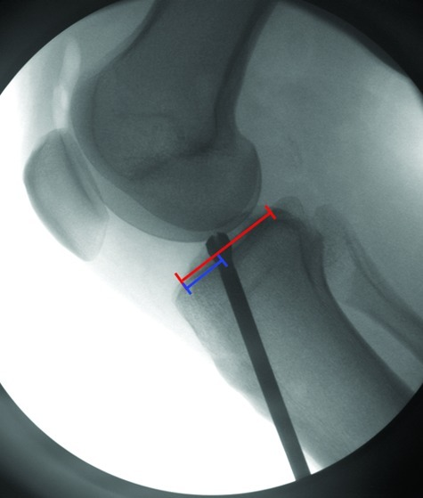
**Imaging Modality:** Intra-operative fluoroscopy. **Anatomical Region:** Lateral view of the knee joint, including the distal femur, proximal tibia, and patella. **Procedure & Context:** Anterior Cruciate Ligament (ACL) reconstruction. The image captures the intra-operative phase of tibial tunnel preparation. **Key Landmarks & Observations:** - **Skeletal structures:** The femoral condyles and tibial plateau are visible in a lateral profile. - **Surgical Instrumentation:** A radiopaque rigid reamer or guide pin is positioned within the proximal tibia, oriented toward the anatomical footprint of the ACL on the tibial plateau. - **Quantitative Overlays:** Red and blue measurement calipers are superimposed on the tibial plateau to assess the sagittal positioning and diameter of the tibial tunnel or the trajectory of the hardware relative to the posterior cruciate ligament (PCL) and anterior tibial cortex. - **Hardware Alignment:** The image evaluates the posterior-to-anterior positioning of the reamer/tunnel to ensure anatomical graft placement and avoid impingement. **Clinical Significance:** This fluoroscopic view is critical for confirming the precise entry point and trajectory of the tibial tunnel during ligament reconstruction to prevent graft failure or knee instability.
ACL reconstruction tibial tunnel entry point anatomy landmarks
ACL Tunnel Entry Points
Tibial Tunnel Entry Point
- Approximately 15.9 mm below the medial tibial plateau and 9.8 mm posteromedial to the medial margin of the tibial tubercle
- This is the optimal starting point to allow proper tunnel angle and anatomic femoral tunnel positioning
- Anterior: Parsons' knob (anterior intercondylar eminence)
- Medial: Medial intercondylar ridge
- Lateral: Anterior horn of the lateral meniscus
- Posterior: Anterior borders of the medial and lateral tubercles (retroeminence ridge)
- The center lies approximately 7 mm anterior to the PCL, medial to the midpoint of the anterior horn of the lateral meniscus attachment
Femoral Tunnel Entry Point
Transtibial technique (older/traditional)
- The femoral guide passes through the tibial tunnel, so the tibial entry dictates the femoral position - this often results in a non-anatomic, anterior femoral tunnel placement
Anteromedial (AM) portal technique (preferred anatomic approach)
- Entry is through the anteromedial arthroscopic portal with the knee in high flexion (120°)
- The drill targets the center of the native ACL femoral footprint on the lateral femoral condyle
- Located at approximately 43% of the proximal-to-distal distance of the lateral femoral notch wall
- Centered over the lateral bifurcate ridge (also called the resident's ridge)
- No native ACL fibers are located anterior to the lateral intercondylar ridge
- The posterior edge of the footprint sits approximately 2.5 mm from the posterior articular cartilage
- A horizontal line from the distal cartilage margin and a vertical line from the posterior cartilage margin intersect at the tunnel center
Outside-in (retrograde) technique
- Entry point is through the lateral femoral cortex, accessed via a small incision lateral to the knee, using a retrograde reamer
Key Clinical Points
| Parameter | Tibial Tunnel | Femoral Tunnel |
|---|---|---|
| Entry site | Anteromedial tibial cortex, ~3-4 cm below joint | Lateral femoral cortex (outside-in) or AM portal |
| Articular target | Center of ACL tibial footprint | Center of ACL femoral footprint |
| Angle | ~55-65° to tibial plateau (sagittal) | ~45° to femoral shaft |
| Common error | Too anterior or too posterior placement | Anterior malposition (most common failure cause) |
Visual Reference