
describe in detail the anatomy of the thoracic cage
thoracic cage anatomy ribs sternum diagram
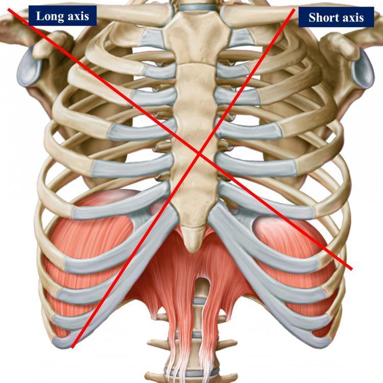
This anatomical diagram provides an anterior view of the human thoracic cage and upper abdominal musculature. The skeletal framework consists of the sternum (manubrium, body, and xiphoid process), articulating ribs with prominent costal cartilages, and components of the shoulder girdle, including the clavicles and glenoid cavities. Two intersecting red lines represent the long and short axes used for cardiac surface projection and surgical landmarks: the 'Long axis' extends from the right shoulder toward the left epigastrium, and the 'Short axis' extends from the left mid-clavicular region toward the right chondrocostal ramp. Inferiorly, the muscular diaphragm is depicted with its dome-like morphology and central tendon, alongside the superior attachments of the rectus abdominis muscle. The diagram serves as a clinical reference for surface anatomy, illustrating the spatial relationships between the thoracic wall and the underlying mediastinal structures, specifically for identifying cardiac chambers and valve locations in medical and osteopathic education.
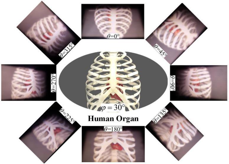
This Comparison Chart illustrates 3D light-field reconstructions of the thoracic cavity for medical diagnosis and education. The central oval image shows a clear, frontal anatomical diagram of the human rib cage and sternum with the heart positioned internally. Surrounding this central figure are eight rectangular frames displaying diagnostic-style 3D renderings of the same structures from different angular perspectives (theta, θ) in 45-degree increments from 0° to 315°. These peripheral images demonstrate the annular viewing capabilities of tabletop light-field displays, showing how the parallax shifts to reveal different facets of the heart and skeletal anatomy. The renderings emphasize depth cues and geometric relationships between the sternum, ribs, and cardiac organ. Some frames exhibit varying levels of clarity, likely to demonstrate the effects of the facet-braiding phenomenon on image quality at specific viewing angles. The content serves as a demonstration of high-fidelity volumetric rendering for biomedical visualization and virtual anatomy training.
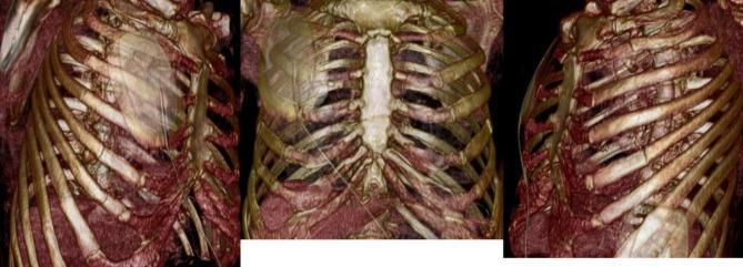
This diagnostic image consists of three panels showing 3D volume-rendered CT reconstructions of a human thoracic cage in various orientations (right oblique, anterior, and left oblique views). The visualization highlights the skeletal anatomy of the ribcage and sternum using a brownish-gold color scale for bone density. Key anatomical features visible include the manubrium and body of the sternum, the costal cartilages, and the curvature of the ribs as they extend from the thoracic spine. In the anterior and oblique views, there is a visible indentation or 'anterior chest window' deformity, suggesting a traumatic flail chest or structural instability of the sternocostal junction. The 3D rendering provides high-resolution detail of the bony integrity and spatial alignment, which is clinically significant for evaluating paradoxical chest wall movement and planning surgical stabilization, such as the Nuss procedure or internal rib fixation. Deep to the ribcage, soft tissue densities of the thoracic cavity are partially visible due to adjusted transparency settings on the CT workstation.
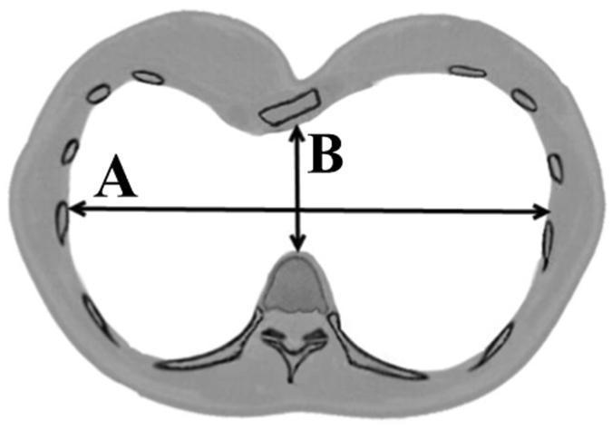
This diagnostic diagram represents an axial (cross-sectional) view of the human thorax, specifically demonstrating the methodology for calculating the Haller index used in evaluating Pectus Excavatum severity. The diagram highlights the skeletal structures of the thoracic cage: the vertebral body is positioned posteriorly, and the sternum is shown anteriorly with a concave depression characteristic of funnel chest. Bilateral ribs define the lateral boundaries of the thoracic cavity. Two primary measurements are labeled: 'A' represents the maximum transverse diameter (laterolateral distance) measured between the inner aspects of the rib cage; 'B' represents the minimum anteroposterior diameter, measured from the posterior surface of the sternal depression to the anterior surface of the vertebral body. The Haller index is mathematically defined as the ratio A/B. This schematic is essential for clinical imaging assessment in thoracic surgery, particularly for pre-operative planning of the Nuss procedure, providing a quantitative measure of chest wall deformity.
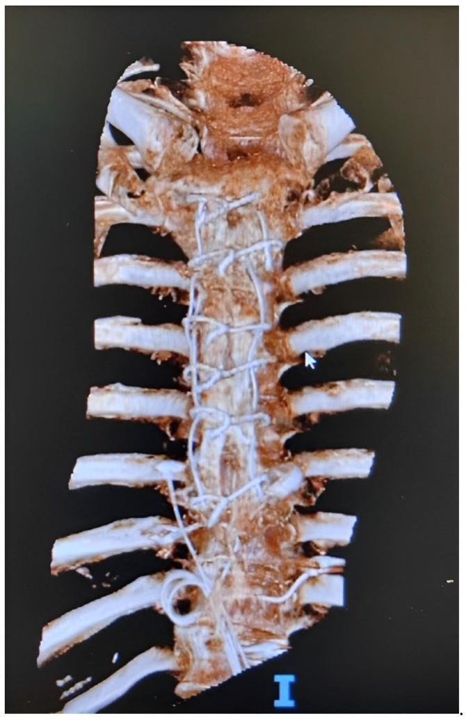
This 3D volume-rendered CT reconstruction displays the anterior thoracic cage, focusing on the sternum and costal cartilages. The primary finding is the presence of multiple radiopaque surgical wires (sternal cerclage) distributed along the midline of the sternum, from the manubrium through the body. These findings are characteristic of previous median sternotomy closure. The reconstruction clearly delineates the bony anatomy of the ribs articulating with the sternum. The visual evidence of hardware without obvious displacement suggests postoperative stabilization, though the clinical context may involve investigating complications such as sternal dehiscence or osteomyelitis. This diagnostic image is intended for educational use in thoracic surgery and radiology to illustrate surgical synthesis materials and post-sternotomy skeletal anatomy.
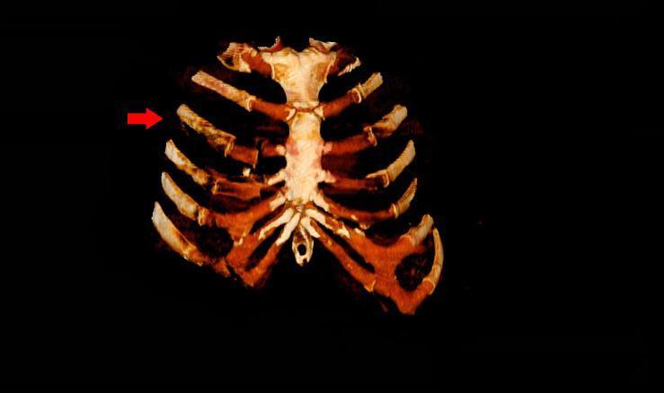
This diagnostic image is a three-dimensional (3D) reconstruction of a chest CT scan, providing a detailed anterior view of the thoracic cage. The image highlights the skeletal anatomy including the sternum and bilateral ribs. A red arrow indicates pathology on the right side of the chest at the level of the third rib. The reconstruction reveals multiple traumatic injuries characterized by costochondral dislocations and fractures. Specifically, there is a visible disruption and misalignment at the costochondral junctions of the right third, fourth, and fifth ribs. These lesions demonstrate a loss of continuity between the osseous portion of the ribs and their corresponding costal cartilages that normally articulate with the sternum. The sternal body remains largely intact, but the significant displacement of the anterior rib segments indicates severe blunt force trauma. This visual serves as an educational tool for identifying chest wall instability and distinguishing costochondral separation from simple rib fractures in a clinical trauma setting.
Anatomy of the Thoracic Cage
1. Overview and Boundaries
| Boundary | Structure |
|---|---|
| Anterior | Sternum and costal cartilages |
| Posterior | Thoracic vertebral column |
| Lateral | Ribs and intercostal spaces |
| Superior aperture (thoracic inlet) | T1, 1st ribs + costal cartilages, manubrium |
| Inferior aperture (thoracic outlet) | T12, 11th & 12th ribs, costal arch, xiphoid |
2. The Sternum
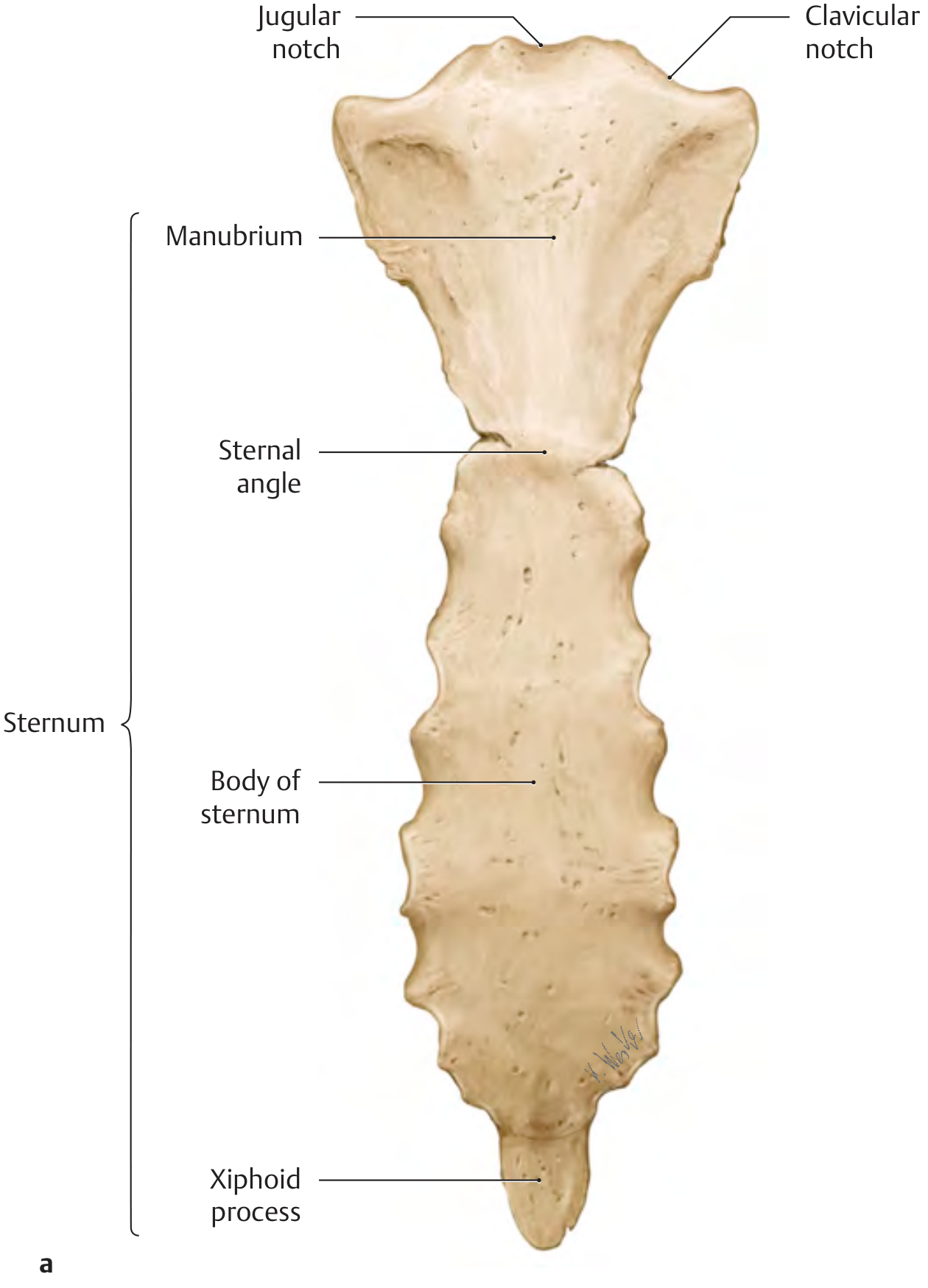
Manubrium
- The broad, superior segment
- Bears the jugular notch (suprasternal notch) at its superior border - a palpable midline depression
- Clavicular notches on each side of the jugular notch for articulation with the medial end of the clavicle (sternoclavicular joints)
- First costal notch just below the clavicular notch - synchondrosis with the 1st costal cartilage
- At its inferior border is a partial facet for the 2nd costal cartilage
Sternal Angle (Angle of Louis)
- The junction between the manubrium and the body
- A palpable transverse ridge where the manubrium is typically angled slightly backward relative to the body
- Marks the level of the 2nd costal cartilage - the most reliable surface landmark for counting ribs
- Also corresponds to the level of the T4/T5 intervertebral disc, the aortic arch, and the bifurcation of the trachea
Body of the Sternum
- The long, narrow middle portion
- Lateral borders bear costal notches for the 3rd through 7th costal cartilages
- The 6th and 7th costal notches lie very close together at the inferior end of the body
Xiphoid Process
- The inferior, smallest segment
- Highly variable in shape; often still cartilaginous in adults and may be bifid or perforated
- Has no costal attachments
- Ossifies and fuses with the sternal body typically in the 4th decade
- Important landmark for CPR hand placement and epigastric region boundaries
Sternal Joints
3. The Ribs
| Type | Ribs | Anterior Attachment |
|---|---|---|
| True ribs (vertebrosternal) | 1-7 | Costal cartilage directly to sternum |
| False ribs (vertebrochondral) | 8-10 | Costal cartilage joins the cartilage above |
| Floating ribs (vertebral) | 11-12 | No anterior attachment |
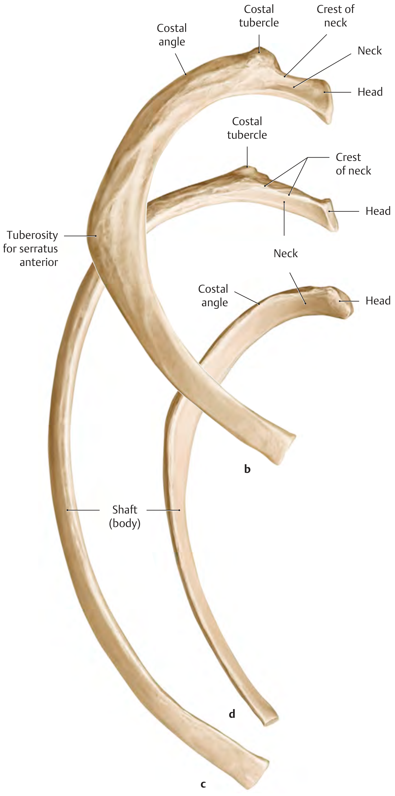
Parts of a Typical Rib (Ribs 3-9)
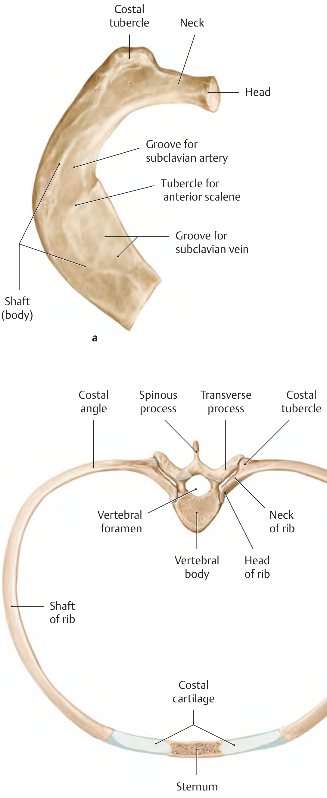
- Head of the rib - has two articular facets (superior and inferior) separated by a crest, for articulation with the bodies of two adjacent vertebrae (the numerically corresponding vertebra and the one above). The crest is connected to the intervertebral disc by the intra-articular ligament.
- Neck of the rib - a flattened bar of bone connecting head to tubercle; bears a sharp superior crest of the neck (except on rib 1)
- Costal tubercle - a rounded prominence at the junction of the neck and shaft; its articular facet articulates with the transverse process of the corresponding vertebra (costotransverse joint)
- Shaft (body) - the long curved portion; curves sharply at the costal angle (where the shaft bends anterolaterally). The shafts of ribs 2-12 are twisted about their long axis so external surfaces face slightly downward at the vertebral end and slightly upward anteriorly
- Costal groove - a groove along the inferior inner border of the shaft (ribs 2-10) protecting the intercostal neurovascular bundle (vein, artery, nerve from superior to inferior within the groove)
Atypical Ribs
- 1st rib: Shortest, broadest, most curved; lies nearly horizontal; has a groove for the subclavian vein anteriorly and a groove for the subclavian artery posteriorly, separated by the scalene tubercle (insertion of anterior scalene). Its head has only a single facet (articulates only with T1). No costal groove.
- 2nd rib: Has a tuberosity for serratus anterior on its outer surface
- 10th rib: Head has a single articular facet only
- 11th and 12th ribs (floating): No neck or tubercle; short, tapering; no costal groove; no anterior articulation
Costal Cartilages
4. Joints of the Thoracic Cage
Sternocostal Joints
- 1st rib: Synchondrosis (no joint cavity) - a primary cartilaginous joint
- 2nd - 5th ribs: True synovial joints with joint cavities, reinforced by radiate sternocostal ligaments that radiate from the perichondrium of the costal cartilage to the anterior sternal surface, blending to form the sternal membrane
- 6th and 7th ribs: Synchondroses
Costovertebral Joints
- Between the two articular facets on the head of the rib and the costal facets on the bodies of two adjacent vertebrae (and the intervertebral disc)
- A synovial joint divided by an intra-articular ligament into two compartments
- Strengthened by the radiate ligament anteriorly
- Between the articular facet of the costal tubercle and the costal facet on the transverse process of the same-numbered vertebra
- Absent in ribs 11 and 12
- Strengthened by three ligaments: costotransverse ligament, superior costotransverse ligament, and lateral costotransverse ligament
Interchondral Joints
5. Intercostal Spaces and the Intercostal Neurovascular Bundle
6. Muscles of the Thoracic Cage
Intercostal Muscles (three layers)
| Muscle | Course | Action | Innervation |
|---|---|---|---|
| External intercostal | Obliquely forward and downward; from costal tubercle to chondro-osseous junction | Elevates ribs (inspiration) | Intercostal nerves T1-T11 |
| Internal intercostal | Obliquely backward and downward; from costal angle to sternum | Depresses ribs (expiration) | Intercostal nerves T1-T11 |
| Innermost intercostal | Same course as internal; separated by the neurovascular bundle | Same as internal intercostals | Intercostal nerves |
Transversus Thoracis
- Origin: Inner surface of the sternum and xiphoid process
- Insertion: Inner surface of the costal cartilages of ribs 2-6
- Action: Lowers the ribs (expiration)
- Innervation: Intercostal nerves 2-7
Subcostal Muscles
- Same orientation as internal intercostals but span across one or two ribs
- Located posteriorly, mainly at the 6th-11th ribs
Scalene Muscles (accessory respiratory muscles)
- Anterior scalene: C3-C6 vertebrae → 1st rib (scalene tubercle)
- Middle scalene: C3-C7 vertebrae → 1st rib (posterior to subclavian groove)
- Posterior scalene: C5-C7 vertebrae → 2nd rib
- Action: With ribs mobile, they elevate the upper ribs in forced inspiration. With ribs fixed, they flex/laterally bend the neck.
Diaphragm
- Costal part: Inner surface of ribs 7-12
- Lumbar part (crura): L1-L3 vertebral bodies and anterior longitudinal ligament
- Sternal part: Posterior surface of the xiphoid
- Insertion: All fibers converge on the central tendon
- Innervation: Phrenic nerve (C3-C5)
- During inspiration, the diaphragm descends 4-6 cm, increasing thoracic volume; during expiration it rises
7. Respiratory Mechanics of the Thoracic Cage
- Upper ribs (1-6): The axis is oriented closer to the coronal plane → rib elevation primarily increases the sagittal (antero-posterior) diameter ("pump-handle" movement)
- Lower ribs (7-10): The axis is oriented closer to the sagittal plane → rib elevation primarily increases the transverse diameter ("bucket-handle" movement)
- Floating ribs (11-12): Act as fulcra for the diaphragm ("caliper" movement)
8. Clinical Landmarks and Surface Anatomy
- Jugular notch: T2/T3 level; inferior margin of the neck
- Sternal angle (angle of Louis): T4/T5 level; 2nd rib; carina; aortic arch
- Xiphisternal junction: T9 level
- Costal margin: Formed by cartilages of ribs 7-10; epigastric angle between left and right margins is typically ~70° in males
- Nipple: Usually at the 4th intercostal space in males; variable in females
- The 2nd rib is typically the most superior palpable rib (1st is hidden under the clavicle)