
Biomechanics of hip 15 marks ms ortho
Reading File
Now let me search the medical library for hip biomechanics content in parallel:
Finding Sources
Finding Sources
Excellent - I found the key sources. Let me read the main hip biomechanics sections from Bailey & Love, Campbell's, and Thieme in parallel:
Reading File
Reading File
Finding Sources
Now let me get more content from Campbell's and Firestein & Kelley for the joint reaction force statics section, plus Miller's Review:
Reading File
Reading File
Finding Sources
Let me get more from Campbell's (continued forces section) and search for additional details on femoral neck angle, Trendelenburg, and gait:
Reading File
Finding Sources
Finding Sources
Reading File
Finding Sources
I now have comprehensive data from multiple authoritative orthopaedics sources. Let me also fetch the key diagrams to include in the answer:
Loading Image
Loading Image
I now have all the material needed for a comprehensive 15-mark MS Ortho answer. Let me compile the full answer:
Biomechanics of the Hip Joint
(MS Orthopaedics - 15 Marks)
1. Introduction
The hip joint is a multi-axial ball-and-socket (spheroidal) synovial joint between the femoral head and the acetabulum. Its biomechanical properties allow it to transmit enormous loads during activities of daily living while permitting a wide range of motion.
2. Geometry and Osseous Architecture
Femoral Neck-Shaft (Neck-Shaft) Angle
- Normal: 125-130° (mean ~130° in men, ~128° in women)
- Coxa vara: angle < 120° - reduces abductor lever arm, Trendelenburg gait
- Coxa valga: angle > 135° - reduces abductor leverage, increases joint contact force
Femoral Neck Anteversion
- The femoral neck subtends an angle of 15-25° anterior to the transcondylar axis (anteversion)
- Increased anteversion: toe-in gait, reduces anterior hip stability
- Decreased anteversion (retroversion): toe-out gait, predisposes to cam-type impingement
Acetabular Geometry
- The acetabulum faces laterally, anteriorly, and inferiorly (~45° inclination, ~15-20° anteversion)
- The lunate articular surface is horseshoe-shaped; the acetabular fossa is filled with fibroadipose tissue
- The labrum deepens the socket, increasing coverage and stability
Trabecular Architecture (Ward's Systems)
Two primary trabecular systems transmit load:
- Medial (compressive) system: arises from the medial cortex/calcar femorale, fans into the femoral head - resists compressive loads
- Lateral (tensile) system: from the lateral cortex to the superior femoral head - resists tensile forces
- The Ward's triangle (between the two systems) is an area of relative weakness - fractures occur here in osteoporosis
- The calcar femorale: a dense vertical plate of cortical bone at the posteromedial femoral neck that provides the principal structural support
3. Range of Motion
The hip has 3 degrees of freedom (3 axes through the femoral head center):
| Plane | Axis | Movements | Normal Range |
|---|---|---|---|
| Sagittal | Transverse | Flexion / Extension | Flexion: 120-135°; Extension: 15-30° |
| Coronal | Sagittal (AP) | Abduction / Adduction | Abduction: 0-40°; Adduction: 0-30° |
| Transverse | Longitudinal | Internal / External rotation | IR: 30-40°; ER: 40-60° |
Functional requirements for ADLs: flexion ≥120°, abduction ≥20°, rotation ≥20°.
Muscles controlling motion:
- Flexors: iliopsoas (primary), rectus femoris, sartorius
- Extensors: gluteus maximus, hamstrings
- Abductors: gluteus medius and minimus (primary stabilizers in stance)
- External rotators: piriformis, obturators, gemelli, quadratus femoris ("POGO-Q")
- Internal rotators: anterior fibers of gluteus medius/minimus, tensor fascia lata
4. Forces Acting on the Hip Joint - The Lever Arm Concept
This is the most testable section for MS Orthopaedics.
The Two-Lever System
The hip in single-limb stance functions as a class 1 lever (fulcrum at the hip joint center):
- Load lever arm (B-X): from the center of the femoral head (B) to the body's center of gravity (X) - approximately 2.5 times longer than the abductor lever arm
- Force (abductor) lever arm (A-B): from the greater trochanter (insertion of abductors, A) to the center of the femoral head (B)
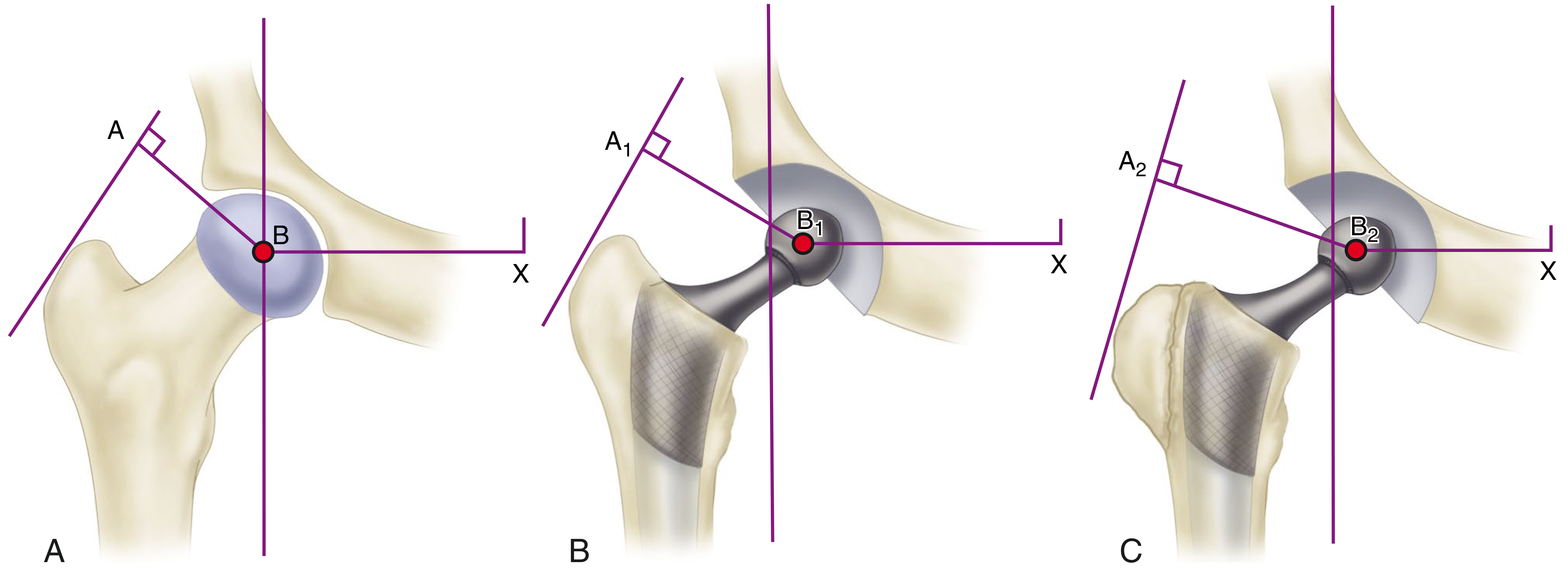
Lever arms acting on the hip joint. A: Normal. B: Medialization of acetabulum shortens body weight lever arm (B1-X). C: Lateral reattachment of greater trochanter lengthens abductor lever arm further.
Mathematical Derivation of Joint Reaction Force (JRF)
For static equilibrium in single-limb stance:
Abductor moment = Body weight momentAbductor Force (AF) × Abductor Lever Arm = Body Weight (BW) × Body Weight Lever ArmAF × d_A = BW × d_BWSince d_BW / d_A ≈ 2.5:1AF ≈ 2.5 × BW
The Joint Reaction Force (JRF) = Sum of Abductor Force + Body Weight component
JRF = AF + BW ≈ 2.5 BW + BW ≈ 3.5 × BW (in single-limb stance)
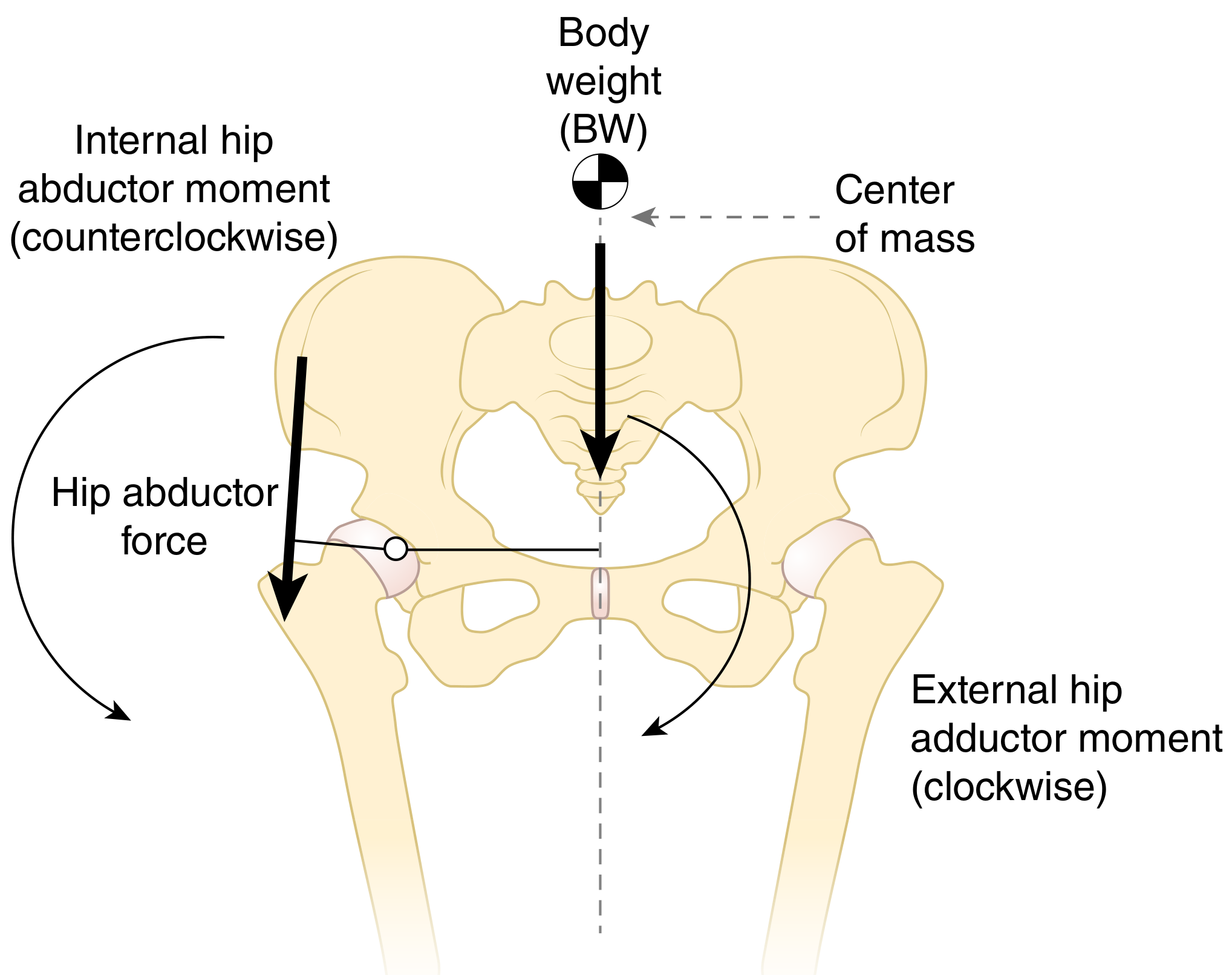
The ground reaction force passes medial to the hip joint, creating an external adduction moment (clockwise). The hip abductors generate an internal abduction moment (counterclockwise) to maintain pelvic equilibrium.
5. Joint Reaction Forces - Summary Table
| Activity | JRF (× Body Weight) |
|---|---|
| Lying flat in bed | Body weight itself |
| Lifting the leg from bed (straight leg raise) | ~1.5 × BW |
| Walking (stance phase) | ~3.0-3.5 × BW |
| Calculated peak during gait (analytical models) | 3.5-5.0 × BW |
| Single-limb stance | ~3 × BW |
| Experimentally measured (instrumented prostheses) | 2.6-3.0 × BW |
| Running and jumping | up to 10 × BW |
| Arthritic hip (lever arm ratio 4:1) | Higher; surgery can reduce by 30% |
- Bailey & Love's Surgery, 28th Ed. + Campbell's Operative Orthopaedics, 15th Ed., 2026
6. Trendelenburg Sign and Gait
During normal single-limb stance, the ipsilateral abductors (gluteus medius/minimus) contract to maintain the contralateral pelvis level.
Trendelenburg sign is positive when the pelvis drops on the unsupported (contralateral) side, indicating:
- Weakness or paralysis of ipsilateral abductors (gluteus medius)
- Shortened abductor lever arm (e.g., coxa valga, unreduced hip dislocation, THA malposition)
- Superior gluteal nerve palsy
- Painful hip (antalgic pseudo-Trendelenburg)
Trendelenburg gait (abductor lurch): The patient lurches toward the weak side (ipsilateral trunk lean) to shift the body's center of gravity over the stance leg, reducing the moment arm of body weight and decreasing the required abductor force.
In coxa valga, the moment arm for abductors is smaller - greater abductor force is required to generate the same moment - leading to higher JRF.
7. Clinical Application - Surgical Manipulation of Biomechanics
Charnley's Low-Friction Arthroplasty Concept
Based on biomechanical principles to reduce joint forces:
- Medialization of the acetabulum: deepens the cup medially, shortening the body weight lever arm (B-X → B1-X), reducing required abductor force
- High-offset femoral stem: lateralizes the greater trochanter, lengthening abductor lever arm (A-B → A1-B1)
- Lateral + distal reattachment of greater trochanter: further lengthens abductor lever arm (A2-B2), tightens abductors
Result: Ratio approaches 1:1, theoretically reducing total hip load by ~30%.
Hip Offset (Femoral Offset)
- Defined as the perpendicular distance from the femoral shaft axis to the center of the femoral head
- Restoring normal offset is critical in THA:
- Reduced offset: weakens abductor complex, increases JRF, causes Trendelenburg gait, increases polyethylene wear risk
- Increased offset: improves abductor tension and lever arm, but may increase torsional stresses on stem
Forces in Different Planes
- Coronal plane: medial deflection of the stem
- Sagittal plane: posterior deflection (especially with hip flexion - rising from a chair, ascending stairs)
- Combined: produces torsion of the femoral stem - critical for implant design
8. Stability Mechanisms
The hip is inherently stable due to:
- Bony congruence: deep socket, femoral head coverage by acetabulum (~270°)
- Labrum: creates a suction effect, deepens socket, increases stability by ~10%
- Capsular ligaments (static stabilizers):
- Iliofemoral (Y-ligament of Bigelow): strongest ligament in the body; limits extension and external rotation
- Pubofemoral ligament: limits abduction and extension
- Ischiofemoral ligament: limits internal rotation in extension
- Negative intra-articular pressure: suction mechanism resists distraction
- Ligamentum teres: minor role in adults; transmits the medial circumflex artery branch in children
- Periarticular muscles: primary dynamic stabilizers
9. Biomechanics in Gait
During the stance phase, the hip joint:
- Absorbs ground reaction forces (3-5 × BW peak)
- Requires adequate abductor function to maintain pelvic stability
- Normal hip extension (10-15°) in late stance propels the body forward
During the swing phase:
- Hip flexes to ~30-40° (minimum needed for foot clearance)
- Iliopsoas is the primary swing initiator
- Losing hip extension in stance increases pelvic anterior tilt and compensatory lumbar lordosis
Cadence, stride length, and energy efficiency are all affected by altered hip biomechanics (e.g., shortening of the limb, joint stiffness, abductor weakness).
10. Patho-Biomechanics - Clinical Correlates
| Deformity / Condition | Biomechanical Consequence |
|---|---|
| Coxa vara | Shortens abductor lever arm; Trendelenburg gait; reduces JRF |
| Coxa valga | Lengthens abductor lever arm; increases JRF; associated with dysplasia |
| Hip dysplasia | Reduced acetabular coverage → increased contact stress → labral tears and OA |
| Femoral neck fracture risk | Increased hip axis length, lower NSA, osteoporosis (loss of trabecular bone in Ward's triangle) |
| SCFE (Slipped Capital Femoral Epiphysis) | Alters biomechanics; ideal treatment restores mechanics and stimulates physeal closure |
| Chiari osteotomy | Medializes hip, improves abductor mechanics, often corrects Trendelenburg limp |
Summary Points (for Quick Recall)
- JRF = Body weight component + Abductor force component
- Abductor lever arm ≈ 1/2.5 of body weight lever arm in normal hip
- 3× BW during walking; 10× BW during running/jumping
- Positive Trendelenburg = inadequate ipsilateral abductors
- Hip stability: bony congruence + Y-ligament of Bigelow + capsule + negative intra-articular pressure
- Key NSA: 125-130° normal; anteversion 15-25° normal
- Surgical strategies to reduce JRF: medialization of cup + restoration of offset
Sources: Campbell's Operative Orthopaedics 15th Ed. 2026; Bailey & Love's Short Practice of Surgery 28th Ed.; Rockwood & Green's Fractures in Adults 10th Ed. 2025; Firestein & Kelley's Textbook of Rheumatology; THIEME Atlas of Anatomy: General Anatomy and Musculoskeletal System
Diagrams
Let me pull all the relevant diagrams from the textbooks for hip biomechanics.
Finding Sources
Finding Sources
Reading File
Reading File
Reading File
Now let me read more of the THIEME atlas section to get all the image URLs, and also get the trabecular/Trendelenburg/torsion diagrams:
Reading File
Reading File
Finding Sources
I found the coxa vara/valga/normal load diagram. Let me get all the image URLs from that section and the trabecular section:
Reading File
Reading File
Finding Sources
Reading File
Reading File
Reading File
I now have all the image URLs. Let me fetch all the key diagrams in parallel:
Loading Image
Loading Image
Loading Image
Loading Image
Loading Image
Loading Image
Loading Image
Loading Image
Loading Image
Loading Image
Here are all the key diagrams for hip biomechanics, organized by topic:
Hip Biomechanics - All Diagrams
Diagram 1 - Three Axes of Motion at the Hip Joint
(THIEME Atlas of Anatomy - Musculoskeletal System)
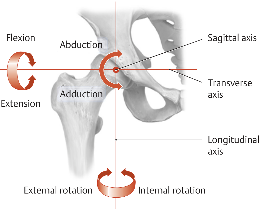
Key points: All three axes pass through the center of the femoral head.
- Transverse axis → Flexion / Extension
- Sagittal (AP) axis → Abduction / Adduction
- Longitudinal axis → Internal / External Rotation
Diagram 2 - Range of Motion: Flexion / Extension
(THIEME Atlas of Anatomy)
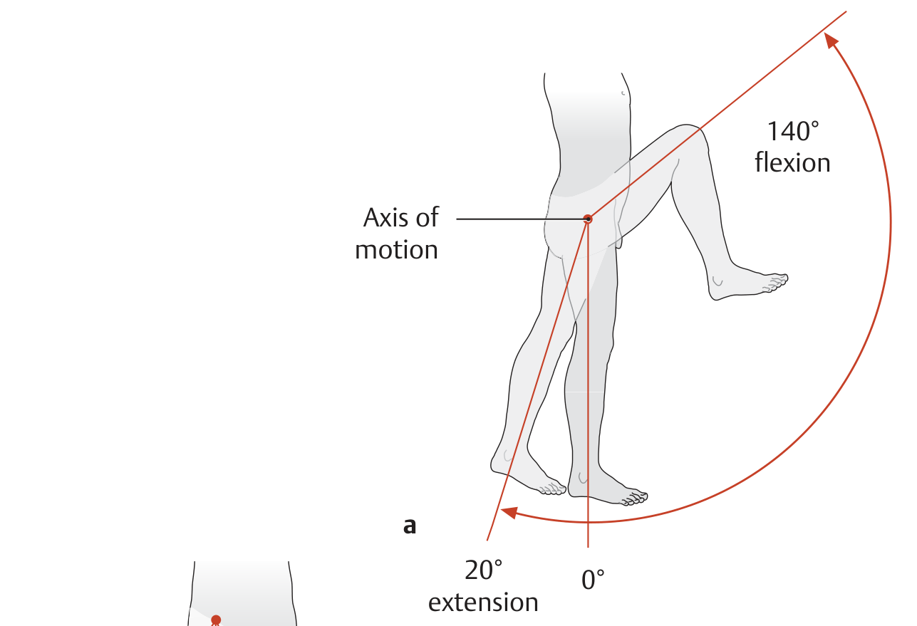
Normal values: Flexion 0-140°, Extension 0-20°
Diagram 3 - Range of Motion: Abduction / Adduction
(THIEME Atlas of Anatomy)
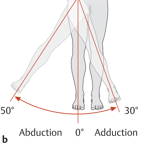
Normal values: Abduction 0-50°, Adduction 0-30°
Diagram 4 - Range of Motion: Internal / External Rotation (hip flexed 90°)
(THIEME Atlas of Anatomy)
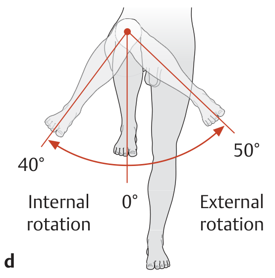
Normal values: Internal rotation 0-40°, External rotation 0-50°
Diagram 5 - Lever Arms Acting on the Hip (THA Biomechanics)
(Campbell's Operative Orthopaedics 15th Ed. 2026)
Caption: A = Normal hip. B-X = Body weight lever arm; A-B = Abductor lever arm (shorter).
- B: Medialization of acetabulum shortens the body weight lever arm (B1-X); high-offset neck lengthens abductor lever arm (A1-B1)
- C: Lateral + distal reattachment of greater trochanter lengthens abductor lever arm further (A2-B2)
Diagram 6 - Hip Abductor Force: Maintaining Level Pelvis in Single-Limb Stance
(Firestein & Kelley's Textbook of Rheumatology)
Key point: Ground reaction force passes medial to the hip joint → external hip adduction moment (clockwise). Hip abductors generate internal abduction moment (counterclockwise) to maintain level pelvis.
Diagram 7 - Hip Joint Load vs Neck-Shaft Angle: Normal, Coxa Valga, Coxa Vara
(THIEME Atlas of Anatomy)
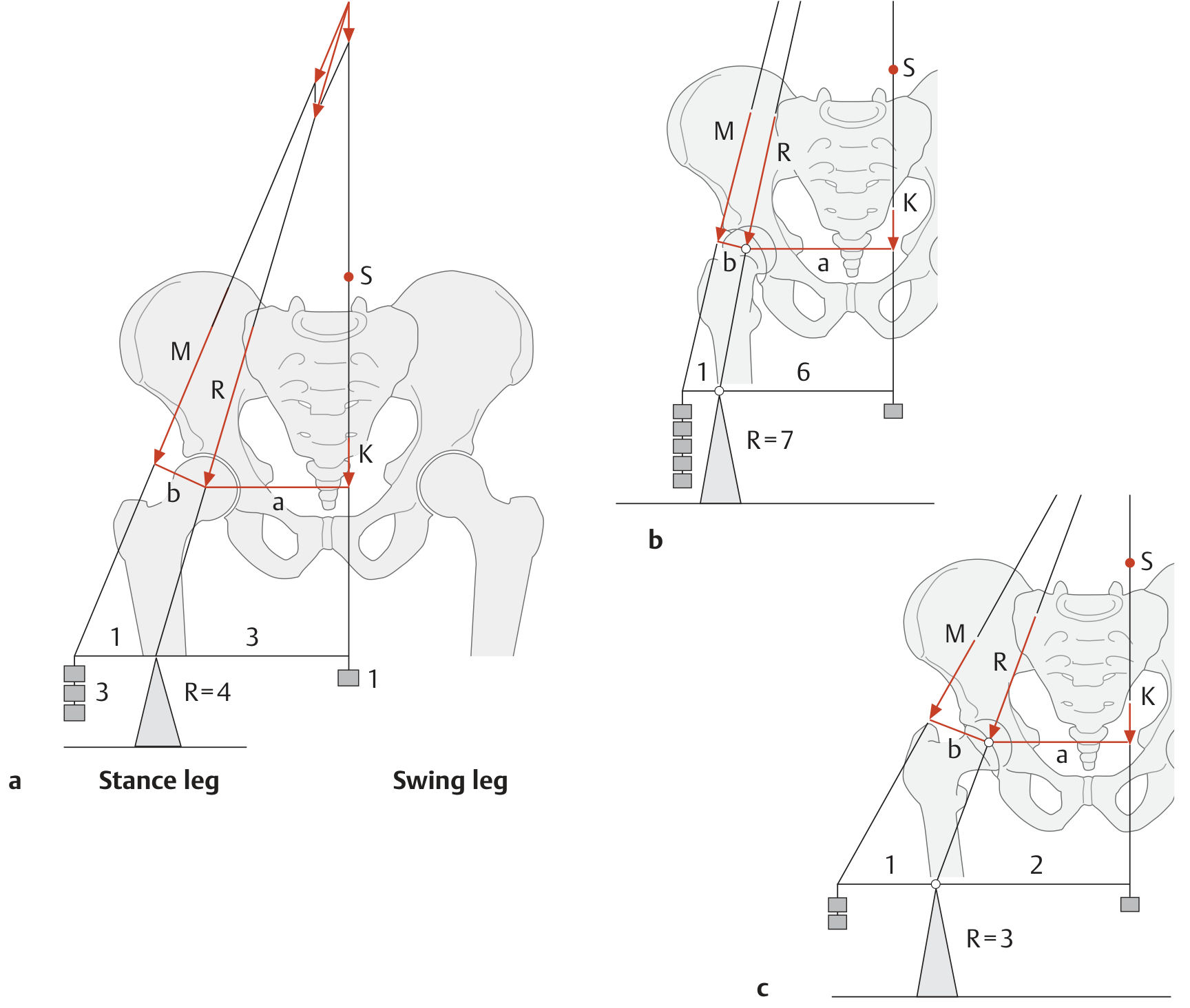
This is the most important biomechanics diagram for the exam:
- Normal CCD angle (~126°): Body weight lever arm (a) ≈ 3× muscle lever arm (b) → R = 4× body weight
- Coxa valga (increased CCD): Muscle lever arm (b) decreases → muscle must work harder → R = 7× body weight
- Coxa vara (decreased CCD): Muscle lever arm (b) increases → less muscle force needed → R = 3× body weight
(M = muscle force, K = partial body weight, R = resultant joint reaction force, S = partial body center of gravity)
Diagram 8 - Reducing Hip Load: Carrying Weight on Affected Side (Duchenne Limp Mechanism)
(THIEME Atlas of Anatomy)
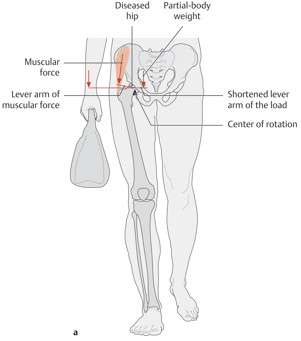
Carrying a bag on the affected (diseased) side shifts the center of gravity toward that side → shortens the load lever arm → reduces joint reaction force → less pain.
Diagram 9 - Reducing Hip Load: Walking Stick on Unaffected Side
(THIEME Atlas of Anatomy)
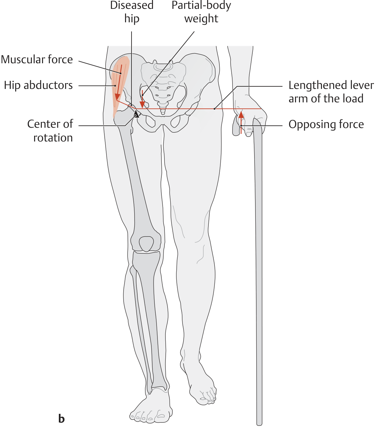
A walking stick held in the contralateral (unaffected) hand provides an opposing force at the end of the load lever arm → reduces the net torque → reduces the required abductor force → reduces JRF. This is the standard advice for hip OA patients.
Diagram 10 - Trendelenburg Gait: Normal vs Positive Trendelenburg vs Trendelenburg Lurch
(Firestein & Kelley's Textbook of Rheumatology)
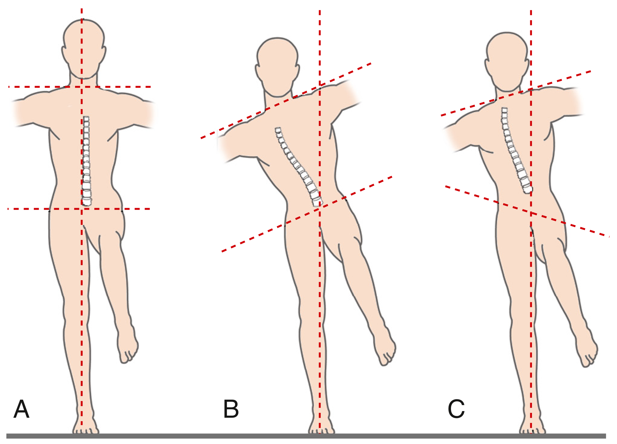
- A - Normal: shoulders and pelvis level in single-limb stance
- B - Positive Trendelenburg lurch + negative Trendelenburg sign: trunk leans over the affected (stance) hip; pelvis remains level because the lean brings center of gravity over the stance leg
- C - Positive Trendelenburg lurch + positive Trendelenburg sign: pelvic obliquity present (contralateral pelvis drops); trunk leaning over involved hip
Diagram 11 - Trabecular Pattern of the Proximal Femur (Ward's Triangle)
(Imaging Anatomy - Bones, Joints, Vessels and Nerves)
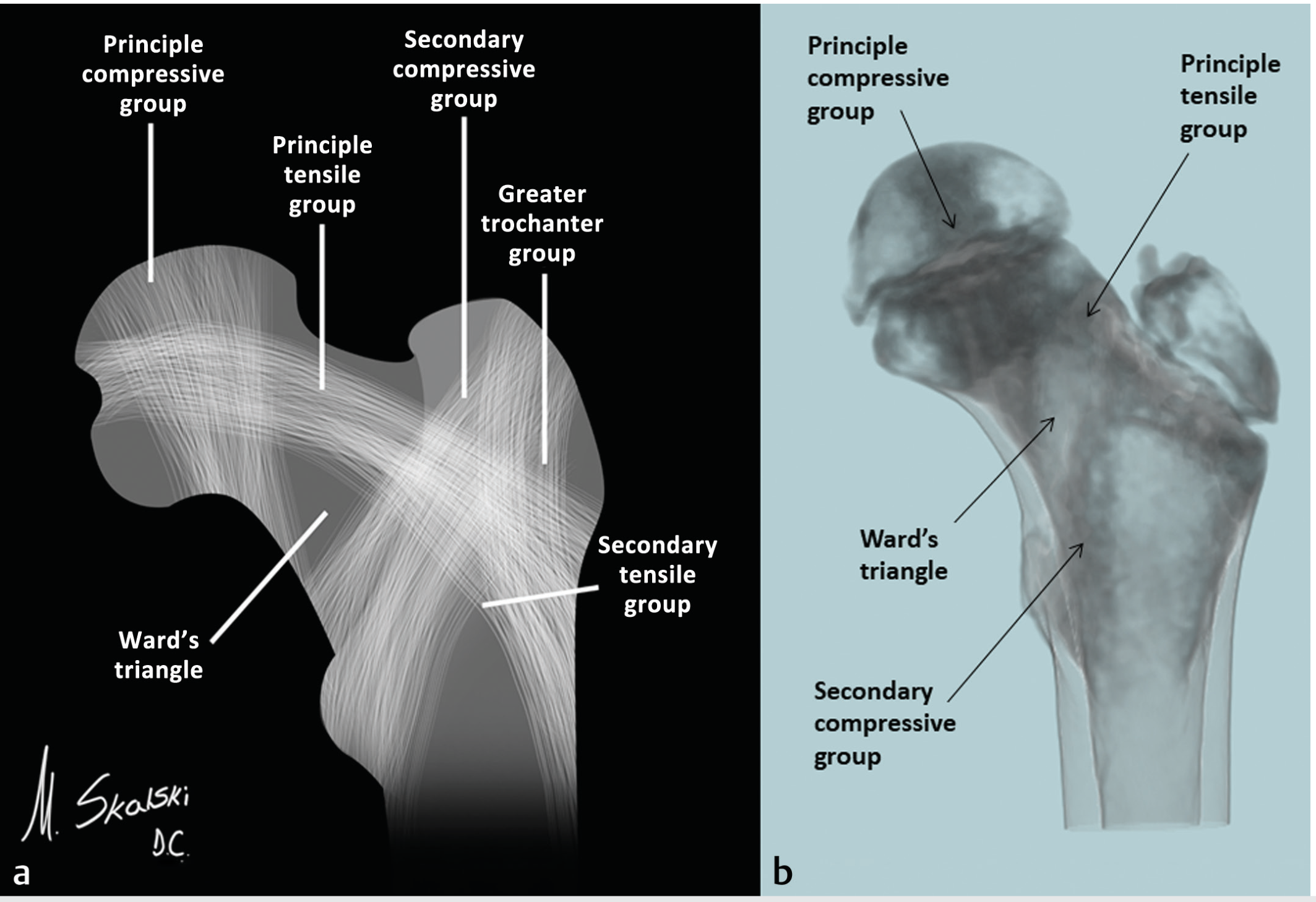
Four trabecular groups:
- Principal compressive group: medial cortex → femoral head (resists compressive loads)
- Principal tensile group: lateral cortex → superior femoral head (resists tensile forces)
- Secondary compressive group: intertrochanteric region, perpendicular to neck
- Secondary tensile group + Greater trochanter group
- Ward's triangle: area of paucity between groups in inferomedial femoral neck → weakest zone, first to lose trabeculae in osteoporosis
Diagram 12 - Forces Producing Torsion of Femoral Stem (THA)
(Campbell's Operative Orthopaedics 15th Ed. 2026)
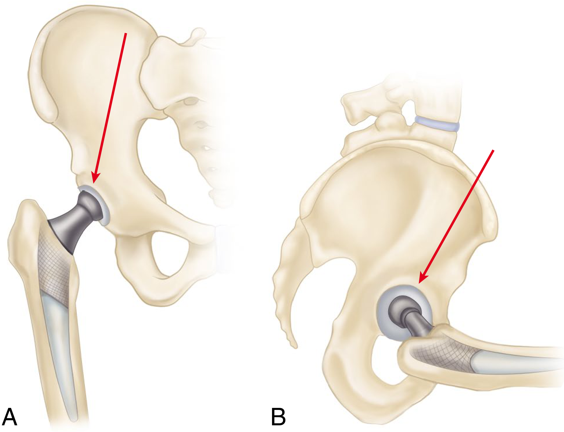
- A (coronal plane): forces tend to deflect the femoral stem medially
- B (sagittal plane): forces (especially with hip flexed - rising from chair, climbing stairs) tend to deflect the stem posteriorly
- Combined effect: produces torsion of the femoral stem - critical design consideration for implants
Summary of diagrams provided:
| # | Topic | Source |
|---|---|---|
| 1 | 3 axes of motion | THIEME Atlas |
| 2 | ROM - Flexion/Extension | THIEME Atlas |
| 3 | ROM - Abduction/Adduction | THIEME Atlas |
| 4 | ROM - Rotation | THIEME Atlas |
| 5 | Lever arms (normal + THA) | Campbell's |
| 6 | Abductor moment / pelvic equilibrium | Firestein & Kelley |
| 7 | JRF vs neck-shaft angle (coxa vara/valga) | THIEME Atlas |
| 8 | Reducing load: bag on affected side | THIEME Atlas |
| 9 | Reducing load: walking stick | THIEME Atlas |
| 10 | Trendelenburg sign/lurch | Firestein & Kelley |
| 11 | Trabecular pattern + Ward's triangle | Imaging Anatomy |
| 12 | Torsion forces on femoral stem | Campbell's |
This is a shared conversation. Sign in to Orris to start your own chat.