
Femur explain with figure
femur bone anatomy diagram labeled anterior posterior
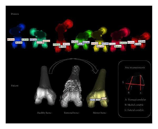
Educational diagram illustrating the preoperative planning for bone allograft selection using 3D modeling and morphometric matching. The top panel shows a donor bank of 3D-segmented distal femur models, each color-coded and annotated with specific anatomical measurements. The bottom panel displays three patient-specific distal femur models: 'Healthy bone' (contralateral side), 'Tumoral bone' showing pathological cortical irregularities and osteoblastic/osteolytic changes, and a 'Mirror bone' generated by reflecting the healthy side to simulate the original anatomy. A separate 'Size measurements' legend defines the three primary landmarks for matching: (A) Transepicondylar width, (B) Medial condyle anterior-posterior diameter, and (C) Lateral condyle anterior-posterior diameter. This visual summarizes the digital workflow for oncological orthopedic surgery, emphasizing the use of 3D registration and segmentation to achieve anatomical congruency between donor tissue and the host site.
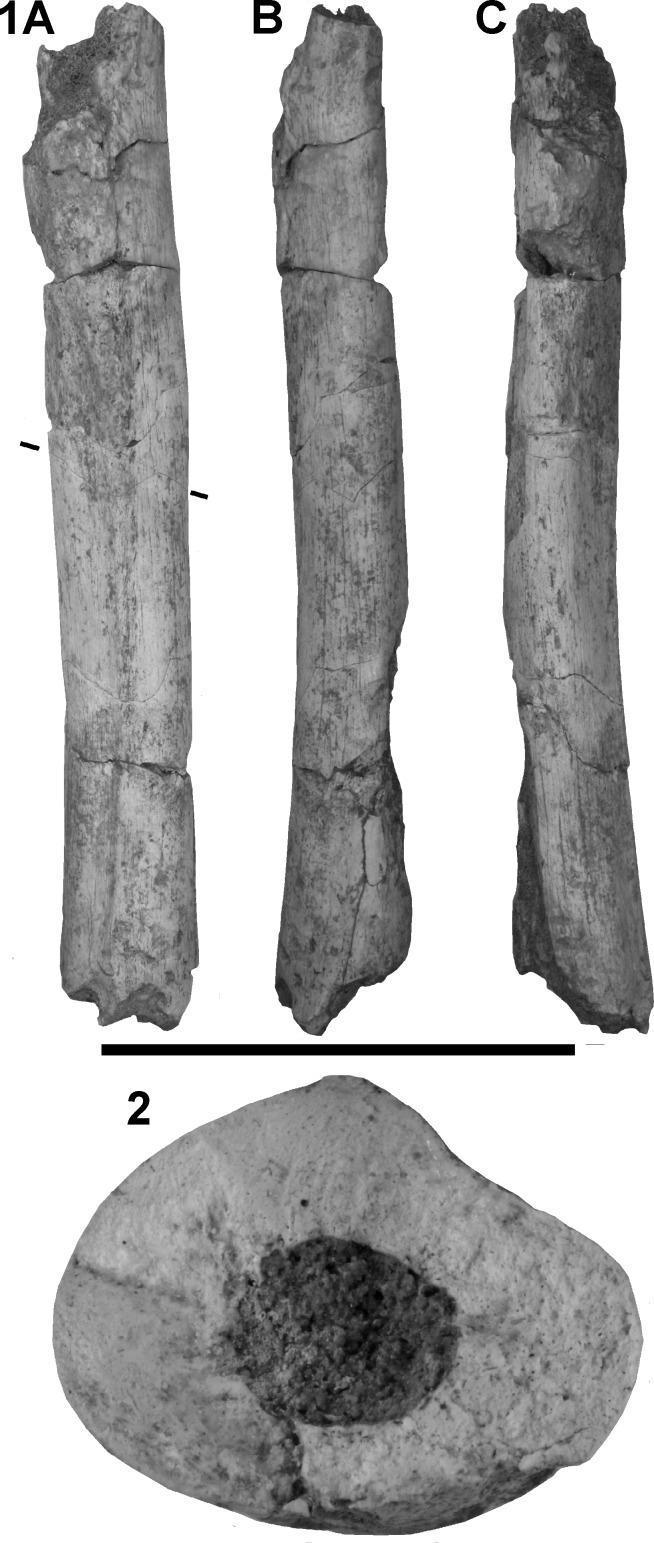
A clinical photograph of a human bone specimen representing the femoral diaphysis of a left femur. The visual content is organized into multiple views: labeled 1A (posterior), 1B (medial), and 1C (lateral) showing the longitudinal shaft, and label 2 showing a transverse cross-section. The bone fragment is approximately 218 mm in length and appears off-white to grey, with visible reconstruction seams and irregular transverse breaks at both the proximal and distal ends. The cortical surface is generally well-preserved on the posterior and medial aspects, though some anterior cortical bone is missing. Image 2 demonstrates the internal anatomy through a cross-sectional view, highlighting a markedly thick and dense cortical bone layer surrounding a central medullary cavity filled with dark granular material. The cross-section reveals an oval morphology with significant mediolateral expansion and a lack of a distinct pilaster. Clinical and educational significance includes the demonstration of paleoanthropological bone morphology, cortical thickness variations, and perimortem or post-mortem surface modifications such as carnivore tooth-marks (pits and notches) located at the extremities.
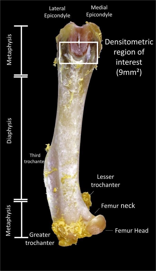
This clinical photograph displays a labeled anterior view of a femur bone, highlighting anatomical landmarks and research parameters for densitometric analysis. The image is divided into three main longitudinal segments: the proximal metaphysis, the central diaphysis (shaft), and the distal metaphysis. Key anatomical landmarks identified with text labels include the femur head, femur neck, greater trochanter, lesser trochanter, and third trochanter at the proximal end, as well as the lateral and medial epicondyles at the distal end. A white rectangular box outlines the 'Densitometric region of interest (9mm²)' located within the distal metaphysis, specifically positioned between the epicondyles on the femoral condyles. The bone surface shows visible remnants of fibrous connective tissue. This anatomical diagram serves as a reference for standardize bone mineral density measurements in experimental osteopenia studies, illustrating the precise location where densitometry data is collected to evaluate bone quality and the effects of pharmaceutical interventions like doxycycline.
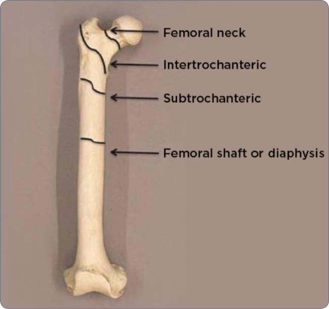
An anatomical diagram of a human femur bone, presented on a neutral background to illustrate common fracture sites and regional anatomy. The image identifies four primary proximal and mid-shaft regions using black labels and arrows. Starting from the proximal end, the 'Femoral neck' is indicated between the femoral head and the trochanters. Immediately distal to this is the 'Intertrochanteric' region, spanning the space between the greater and lesser trochanters. Below this lies the 'Subtrochanteric' region, representing the transition into the main body of the bone. Finally, the long, central portion is labeled as the 'Femoral shaft or diaphysis'. This illustration serves as an educational tool for medical professionals to classify orthopedic injuries, such as hip fractures or atypical femoral fractures (AFF), by precisely defining anatomical zones. The diagram emphasizes the proximal femur’s morphology, including the head, neck, and trochanteric areas, which are critical in radiology and surgical planning.
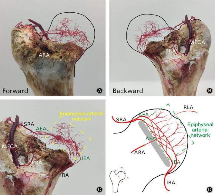
This composite educational resource comprises four panels (A-D) illustrating the complex intraosseous arterial anatomy of the femoral head using a combination of vascular casting and schematic diagrams. Panels A, B, and C present physical macerated bone specimens featuring a red epoxy resin vascular cast of the arterial supply. Panel A (Forward) and B (Backward) show the three-dimensional distribution of the retinacular arteries and the Medial Femoral Circumflex Artery (MFCA). Panel C provides a labeled close-up of the vascular cast, identifying the Superior (SRA), Inferior (IRA), Anterior (ARA), and Posterior (PRA) Retinacular Arteries, as well as the Anterior (AEA) and Inferior (IEA) Epiphyseal Arteries. These vessels converge to form a dense, interconnected 'Epiphyseal arterial network' within the apex of the femoral head. Panel D is a corresponding schematic diagram that maps these vessels and their anastomotic connections, including the Round Ligament Artery (RLA). This content is designed to illustrate the collateral circulation and vascular zones of the proximal femur, critical for understanding the pathophysiology of femoral neck fractures and avascular necrosis (AVN).
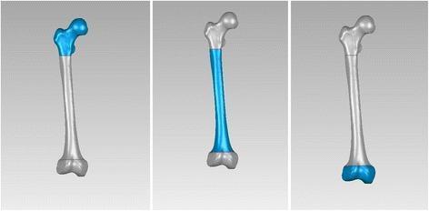
Anatomical diagram consisting of three three-dimensional digital femoral models illustrating the segmentation of the femur for biomechanical or orthopedic analysis. The models are shown in a posterior view, each highlighting a specific anatomical region in blue. The first model (left) highlights the proximal end, including the femoral head, neck, and the greater and lesser trochanteric regions. The second model (center) highlights the diaphysis (shaft), showing the long, slightly curved cortical bone section between the trochanters and the supracondylar flare. The third model (right) highlights the distal end, comprising the medial and lateral condyles and the intercondylar notch. These computer-generated models facilitate the study of intramedullary nail insertion paths, curvature radius, and anatomical fit for orthopedic implants. The visualization serves an educational purpose in musculoskeletal anatomy, orthopedic surgery planning, and biomedical engineering.
femur anatomy proximal distal shaft labeled head neck trochanter condyle
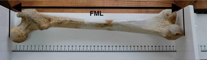
This clinical photograph displays a dry specimen of a right human femur positioned for osteometric analysis. The bone is oriented horizontally on a white osteometric board with its anterior surface facing downward. The proximal end, including the femoral head and greater trochanter, is aligned to the left, while the distal end, showcasing the medial and lateral femoral condyles, is to the right. A double-headed arrow labeled 'FML' (Femur Maximum Length) indicates the measurement span between the most proximal point of the femoral head and the most distal point of the medial femoral condyle. The apparatus includes a linear metric scale for precise quantification. The specimen exhibits natural beige coloration with varying textures: a smooth diaphysis (shaft) and porous, trabecular-rich regions at the epiphyses (ends). This image illustrates standard anthropological and forensic techniques for skeletal measurement, used in stature estimation and morphological study within the fields of anatomy and forensic medicine.
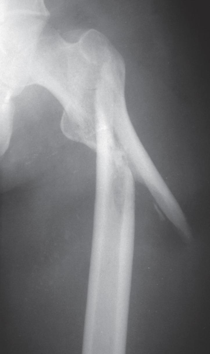
Anteroposterior (AP) radiograph of the proximal femur showing a complex subtrochanteric fracture. The fracture is located distal to the lesser trochanter and exhibits a comminuted or spiral pattern with significant displacement and angulation. A large, sharp cortical spike is visible extending laterally from the proximal fragment. The distal femoral shaft is displaced laterally and superiorly relative to the proximal fragment. Notable for educational purposes is the absence of bridging callus formation three months post-injury, despite the rounding of fracture edges, which indicates a delayed union or non-union. The image demonstrates the limitations of prolonged skeletal traction in achieving anatomical reduction for subtrochanteric femoral fractures. The anatomy shown includes the femoral head, neck, greater trochanter, and the proximal femoral diaphysis.
An anatomical diagram of a human femur bone, presented on a neutral background to illustrate common fracture sites and regional anatomy. The image identifies four primary proximal and mid-shaft regions using black labels and arrows. Starting from the proximal end, the 'Femoral neck' is indicated between the femoral head and the trochanters. Immediately distal to this is the 'Intertrochanteric' region, spanning the space between the greater and lesser trochanters. Below this lies the 'Subtrochanteric' region, representing the transition into the main body of the bone. Finally, the long, central portion is labeled as the 'Femoral shaft or diaphysis'. This illustration serves as an educational tool for medical professionals to classify orthopedic injuries, such as hip fractures or atypical femoral fractures (AFF), by precisely defining anatomical zones. The diagram emphasizes the proximal femur’s morphology, including the head, neck, and trochanteric areas, which are critical in radiology and surgical planning.
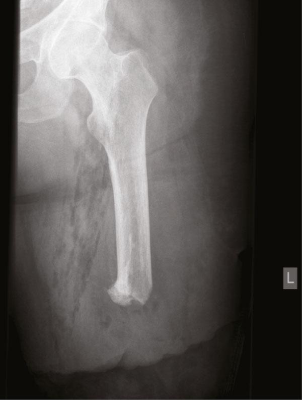
This diagnostic image is a plain radiograph (X-ray) of the left upper leg following an above-knee amputation and subsequent surgical revision. The roentgenogram displays a significantly shortened femur. The proximal anatomy, including the femoral head, neck, and greater trochanter, remains intact within the acetabulum. The distal femoral stump is truncated and demonstrates an irregular, blunted morphology consistent with surgical bone resection and curettage. Notable findings include a decrease in bone density at the distal aspect of the stump, indicating a more porous or osteopenic appearance compared to the mid-shaft. The surrounding soft tissue shows mottled radiographic densities and faint silhouettes, suggestive of post-surgical changes, scarring, and edema within the residual limb. This image is clinically relevant for evaluating stump morphology, bone remodeling, and the presence of heterotopic ossification or surgical complications like gossypiboma-related changes in orthopedics and rehabilitation medicine. A radio-opaque marker 'L' indicates the left orientation.
The Femur - Complete Anatomy
Figures
Parts of the Femur
1. Proximal End
| Structure | Details |
|---|---|
| Femoral Head | Spherical, ~2/3 of a sphere; covered by articular cartilage (except at fovea capitis). Articulates with the acetabulum. |
| Fovea Capitis | Central depression on the head; attachment of the ligamentum teres (carries foveal artery, important in children) |
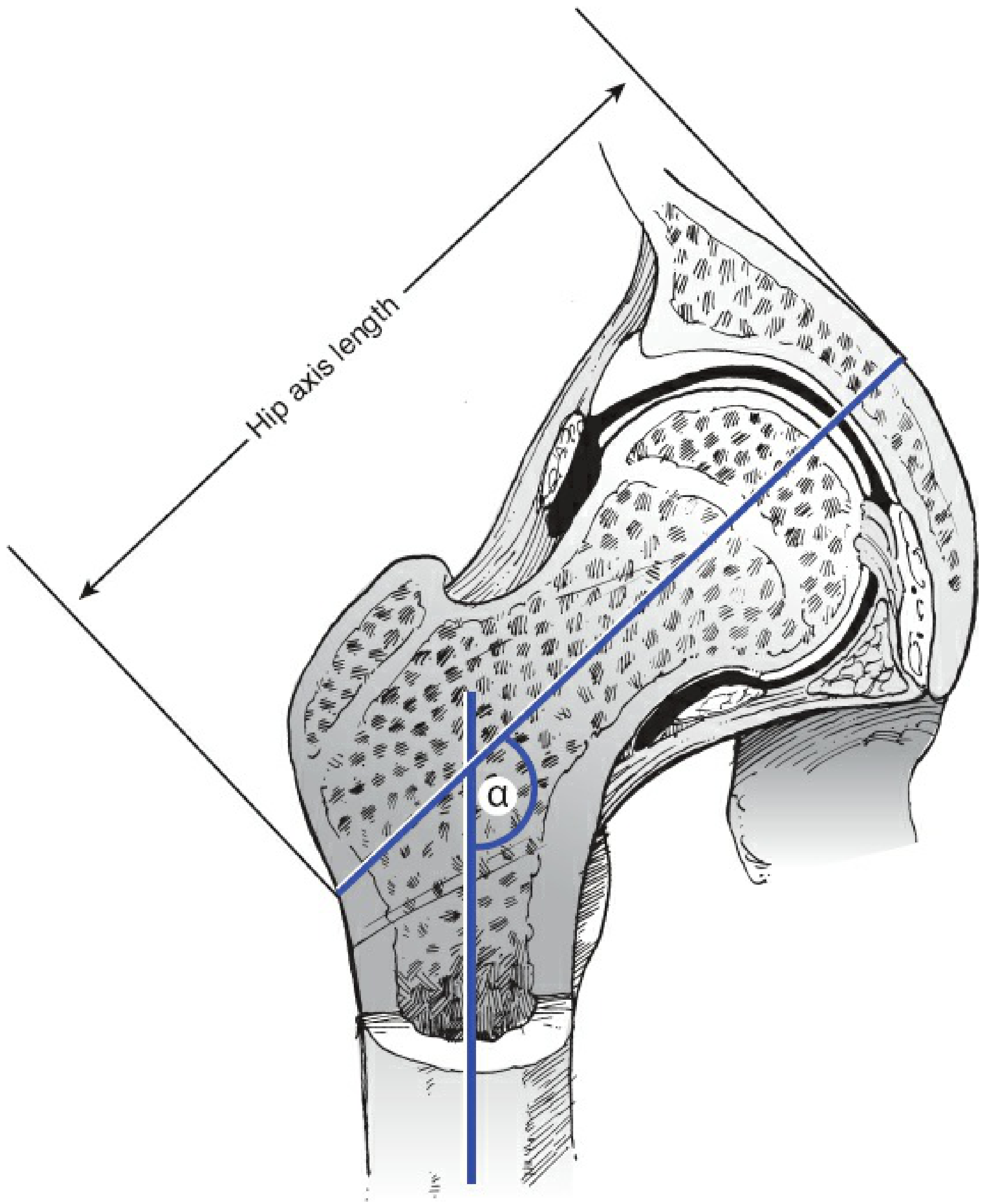
| Femoral Neck | Connects head to shaft. Neck-shaft angle: 125-140° (normal). Anteversion: 15-25° forward of transcondylar axis |
| Greater Trochanter | Large bony prominence projecting laterally and superiorly. Insertion of gluteal abductors (gluteus medius, minimus) |
| Lesser Trochanter | Smaller, posteromedial projection. Insertion of iliopsoas (primary hip flexor) |
| Intertrochanteric Line | Anterior ridge connecting the two trochanters; anterior capsular attachment |
| Intertrochanteric Crest | Posterior ridge with a rounded quadrate tubercle; stronger than the anterior line |
| Calcar Femorale | Dense vertical plate of bone extending from the posteromedial shaft under the lesser trochanter, radiating to the greater trochanter - reinforces the posteroinferior femoral neck |
The center of the femoral head lies at approximately the level of the tip of the greater trochanter in most hips. - Rheumatology (Elsevier, 2022)
2. Shaft (Diaphysis)
- Slightly bowed anteriorly (convex forward)
- Roughly cylindrical but triangular in cross-section
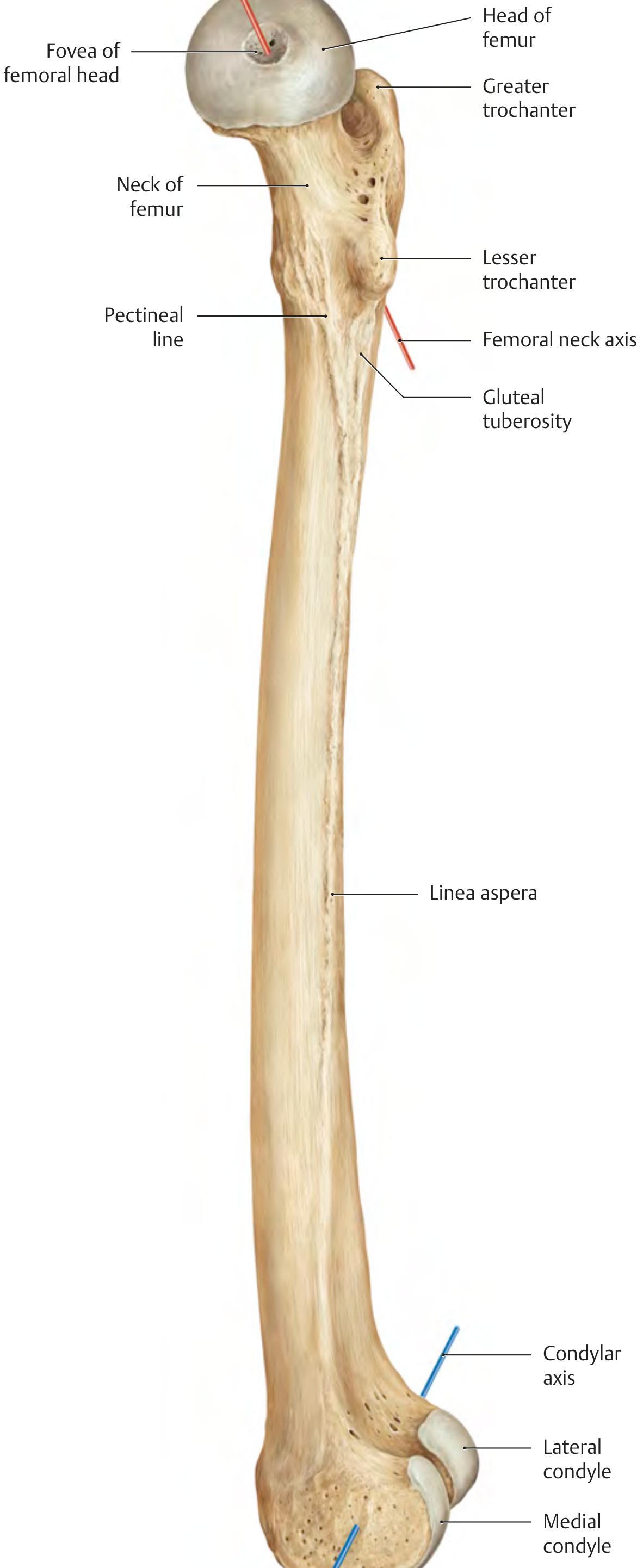
- Linea aspera - prominent posterior longitudinal ridge; gives attachment to multiple muscles (vastus medialis, lateralis, adductors, biceps femoris short head)
- Pectineal line - spiral from lesser trochanter to linea aspera (pectineus insertion)
- Gluteal tuberosity - superolateral extension of linea aspera (gluteus maximus insertion)
- Nutrient foramen - on the posterior shaft, directed proximally
- Subtrochanteric region - the zone just distal to the lesser trochanter, within the proximal 5 cm of the shaft
3. Distal End
| Structure | Details |
|---|---|
| Medial Condyle | Projects more distally; articulates with medial tibial plateau |
| Lateral Condyle | More anterior prominence; articulates with lateral tibial plateau |
| Intercondylar Notch (Fossa) | Deep groove between the condyles posteriorly; lodges the cruciate ligaments |
| Medial Epicondyle | Bony prominence above medial condyle; attachment of medial collateral ligament (MCL) |
| Lateral Epicondyle | Above lateral condyle; attachment of lateral collateral ligament (LCL) |
| Adductor Tubercle | Small projection on the medial epicondyle; insertion of adductor magnus |
| Patellar Surface (Trochlea) | Anterior groove between condyles; articulates with the patella |
| Popliteal Sulcus | Depression on lateral condyle for popliteus tendon origin |
The femoral condyles articulate with their respective tibial condyles forming the femorotibial compartments. An intercondylar notch divides these condyles. Together, the anterior surfaces of the condyles and groove form the trochlea, which articulates with the patella. - Imaging Anatomy: Bones, Joints, Vessels and Nerves
Blood Supply
- Retinacular (capsular) vessels - branches of the medial femoral circumflex artery (MFCA) - most important in adults
- Intramedullary vessels - from the femoral shaft
- Foveal artery (via ligamentum teres) - from obturator artery; dominant in children, minor in adults
This is why femoral neck fractures carry a high risk of avascular necrosis (AVN) of the femoral head - the retinacular vessels run along the neck and are torn in displaced intracapsular fractures.
Key Angles (Clinically Important)
| Angle | Normal Value | Abnormal |
|---|---|---|
| Neck-Shaft Angle | 125-140° | Coxa vara (<125°), Coxa valga (>140°) |
| Femoral Anteversion | 15-25° | Increased = in-toeing gait |
| Hip Axis Length | Variable | Longer = increased fracture risk (White females > Asian/Black) |
Fracture Zones (Clinical Summary)
| Zone | Location |
|---|---|
| Intracapsular | Femoral head + neck (above intertrochanteric line) |
| Intertrochanteric | Between greater and lesser trochanter |
| Subtrochanteric | Within 5 cm distal to lesser trochanter |
| Shaft (Diaphysis) | Mid-femoral region |
| Distal / Supracondylar | Above the condyles |
- Rockwood and Green's Fractures in Adults, 10th Ed (2025)
- Rheumatology, 2-Volume Set (Elsevier, 2022)
- Imaging Anatomy: Bones, Joints, Vessels and Nerves
Take refrence from bd chaurasiya book
BD Chaurasia Human Anatomy femur bone description lower limb volume 2
https://koracademy.com/sites/default/files/inline-files/BD%2…
The Femur - As per BD Chaurasia's Human Anatomy (Volume 2 - Lower Limb)
"The femur or thigh bone is the longest and the strongest bone of the body. Like any other long bone it has two ends - upper and lower, and a shaft." - BD Chaurasia, Human Anatomy, Vol. 2
Figures
Side Determination (as per BD Chaurasia)
- The upper end bears a rounded head whereas the lower end is widely expanded to form two large condyles
- The head is directed medially
- The cylindrical shaft is convex forwards
Anatomical Position (as per BD Chaurasia)
- The head is directed medially, upwards, and slightly forwards
- The shaft is directed obliquely downwards and medially so that the lower surfaces of the two condyles lie in the same horizontal plane
UPPER END
1. Head of Femur
- Spherical, forming about 2/3rd of a sphere
- Covered by hyaline articular cartilage (except at the fovea)
- Fovea capitis - a pit/depression on the medial surface for attachment of the ligamentum teres (carries the foveal artery - branch of obturator artery; important in children)
- Articulates with the acetabulum of the hip bone to form the hip joint
- In the head, a dense wedge of cancellous bone = Ward's triangle (represents the epiphyseal scar)
2. Neck of Femur
- A cylindrical strut of bone connecting head to shaft
- Neck-shaft angle: ~125° in adults (140° in children, less in females)
- Anteversion angle: ~15° (neck is anteverted with respect to the transcondylar axis)
- Calcar femorale: a dense vertical plate of bone on the posteromedial side below the lesser trochanter - strengthens the concavity of the neck-shaft angle and transmits weight from femoral head to linea aspera
- Cervical torus: thickened band of compact bone on upper part of the neck between head and greater trochanter
- More than 95% of the femoral neck is intracapsular (the capsule attaches along the intertrochanteric line anteriorly and just proximal to the intertrochanteric crest posteriorly)
3. Greater Trochanter
- Large bony prominence projecting superolaterally from the shaft
- Has an upper border with an apex, and three surfaces: anterior, medial, and lateral
- Medial surface has the deep trochanteric fossa (for obturator externus)
- Attachments: gluteus medius (posterolateral surface), gluteus minimus (anterolateral ridge), obturator internus + gemelli (above trochanteric fossa), piriformis (apex/margin)
- Palpable between the two ridges on lateral surface
- Upper border lies at the level of the centre of the femoral head
- Surface landmark: lies ~12.5 cm below the tubercle of the iliac crest
4. Lesser Trochanter
- Smaller, blunt conical projection directed posteromedially, just below the neck-shaft junction
- Attachment site for the combined tendon of iliopsoas (psoas major + iliacus)
5. Intertrochanteric Line (Anterior)
- Ridge on the anterior surface connecting the two trochanters
- Marks the anterior capsular attachment of the hip joint
- Pectineal line spirals from lesser trochanter to join this line
6. Intertrochanteric Crest (Posterior)
- Posterior ridge between the two trochanters; stronger than the anterior line
- Bears the quadrate tubercle (for quadratus femoris insertion)
SHAFT (Diaphysis)
- Bowed anteriorly (convex forwards)
- Descends from lateral to medial (7° from vertical) - places the knee close to the midline under the body's centre of gravity
- Cross-section: triangular in the middle third - three surfaces (anterior, posteromedial, posterolateral) and three borders (medial, lateral, posterior)
Linea Aspera (Key Feature)
- Prominent raised posterior crest on the shaft - the most important muscle attachment area of the femur
- Lips: medial lip and lateral lip
- Attachments (medial to lateral): vastus medialis, adductors (longus, brevis, magnus), biceps femoris short head, vastus lateralis, pectineus, gluteus maximus (lateral lip)
- Pectineal line (medially) - curves under the lesser trochanter to the intertrochanteric line; pectineus inserts here
- Gluteal tuberosity (laterally) - curves to the greater trochanter; gluteus maximus inserts here
- Medial supracondylar line - terminates at the adductor tubercle on medial condyle (adductor magnus insertion)
- Lateral supracondylar line - terminates at the lateral epicondyle
- The two lines enclose the popliteal surface (triangular, posteriorly) = floor of the popliteal fossa
Nutrient Foramen
- On the posterior surface of the shaft, directed proximally (upward)
LOWER END (Distal End)
1. Medial Condyle
- Projects more distally (lower)
- Articular surface is convex and articulates with the medial tibial plateau
- Medial wall of intercondylar fossa: large oval facet for posterior cruciate ligament (PCL)
- Medial epicondyle - for attachment of the medial collateral ligament (MCL)
- Adductor tubercle - small projection on superior aspect of medial condyle; for adductor magnus
2. Lateral Condyle
- More anteriorly prominent
- Articulates with the lateral tibial plateau
- Medial wall of lateral condyle: facet for anterior cruciate ligament (ACL)
- Lateral epicondyle - for lateral collateral ligament (LCL)
- Popliteal sulcus + facet below lateral epicondyle for popliteus tendon
- Upper facet just posterior to lateral epicondyle for lateral head of gastrocnemius
3. Intercondylar Fossa (Notch)
- Deep groove posteriorly between the two condyles
- Lodges the cruciate ligaments (ACL from lateral wall, PCL from medial wall)
- Anteriorly, the condyles unite to form the patellar surface (trochlea) - articulates with the patella
- Trochlea: V-shaped anteriorly facing groove; lateral surface is larger and steeper than medial
Muscle Attachments - Summary Table (BD Chaurasia style)
| Region | Structure | Muscle |
|---|---|---|
| Greater trochanter | Anterolateral | Gluteus minimus |
| Greater trochanter | Posterolateral | Gluteus medius |
| Greater trochanter | Medial (above fossa) | Obturator internus + gemelli |
| Greater trochanter | Apex (trochanteric fossa) | Piriformis, Obturator externus |
| Lesser trochanter | Tip | Iliopsoas |
| Gluteal tuberosity | Posterior shaft | Gluteus maximus |
| Linea aspera (medial lip) | Posterior shaft | Vastus medialis, Adductors, Pectineus |
| Linea aspera (lateral lip) | Posterior shaft | Vastus lateralis, Biceps femoris (SH) |
| Popliteal surface | Posterior distal | Medial + Lateral heads of gastrocnemius |
| Adductor tubercle | Medial epicondyle | Adductor magnus |
| Lateral epicondyle | Distal lateral | Popliteus, Lateral gastrocnemius |
Blood Supply (BD Chaurasia)
- Intracapsular neck: retinacular arteries from the trochanteric anastomosis (branches of medial and lateral circumflex femoral arteries - in turn branches of profunda femoris)
- Vessels course along the neck, penetrate the capsule, and supply the femoral head
- Run in longitudinal grooves and foramina directed towards the head on anterior and posterosuperior surfaces
- Extracapsular neck: ascending branch of the medial circumflex femoral artery
- Femoral head (minor): foveal artery (branch of obturator artery via ligamentum teres) - important in children, minor in adults
Clinical Point: Subcapital femoral neck fractures (intracapsular) carry the highest risk of avascular necrosis (AVN) of the femoral head because the retinacular vessels are torn. Basicervical fractures have the lowest risk.
Ossification (BD Chaurasia)
| Centre | When appears |
|---|---|
| Primary (shaft) | 7th week of intrauterine life |
| Lower end (distal epiphysis) | End of 9th month of intrauterine life (medicolegal importance - proof of full-term baby) |
| Head | First 6 months of postnatal life |
| Greater trochanter | 4th year |
| Lesser trochanter | 12th year |
- Upper epiphyses (lesser trochanter → greater trochanter → head): ~18 years
- Lower epiphysis: ~20 years
Medicolegal significance: The ossification centre of the lower end of femur is present at birth in a full-term baby. Its presence in a newly born infant found dead indicates that the baby was born alive and at full term (Pratt's nucleus).
Key Angles
| Angle | Normal | Abnormal |
|---|---|---|
| Neck-shaft angle | 125° (adults) / 140° (children) | Coxa vara (<125°), Coxa valga (>140°) |
| Angle of anteversion | ~15° | Increased = in-toeing gait |
Summarise it
Femur - Summary (BD Chaurasia)
Side Determination
- Upper end = rounded head | Lower end = two large condyles
- Head directed medially | Shaft convex forwards
Upper End
| Part | Key Fact |
|---|---|
| Head | 2/3 sphere; fovea capitis for ligamentum teres |
| Neck | Neck-shaft angle = 125°; anteversion = 15° |
| Greater trochanter | Gluteus medius + minimus, piriformis, obturator internus |
| Lesser trochanter | Iliopsoas insertion |
| Intertrochanteric line | Anterior; capsular attachment |
| Intertrochanteric crest | Posterior; has quadrate tubercle (quadratus femoris) |
Calcar femorale = dense bone below lesser trochanter - transmits weight to linea aspera
Shaft
- Triangular cross-section; bowed anteriorly
- Linea aspera = posterior crest; major muscle attachment
- Splits proximally → pectineal line (medial) + gluteal tuberosity (lateral)
- Splits distally → medial + lateral supracondylar lines → enclose popliteal surface
- Adductor tubercle at lower end of medial supracondylar line
Lower End
| Part | Key Fact |
|---|---|
| Medial condyle | Projects more distally; PCL attachment on its wall |
| Lateral condyle | ACL attachment on its wall; popliteus sulcus |
| Intercondylar fossa | Between condyles posteriorly; lodges cruciate ligaments |
| Patellar surface (trochlea) | Anteriorly; articulates with patella |
| Epicondyles | MCL (medial), LCL (lateral) attachments |
Blood Supply
- Femoral head/neck - retinacular arteries from medial + lateral circumflex femoral arteries (branches of profunda femoris)
- Foveal artery (obturator branch via ligamentum teres) - important in children only
Ossification
| Centre | Time |
|---|---|
| Shaft (primary) | 7th week intrauterine |
| Lower end | 9th month intrauterine (medicolegal - full-term birth) |
| Head | 1st 6 months of life |
| Greater trochanter | 4th year |
| Lesser trochanter | 12th year |
| Fusion (upper) | ~18 years |
Clinical Points
- Coxa vara = neck-shaft angle < 125° | Coxa valga = > 140°
- Intracapsular fractures (subcapital) → highest risk of AVN of femoral head
- Lower end ossification centre = proof of full-term live birth (medicolegal)
- Ward's triangle = weak cancellous area in femoral head; first site of osteoporotic fracture