
Write types of sandhi according to sushruta
types of sandhi according to Sushruta Samhita joints classification Ayurveda
Types of Sandhi According to Sushruta
Classification 1 - Based on Movement (Kriyanusar Vargeekaran)
A. Cheshta-yukta Sandhi (Movable joints / Diarthrosis)
| Subtype | Description | Examples |
|---|---|---|
| Bahuchala Sandhi | Wide range of movement | Limb joints (elbow, knee, shoulder), temporomandibular joint |
| Alpachala Sandhi | Slight/limited movement | Vertebral column (Prushtha) joints |
B. Sthira Sandhi / Acheshta Sandhi (Immovable joints / Synarthrosis)
Classification 2 - Based on Structure (Rachananusar Vargeekaran)
1. Kora Sandhi (Hinge Joint)
- Shape resembles a hinge (Kabja)
- Totally mobile in one direction, partially mobile in the opposite
- Modern equivalent: Hinge joint (Ginglymus)
- Location: Anguli (finger joints / interphalangeal joints), Manibandha (wrist), Gulpha (ankle), Janu (knee), Kurpara (elbow)
2. Ulukhala Sandhi (Ball-and-Socket Joint)
- Resembles a stone grinder (Ulukhala) used in kitchens - a mortar and pestle shape
- Modern equivalent: Ball-and-socket joint (Enarthrosis)
- Location: Kaksha (axilla/shoulder), Vankshana (groin/hip), Dashana (teeth sockets)
3. Samudga Sandhi (Box/Encased Joint)
- Shaped like a closed box or lid fitting over a surface
- One bone end sits within a cavity like a lid fitting into a box
- Modern equivalent: Secondary cartilaginous joints (symphysis type)
- Location: Sphik (buttock/sacroiliac area), Amsa (shoulder region), Nitamba, and Kati
4. Pratara Sandhi (Gliding/Flat Joint)
- Flat articulating surfaces that allow gliding movements
- Modern equivalent: Plane/gliding joints
- Location: Found in the back (Prushtha/vertebral facet joints)
5. Tunnasevani Sandhi (Suture Joint)
- Resembles a sewn seam (like a tailor's stitch)
- Interlocked, immovable joint
- Modern equivalent: Suture joints (fibrous joints)
- Location: Shiro-kapala (skull bones), Kati-kapala (pelvic bones)
6. Vayastunda Sandhi (Condylar Joint)
- Shaped like the beak of a crow (Vayasa = crow, Tunda = beak)
- Modern equivalent: Condylar joint
- Location: Hanu (Temporomandibular joint - TMJ)
7. Mandala Sandhi (Circular/Pivot Joint)
- Oval or round-shaped joints (as described by Dalhana in his commentary)
- Modern equivalent: Pivot/rotary joints; also includes ring-like junctions of non-bony structures
- Location: Kantha (throat), Hridaya (heart), Netra (eye), Trachea (Clomnadi)
8. Shankhavarta Sandhi (Spiral/Coiled Joint)
- Resembles the spiral circles of a conch shell (Shankha)
- Circular, coiled nature
- Modern equivalent: Complex spiral articulations
- Location: Shrotra (ear), Shringataka (cavernous sinus region)
Summary Table
| # | Sandhi Type | Meaning | Modern Equivalent | Key Location |
|---|---|---|---|---|
| 1 | Kora | Hinge | Hinge joint | Knee, elbow, ankle |
| 2 | Ulukhala | Mortar-pestle | Ball-and-socket | Shoulder, hip |
| 3 | Samudga | Box/lid | Symphysis/secondary cartilaginous | Sacroiliac, shoulder |
| 4 | Pratara | Flat/gliding | Plane joint | Vertebral facets |
| 5 | Tunnasevani | Sewn seam | Suture (fibrous) | Skull, pelvis |
| 6 | Vayastunda | Crow's beak | Condylar joint | TMJ (jaw) |
| 7 | Mandala | Circular/round | Pivot / ring joints | Throat, eye, heart |
| 8 | Shankhavarta | Conch spiral | Spiral joint | Ear, Shringataka |
Additional Notes
- All sandhis are covered by Sleshmadhara Kala, which secretes Shleshma (Kapha) that lubricates the joint - analogous to synovial membrane and synovial fluid in modern anatomy.
- Many sandhis are also classified as Marma (vital points), injury to which can lead to death or deformity.
- Sushruta's classification is based on shape and structural analogy rather than tissue composition, making it a remarkably observational and functional system for its era.
Explain the root of lungs and difference between both lungs
root of lung hilum structures anatomy diagram

This diagnostic image is a posterior-anterior (PA) chest X-ray illustrating the skeletal thorax and pulmonary structures. The radiograph displays the bilateral clavicles, ribs, and thoracic vertebrae, which appear intact. The lung fields are largely radiolucent and symmetrical in volume. The cardiac silhouette is centrally located in the mediastinum with a normal transverse diameter. Two yellow arrows point specifically to the bilateral hila, indicating pulmonary portal dilatation. This finding is characterized by an abnormal widening and increased radiopacity of the pulmonary vascular structures at the root of both lungs. The costophrenic angles appear sharp, and no significant pleural effusion or consolidation is immediately evident. This clinical imaging is relevant for students and practitioners learning to identify vascular abnormalities in the pulmonary hilum and for distinguishing normal cardiothoracic anatomy from signs of pulmonary hypertension or congestion.
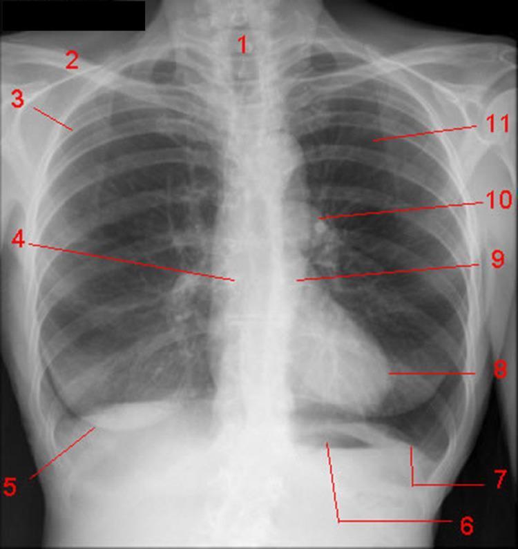
This diagnostic image is a posteroanterior (PA) chest X-ray of a healthy adult, serving as an anatomical diagram of the thorax. The radiograph displays key structures labeled for educational purposes: the trachea (1) appears as a vertical radiolucent (dark) air column in the midline; the clavicle (2) is a dense radiopaque bone at the superior margin; and the posterior portion of the fourth rib (3) is visible in the upper lung field. Lower down, the right main bronchus (4) branches from the carina. Soft tissue features include the lower margin of the right breast (5). The abdomen-thorax interface highlights the gastric air bubble (6) beneath the left diaphragmatic dome (7). The cardiac silhouette is represented by the left ventricle (8), while the descending aorta (9) and left pulmonary artery (10) are seen in the mediastinum and hilum. The left lung (11) exhibits normal radiolucency. This image demonstrates standard radiographic anatomy, spatial relationships of mediastinal structures, and common landmarks used in clinical imaging and diagnostic triage.
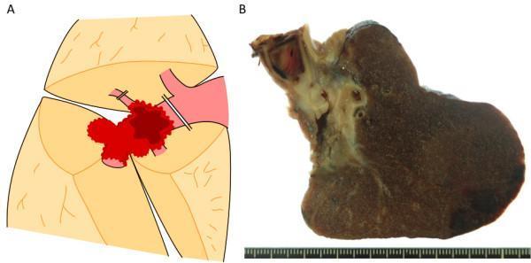
Educational panel illustrating surgical management and pathology of lung adenocarcinoma with vascular invasion. Panel A is a surgical diagram of the right lung hilum. It depicts a red-colored tumor invading the pulmonary trunk and the root of the posterior ascending branch. Surgical management is indicated by double lines representing the ligation and division of the posterior ascending branch and the clamping and suturing of the pulmonary trunk distal to the anterior trunk bifurcation. A brown area within the vessel represents an associated pulmonary artery thrombus. Panel B is a macroscopic clinical photograph of the resected lung specimen. It shows a 40 mm grayish-white tumor mass centered in the hilar region (S6). The specimen demonstrates direct continuous invasion into the pulmonary artery, resulting in complete occlusion of the pulmonary trunk by a massive, dense thrombus. This content illustrates advanced thoracic surgical techniques for vessel preservation (avoiding pneumonectomy) and the gross pathological appearance of T4 stage lung adenocarcinoma with intravascular extension.
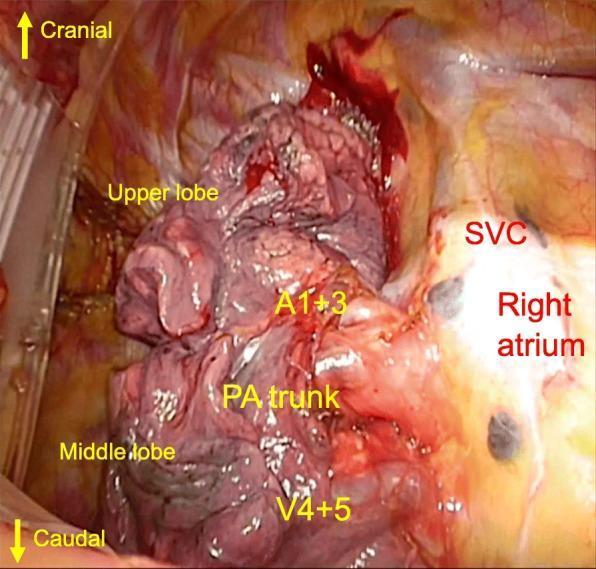
This clinical intraoperative photograph displays a forward surgical view of the right pulmonary hilum during a thoracic procedure, likely a right upper lobectomy. The image highlights the anatomical relationships between lung parenchyma and hilar vascular structures with directional markers indicating cranial and caudal orientations. The right upper lobe and middle lobe are visible, with the pulmonary artery (PA) trunk positioned between them. Notable vascular anatomy includes the superior vena cava (SVC) and right atrium, appearing as smooth, glistening, reddish-yellow structures lateral to the lung tissue. Specific segmental vessels are annotated: A1+3 is situated superior to the PA trunk, while V4+5 is located caudally. The image demonstrates a surgical scenario where the segmental veins V1 and V2+3 are not visible in their standard anterior hilar position, with the main pulmonary artery running anteriorly to them. This visual serves to illustrate anatomical variations relevant to safe hilar dissection and vascular control in thoracic surgery.
Root of the Lungs and Differences Between Both Lungs
Part 1 - The Root of the Lung
Definition
- Gray's Anatomy for Students, p. 204
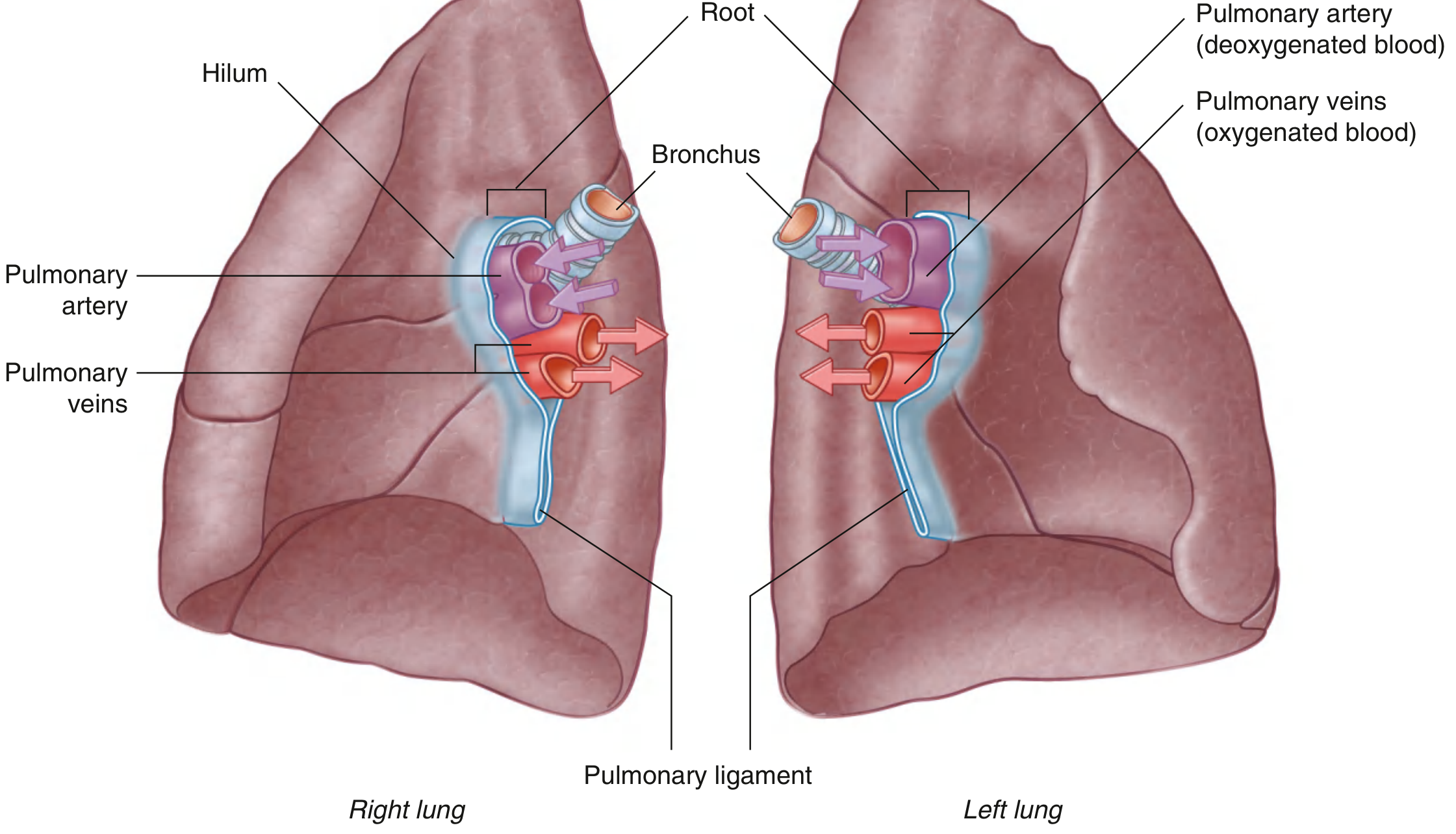
Contents of the Root (Within the Hilum)
| Structure | Detail |
|---|---|
| Pulmonary artery (1) | Carries deoxygenated blood to the lung |
| Pulmonary veins (2) | Carry oxygenated blood back to the left atrium |
| Main bronchus (1) | Carries air into the lung |
| Bronchial vessels | Nutrient supply to lung tissue |
| Nerves | Autonomic (sympathetic and parasympathetic) |
| Lymphatics | Lymphatic drainage of the lung |
- Pulmonary artery - superior position
- Pulmonary veins - inferior position
- Bronchus - somewhat posterior position
- Gray's Anatomy for Students, p. 204
Arrangement at the Root - Right vs Left (Key Difference)
| Side | Arrangement at Root |
|---|---|
| Right | The superior lobar (eparterial) bronchus branches from the main bronchus within the root (before entering the lung), and sits superior to the pulmonary artery |
| Left | The superior lobar bronchus branches within the lung itself (not in the root). The pulmonary artery is the most cranial structure at the left hilum. |
- Color Atlas of Human Anatomy Vol 2, p. 211
Pulmonary Ligament
- May stabilize the position of the inferior lobe
- Accommodates the translocation of structures in the root during breathing
Relations of the Root
Part 2 - Differences Between the Right and Left Lung
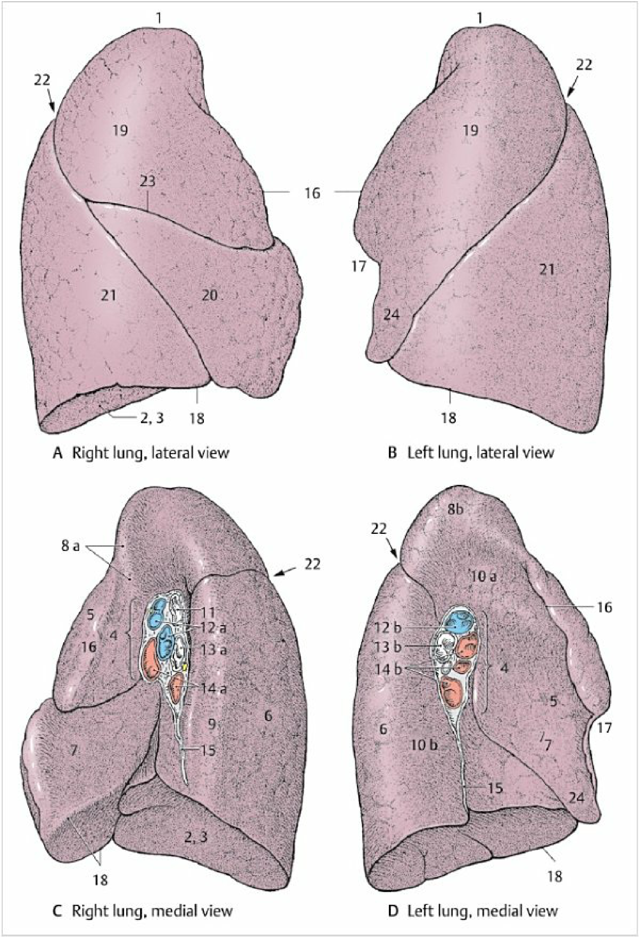
Comparison Table
| Feature | Right Lung | Left Lung |
|---|---|---|
| Size | Larger | Smaller (heart occupies left side) |
| Shape | Shorter and wider | Longer and narrower |
| Lobes | 3 lobes - Superior, Middle, Inferior | 2 lobes - Superior and Inferior |
| Fissures | 2 fissures - Oblique + Horizontal | 1 fissure - Oblique only |
| Oblique fissure | Starts at T4 spinous process, crosses 5th interspace laterally, follows rib 6 anteriorly | Starts between T3-T4, slightly more oblique |
| Horizontal fissure | Present - follows 4th intercostal space from sternum to oblique fissure at rib 5 | Absent |
| Cardiac notch | Absent | Present - inferior medial surface notched by the heart projecting into left pleural cavity |
| Lingula | Absent | Present - tongue-like projection from the anteroinferior part of the superior lobe, overlying the heart |
| Bronchopulmonary segments | 10 segments | 9 segments (S1 and S2 fused on left) |
| Main bronchus | Shorter, wider, more vertical | Longer, narrower, more horizontal |
| Eparterial bronchus | Present - superior lobar bronchus branches in the root, above the pulmonary artery | Absent - all lobar bronchi are hyparterial |
| Hilum - superior structure | Right superior lobar bronchus (eparterial) | Left pulmonary artery |
| Mediastinal relations | Heart, IVC, SVC, azygos vein, esophagus | Heart, aortic arch, thoracic aorta, esophagus |
| Subclavian artery | Right subclavian artery related to superior lobe | Left subclavian artery related to superior lobe |
| Diaphragm | Right dome is higher (due to liver below) | Left dome is lower |
| Impressions on medial surface | Azygos vein arch, SVC, esophagus, right subclavian artery | Aortic arch, thoracic aorta, left subclavian artery groove |
- Gray's Anatomy for Students, pp. 205-207
- Color Atlas of Human Anatomy Vol 2, pp. 211-213
Why the Right Main Bronchus is More Significant Clinically
- Aspiration of foreign bodies (fall more readily into right bronchus)
- Inadvertent right endobronchial intubation during endotracheal intubation
Summary of Key Mnemonics
- Right lung = 3 lobes, 2 fissures, 10 segments, eparterial bronchus
- Left lung = 2 lobes, 1 fissure, 9 segments, cardiac notch + lingula, NO eparterial bronchus
- Root contents = PA + 2PV + Bronchus + Bronchial vessels + Nerves + Lymphatics
- Relations: Vagus = posterior to root; Phrenic = anterior to root
Explain ligaments related to hip joint along with applied anatomy
hip joint ligaments iliofemoral pubofemoral ischiofemoral anatomy diagram
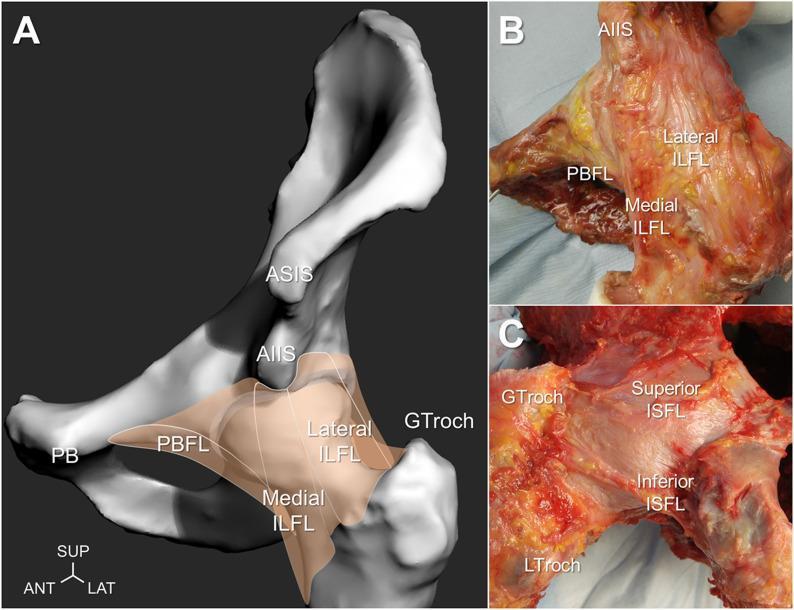
This composite educational image illustrates the anatomy of the human hip joint's capsular ligaments. Part A shows a 3D anatomical diagram of a left hip model in a neutral position, highlighting the iliofemoral ligament (ILFL) with its lateral and medial branches, and the pubofemoral ligament (PBFL). Part B is a clinical photograph of a cadaveric specimen from an anterior view in external rotation, demonstrating the distinct fibrous bands of the lateral and medial ILFL originating from the anterior inferior iliac spine (AIIS), alongside the medially located PBFL near the pubis. Part C is a posterior cadaveric view of the hip in internal rotation, showcasing the ischiofemoral ligament (ISFL). It reveals the differentiation between the Superior ISFL, which runs horizontally toward the greater trochanter (GTroch), and the Inferior ISFL, which has an oblique orientation toward the lesser trochanter (LTroch). The images emphasize the complex arrangement of these primary ligaments and their roles in providing mechanical stability and restricting rotational motion of the hip joint.
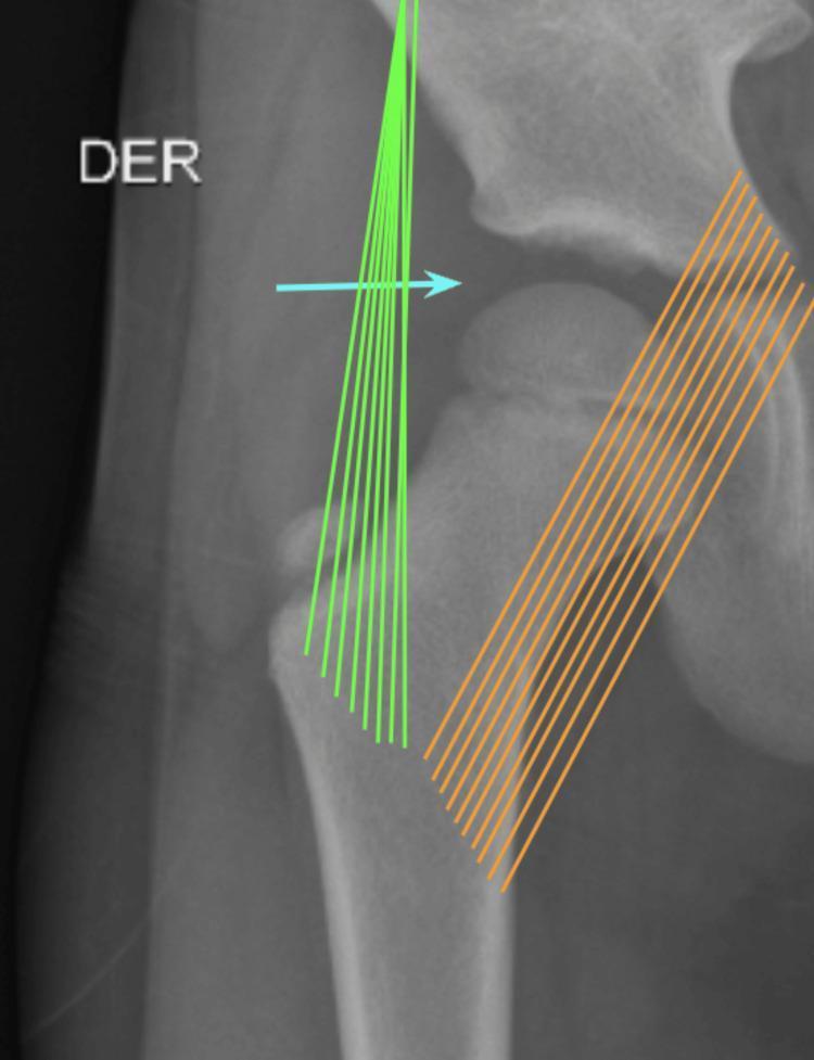
This diagnostic radiograph (X-ray) shows an anteroposterior (AP) view of a pediatric right hip joint, specifically focused on the coxofemoral articulation. The image features overlaid schematics illustrating the procedural approach for an anterolateral arthrocentesis. Key anatomical structures visible include the femoral head, femoral neck, greater trochanter, and the acetabulum of the pelvis. Colored annotations are used to demonstrate ligamentous anatomy and procedural navigation: fanned green lines represent the iliofemoral ligament located laterally, and parallel orange lines represent the pubofemoral ligament located medially. A horizontal blue arrow indicates the needle insertion trajectory and entry point into the joint space, which has been widened through articular traction in a dorsal recumbent position. This visual aid serves as a clinical guide for orthopedic residents and medical students to understand the anatomical landmarks and biomechanical considerations during therapeutic and diagnostic joint aspiration or injection procedures.
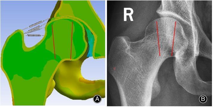
A side-by-side comparison illustrating finite element (FE) modeling and clinical imaging of the proximal femur. (A) A biomechanical model of a right hip joint showing von Mises stress transmission pathways. The proximal femur and acetabulum are color-coded (green and yellow) to represent mechanical stress distribution. Spring models connect the greater trochanter to the ilium, simulating the support provided by the hip ligaments (iliofemoral, pubofemoral, and ischiofemoral). Two vertical red lines indicate the orientation of principal stress pathways within the femoral head. (B) A matching anteroposterior (AP) X-ray of a human right proximal femur. The radiographic image shows the dense cortical bone and the intricate trabecular patterns (compressive and tensile trabeculae) within the femoral neck and head. Superimposed red lines correspond to the orientation of the primary pressure osteons and trabecular groups, validating the computational model's representation of bone architecture and stress-bearing regions. This comparison is used to study disease mechanisms like femoral head necrosis and the mechanical impact of surgical interventions.
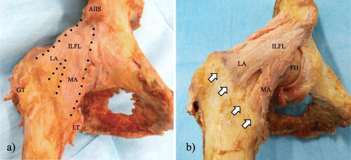
This clinical photograph displays two cadaveric dissections (labeled a and b) of the anterior aspect of a human hip joint, specifically highlighting the anatomy of the iliofemoral ligament (ILFL), also known as the Y-ligament of Bigelow. In panel (a), the ILFL is outlined by a black dotted line, demonstrating its proximal attachment near the anterior inferior iliac spine (AIIS). The ligament bifurcates into two distinct bundles: the lateral arm (LA), which extends toward the greater trochanter (GT), and the medial arm (MA), which descends toward the lesser trochanter (LT). Panel (b) shows the deep capsular anatomy after the removal of superficial fibers and the pubofemoral ligament. White arrows indicate the intertrochanteric line, identifying the distal footprints where the LA and MA insert into the femur. The femoral head (FH) is partially visible beneath the capsular structures. These images are utilized to teach the gross anatomy and surgical landmarks of the hip’s capsular reinforcement system, relevant for orthopedic surgery and physical therapy education.