
ORIF with Internal fixation and DHS for left intratronchatric left side
intertrochanteric femur fracture DHS dynamic hip screw ORIF fixation
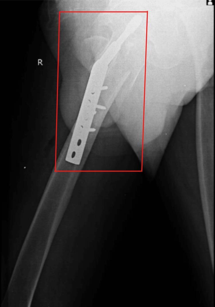
This lateral view X-ray radiography demonstrates the postoperative results of open reduction internal fixation (ORIF) for a right-sided proximal femur fracture. The image shows a dynamic hip screw (DHS) system in situ, consisting of a large-diameter lag screw traversing the femoral neck into the femoral head, coupled with a side plate secured to the femoral shaft using multiple cortical screws. The hardware is positioned to stabilize an intertrochanteric fracture with subtrochanteric extension. The lateral projection allows for assessment of the sagittal alignment of the femur and the central placement of the lag screw within the femoral head. There are visible radiolucent lines indicating the original fracture planes between the intertrochanteric fragments and the femoral shaft. This imaging is characteristic of orthopedic trauma management in adult patients following a low-energy fall, illustrating the mechanical stabilization of extracapsular hip fractures to facilitate early mobilization and rehabilitation.
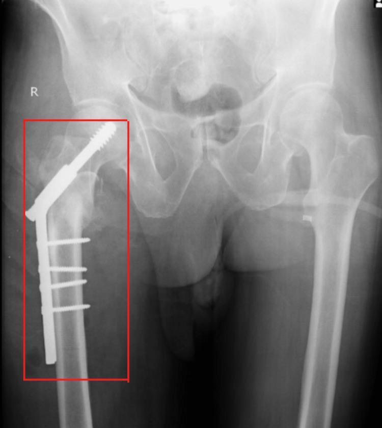
An anteroposterior (AP) X-ray of the pelvis and bilateral hips showing internal fixation of a right proximal femur fracture. The image captures the pelvic girdle, sacroiliac joints, and proximal femurs. On the right side, a Dynamic Hip Screw (DHS) system is visible, consisting of a large-diameter lag screw traversing the femoral neck into the femoral head, coupled with a lateral side plate. The plate is secured to the femoral shaft with four cortical screws. This hardware illustrates the post-operative management of an intertrochanteric hip fracture. The contralateral left hip appears anatomically normal without hardware. An 'R' marker denotes the right anatomical side. The imaging serves as a clinical example of Open Reduction Internal Fixation (ORIF) and is used to evaluate hardware positioning, fracture alignment, and subsequent healing.
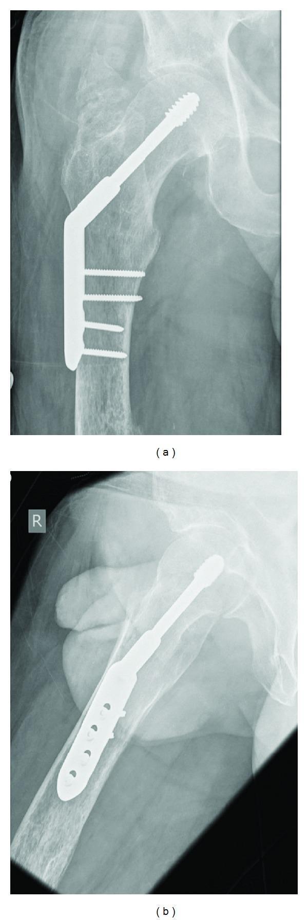
Two postoperative plain film radiographs (Anteroposterior and Lateral views) demonstrating surgical fixation of a right intertrochanteric hip fracture. The imaging displays a Dynamic Hip Screw (DHS) system consisting of a large-diameter lag screw inserted through an angled barrel into the femoral head, traversing the fracture site to provide compression. A lateral side plate is affixed to the proximal femoral shaft with four cortical screws. The AP view (a) shows the anatomical alignment of the proximal femur with the lag screw positioned centrally within the femoral head. The lateral view (b), marked with an 'R' indicator, confirms the hardware position and reveals the soft tissue contours of the thigh. Key landmarks visible include the acetabulum, greater trochanter, and the proximal femoral shaft. This visual material is used in orthopedic education to illustrate the internal fixation of extracapsular hip fractures and the components of the DHS construct.
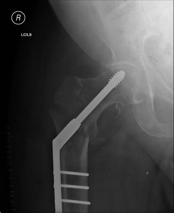
This diagnostic image is an anteroposterior (AP) plain radiograph of the right hip and proximal femur, demonstrating postoperative internal fixation of an intertrochanteric fracture. The primary orthopedic implant is a Dynamic Hip Screw (DHS) system. It features a large-diameter lag screw with a serrated distal tip centrally positioned within the femoral head to provide compression across the fracture site. This lag screw is coupled with a side plate that is securely fixed to the lateral cortex of the femoral shaft using three transverse cortical screws. The design of the DHS allows for controlled collapse and impaction along the axis of the lag screw during the weight-bearing and healing process. Radiographically, the femur exhibits features suggestive of osteopenia, characterized by reduced bone density and thinning of the cortical margins. The image captures the relationship between the femoral head, the greater and lesser trochanters, and the pelvic acetabulum, providing a clear demonstration of surgical management for geriatric hip trauma in an orthopedic clinical context.
ORIF with Dynamic Hip Screw (DHS) for Left Intertrochanteric Fracture
Overview
- Pfenninger and Fowler's Procedures for Primary Care, 3rd Ed, p. 1311
- Grainger & Allison's Diagnostic Radiology, p. 1162
Fracture Classification (AO/OTA)
| Type | Description |
|---|---|
| A1 | Simple 2-part fracture, stable, intact medial cortex |
| A2 | Comminuted/multifragmentary, medial wall disruption, unstable |
| A3 | Reverse oblique or transverse, highly unstable |
Implant Choice
- Screw-side plate device (DHS) - for stable A1 fractures and select A2
- Intramedullary nail (cephalomedullary nail) - preferred for A2 unstable and all A3 fractures
"The mainstay of treatment of intertrochanteric femoral fractures is fixation with a screw-side plate device or intramedullary device."
- Campbell's Operative Orthopaedics 15th Ed 2026, p. 3449
DHS Components
| Component | Function |
|---|---|
| Lag screw (sliding screw) | Large-diameter screw inserted into femoral head; allows controlled axial collapse/impaction |
| Barrel | Hollow cylinder within the side plate that allows the lag screw to slide |
| Side plate (2-4 hole) | Fixed to lateral femoral shaft cortex with cortical screws |
| Compression screw | Optional; applied through the end of the barrel to compress at fracture site |
Surgical Technique (Step-by-Step)
Patient Setup
- Supine on a radiolucent fracture table
- Traction applied through the foot/boot to reduce the fracture
- C-arm fluoroscopy confirms reduction in AP and lateral views
- For the left side: surgeon stands on the left lateral side
Reduction
- Closed reduction is attempted first under fluoroscopy
- If inadequate, limited open reduction or formal open approach (Watson-Jones) may be required
- Goal: anatomic or near-anatomic alignment
Exposure
- Begin the skin incision at the vastus ridge and extend distally along the lateral thigh
- Incise through the iliotibial band and split the fascia of the vastus lateralis longitudinally
- Elevate the vastus lateralis anteriorly off the lateral intermuscular septum, coagulating branches of the profunda femoris artery as encountered
- Sharply incise the origin of the vastus lateralis for retraction and plate placement
Stabilization
- Guide pin insertion: Insert a guide pin through the angled guide into the center-center position within the femoral head. Advance to ~5 mm from the articular surface and measure.
- Reaming: Set the triple reamer to 5 mm less than the measurement. Ream the femoral neck and head channel. Do NOT advance the guide pin into the pelvis while reaming.
- Lag screw selection: Choose a screw length equal to the triple reamer measurement (or 5 mm shorter if controlled collapse is desired). Minimum coverage: screw no shorter than 5 mm less than measured length.
- Lag screw insertion: Using the insertion wrench, insert the lag screw with the barrel plate to appropriate depth. ~180° rotation = 1.5 mm advancement. The wrench handle must be oriented to the femoral axis when complete.
- Side plate seating: Advance the side plate onto the lateral femoral cortex. Use a tamp to fully seat the plate onto the lag screw barrel. Remove guide pin and insertion wrench.
- Plate fixation: Secure the plate with a plate clamp or initial screw. Place 2-3 bicortical cortical screws through a 2-4 hole plate into the femoral shaft.
- Compression: Release traction, then insert a compression screw or apply manual compression. Obtain final fluoroscopic images (AP and lateral views).
Key Technical Principles
Tip-Apex Distance (TAD)
- The most important predictor of screw cut-out (implant failure)
- TAD = sum of distances from lag screw tip to apex of femoral head on AP + lateral views
- TAD < 25 mm is the target to minimize cut-out risk
Reduction Quality
- Avoid varus malalignment - increases the risk of cut-out
- Slight valgus or neutral neck-shaft angle is preferred
Anti-rotation Screw
- A supplementary derotation screw can be added for basicervical or rotationally unstable patterns
Postoperative Care
- Weight-bearing: Partial to full weight-bearing as tolerated is encouraged early (usually within 24-48 hours), depending on fracture stability and bone quality
- DVT prophylaxis: Anticoagulation started postoperatively
- Rehabilitation: Early mobilization with physiotherapy is key to outcomes
Complications
| Complication | Notes |
|---|---|
| Lag screw cut-out | Most common implant failure; related to high TAD, varus reduction, poor bone quality |
| Non-union / malunion | More common with unstable patterns |
| Wound infection | Perioperative antibiotics reduce risk |
| Implant failure | Risk with A3 fractures if DHS chosen instead of IM nail |
| AVN | Rare (extracapsular fracture), unlike femoral neck fractures |
| DVT/PE | Thromboembolic prophylaxis mandatory |
DHS vs. Intramedullary Nail
| Feature | DHS (Screw-Side Plate) | Cephalomedullary Nail |
|---|---|---|
| Best for | Stable A1, simple A2 | Unstable A2, A3, reverse oblique |
| Biomechanics | Extramedullary; longer moment arm | Intramedullary; shorter moment arm (better for unstable) |
| Blood loss | Slightly more (open lateral exposure) | Less (percutaneous) |
| Cost | Lower | Higher |
| Failure risk in A3 | High - not recommended | Preferred |
Radiographic Images