Supraglottic airway devices in detail
Reading File
Finding Sources
Finding Sources
Searching PubMed
"supraglottic airway devices"[MeSH Terms] AND "laryngeal masks"[MeSH Terms]
Reading File
Reading File
Reading File
Reading File
Reading File
Reading File
Reading File
Reading File
Reading File
Reading File
Reading File
Reading File
Reading File
Loading Image
Loading Image
Reading File
I now have very comprehensive information from multiple authoritative textbooks. Let me compile the full detailed response.
Supraglottic Airway Devices (SADs) - Comprehensive Overview
Definition and General Principles
Supraglottic airway devices (SADs) are a category of airway management tools that sit above the level of the glottis in the oropharynx/hypopharynx, providing a conduit for ventilation without requiring laryngoscopy or tracheal intubation. All SADs consist of a tube connected to a respiratory circuit attached to a hypopharyngeal component that seals and directs airflow toward the glottis, trachea, and lungs. They occlude the esophagus with varying effectiveness, reducing gastric distension - but none provide the aspiration protection of a properly placed, cuffed endotracheal tube (ETT).
SADs are used for:
- Spontaneously breathing and mechanically ventilated patients during anesthesia
- Rescue ventilation when bag-mask ventilation (BMV) and ETT intubation fail
- As conduits for tracheal intubation in the difficult airway
- Pre-hospital and resuscitation scenarios
Classification
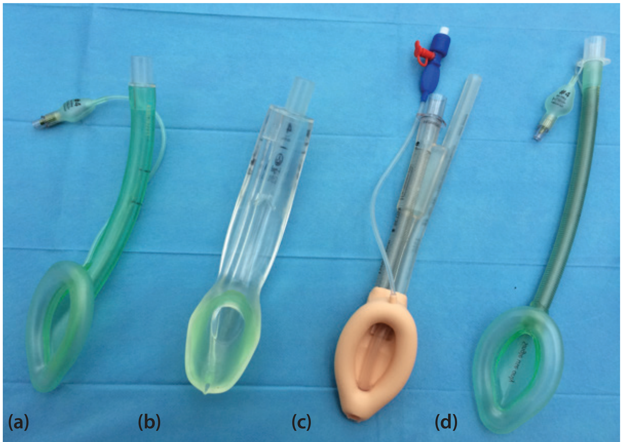
First-Generation SADs
Simple devices providing a perilaryngeal seal; no gastric drain.
- LMA Classic
- LMA Unique (disposable version)
- LMA Flexible
Second-Generation SADs
Incorporate a gastric drain/suction port in addition to the perilaryngeal seal, improving safety and efficacy with positive-pressure ventilation.
- LMA ProSeal
- LMA Supreme
- i-gel
- Air-Q
Esophageal/Pharyngeal Airway Devices (distinct SAD subtype)
Seal both the pharynx and esophagus; not perilaryngeal.
- Esophageal-Tracheal Combitube
- King Laryngeal Tube (King LT/LTS)
Specific Devices
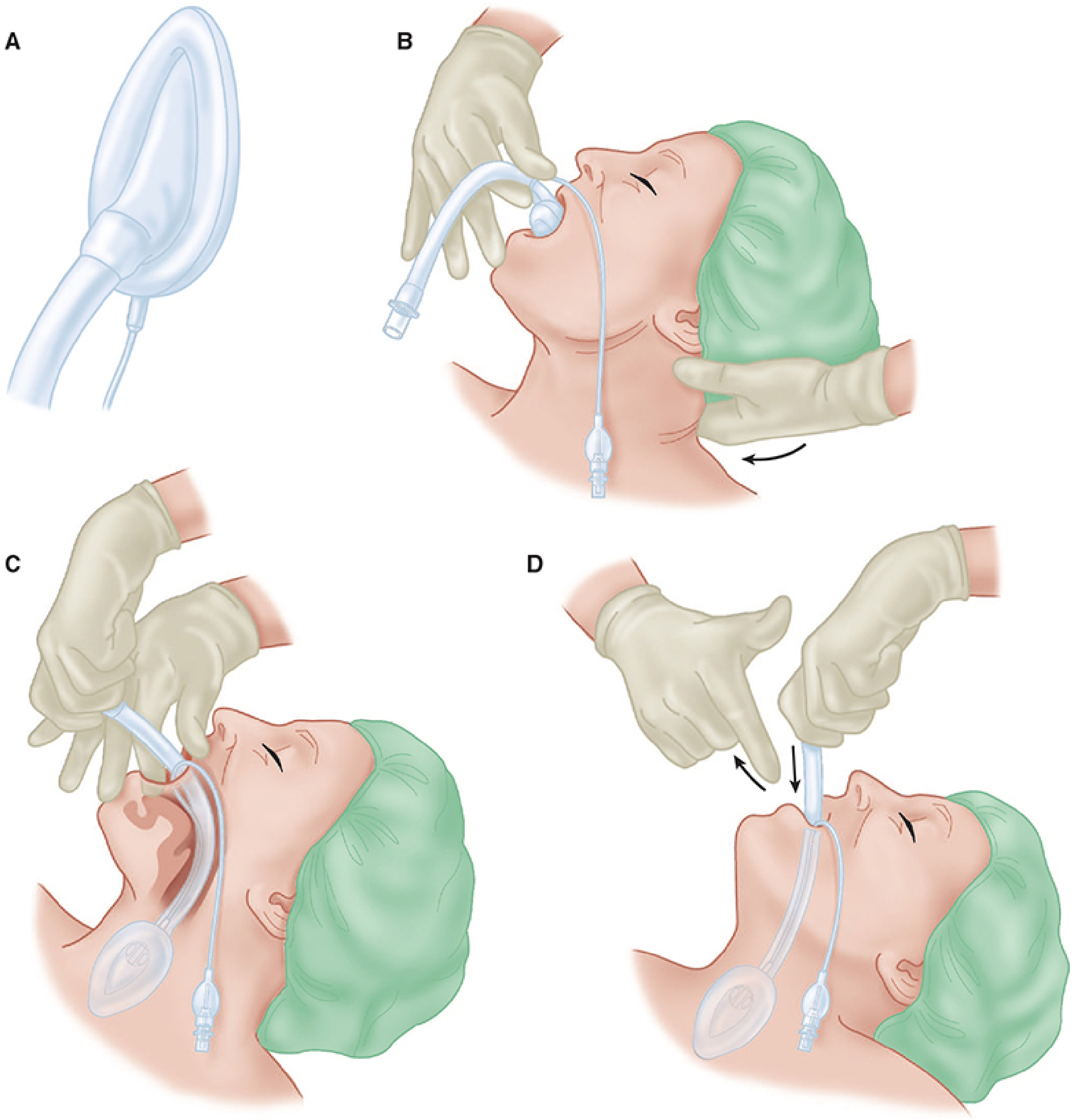
1. LMA Classic (cLMA)
The original and most widely studied SAD, invented by Dr. Archie Brain.
Structure: Wide-bore tube with a proximal 15-mm connector and a distal elliptical inflatable cuff. The deflated cuff is inserted blindly into the hypopharynx; once inflated, it forms a low-pressure seal around the laryngeal inlet. The ideally positioned cuff is bordered by:
- Base of tongue - superiorly
- Pyriform sinuses - laterally
- Upper esophageal sphincter - inferiorly
Sizes:
| Mask Size | Patient | Weight (kg) | Cuff Volume (mL) |
|---|---|---|---|
| 1 | Infant | <6.5 | 2-4 |
| 2 | Child | 6.5-20 | Up to 10 |
| 2.5 | Child | 20-30 | Up to 15 |
| 3 | Small adult | >30 | Up to 20 |
| 4 | Normal adult | <70 | Up to 30 |
| 5 | Larger adult | >70 | Up to 30 |
Insertion technique (Morgan & Mikhail):
- Choose appropriate size; check cuff for leaks
- Deflate cuff so the leading edge is wrinkle-free, facing away from the aperture
- Lubricate the back side of cuff only
- Ensure adequate anesthesia/muscle relaxation (slightly more than for an oral airway)
- Place patient in sniffing position (neck flexed, head extended)
- Hold device like a pen; index finger at junction of tube and cuff
- Press the tip against the hard palate and slide along the palate down into the hypopharynx until resistance is felt
- Inflate cuff; longitudinal black line should face cephalad (toward upper lip)
- Secure with tape
The LMA partially protects the larynx from pharyngeal secretions but not from gastric regurgitation. Remove only when the patient has regained airway reflexes (signaled by coughing and mouth opening on command).
Performance:
- Successful ventilation in ~98% of adults with known difficult airways
- ~90-95% success in unexpectedly difficult airways
- 88-100% placement success rate overall
2. LMA ProSeal (first second-generation SAD)
The ProSeal was the first SGA to incorporate a gastric drain port, fundamentally improving both positioning diagnosis and safety.
Key features (Barash Clinical Anesthesia):
| Feature | Clinical Impact |
|---|---|
| Gastric drain tube | Confirms device position (suprasternal notch test), allows active/passive gastric emptying, protection from aspiration |
| Posterior cuff | Increases airway seal pressure (≥40 cm H₂O, vs ~20 cm H₂O for cLMA) |
| Bite block | Prevents obstruction from biting; confirms positioning if ≥50% is within oral cavity |
- First insertion success slightly lower than cLMA
- Size down from cLMA equivalent
- Particularly advantageous for obese patients, intra-abdominal procedures
3. LMA Supreme (single-use ProSeal variant)
- Disposable, fixed-curvature device
- Supports inspiratory pressures >35 cm H₂O
- Gastric drain tube incorporated
- Rigid pre-curved shaft - does not require cuff inflation index-finger technique
- Available for adult and pediatric use
4. i-gel
Unique design: Solid elastomer gel body on a plastic barrel - no inflatable cuff. The gel conforms to perilaryngeal anatomy.
- A drain tube runs from the distal tip (positioned over the esophageal inlet) to an outlet lateral to the airway connector - accepts up to a 14-French gastric tube
- Airway leak pressures: 24-30 cm H₂O in adults
- Lower incidence of postoperative sore throat than LMA
- Less visible blood on device at removal
- Modestly shorter insertion times vs LMA ProSeal, but slightly lower oropharyngeal leak pressures
- The solid mask does not change shape with body temperature (contrary to popular belief)
5. Intubating LMA (ILMA) / LMA Fastrach
Invented by Dr. Archie Brain in 1997; designed as a conduit for tracheal intubation.
Structural differences from cLMA:
- Rigid stainless steel handle for precise positioning
- Rigid curved airway tube (allows one-hand insertion)
- Epiglottic elevating bar (EEB) that lifts the epiglottis as the tube advances
- Wide enough shaft for a standard ETT
- Specialized straight wire-reinforced ETT with soft molded tip designed for atraumatic blind passage
Insertion technique:
- Neutral head position (non-extended) - different from cLMA
- Use the handle to rotate the mask into the pharynx
- Stabilize ventilation after insertion
- Chandy maneuver: (i) rotate ILMA in sagittal plane until ventilation resistance is minimal; (ii) gently lift from posterior pharyngeal wall just before ETT passage
- The "up-down maneuver" corrects down-folded epiglottis: withdraw ILMA ~5-6 cm while cuff remains inflated, then slide back pressing against posterior pharynx
Advantages over cLMA in difficult airways:
- Technically easier to use than cLMA in emergency settings
- More practical when definitive airway (ETT) is the goal
- Better performance with head in neutral position / in-line stabilization of the cervical spine
- Particularly useful in: beards, severe facial trauma, obesity (none of these inhibit placement)
- Useful when brisk supraglottic bleeding makes conventional intubation difficult
The original reusable ILMA should be removed soon after ETT placement is confirmed (rigidity exerts high tissue pressure). A disposable single-use version is available.
6. LMA CTrach
A variant of the ILMA incorporating a fiberoptic camera and monitor to visualize ETT passage - essentially a video-assisted intubating LMA. Now largely superseded by video laryngoscopy.
7. LMA Flexible (Reinforced LMA)
- Wire-reinforced flexible shaft resists kinking and compression
- Shaft can be moved out of the surgical field without displacing the cuff
- Useful for oral/dental/ENT surgery where the airway tube must be flexible
- Not suitable as an intubation conduit
8. Esophageal-Tracheal Combitube
A double-lumen tube inserted blindly through the mouth.
Structure:
- Longer blue tube: occluded distal tip, gas exits through side perforations
- Shorter clear tube: open tip, no side perforations
- Two inflatable cuffs: 100-mL proximal pharyngeal cuff + 15-mL distal cuff
- Both cuffs inflated after device is advanced until the two black rings lie between the teeth
Function:
- In ~95% of insertions, the distal end sits in the esophagus - ventilate through the blue (longer) tube, gas exits side perforations into the larynx
- If the tube enters the trachea (5%), ventilate through the clear (shorter/tracheal) tube
- The clear tube can also drain gastric contents
- Requires minimum mouth opening; not appropriate for patients <4 feet tall
9. King Laryngeal Tube (King LT / King LTS-D)
A single-lumen tube with two low-pressure cuffs inflated via a single, common pilot valve.
Mechanism: When positioned correctly:
- Distal cuff ocstructs the upper esophagus
- Proximal cuff seals the oral and nasal pharynx
- Apertures between cuffs serve as ventilation orifices
Sizes: 0 to 5 (children to large adults). Requires minimum mouth opening of 2.3 cm.
King LTS-D (suction version): Single-use; adds a lumen terminating distal to the esophageal cuff for gastric drainage. Successfully used as emergency airway in a pregnant patient during failed RSI.
Limitations: Less effective than LMA in children under 10 years. Not recommended for children <10 kg. Higher posterior hypopharyngeal mucosal pressures than LMA ProSeal - possible impairment of pharyngeal perfusion. Rare reports of acute tongue and uvula ulceration.
Troubleshooting: If ventilation is difficult after King LT insertion with cuffs inflated, the tube is likely inserted too deeply - slowly withdraw until compliance improves.
10. Air-Q (Cookgas Perilaryngeal Airway)
- Functions as both an elective SGA and intubation conduit (blind or fiberoptic-assisted)
- Cuff grossly similar in shape to LMA Classic cuff
- Airway seal pressures: 25-30 cm H₂O
- Sizes 0.5 to 4.5
- Insertion technique similar to LMA
- Fill cuff with <10 mL air (poor seal often due to over-inflation)
- If airway obstruction occurs after insertion: up-down motion of barrel realigns epiglottis
- Self-pressurizing air-Q variant: no cuff insufflation required; intracuff pressure varies with airway pressure - may improve fiberoptic visualization
Comparison of Key SADs
| Device | Generation | Gastric Drain | Seal Pressure | Intubation Conduit | Key Feature |
|---|---|---|---|---|---|
| LMA Classic | 1st | No | ~20 cm H₂O | Poor (microlaryngeal tube only) | Gold standard reference |
| LMA Unique | 1st | No | ~20 cm H₂O | No | Disposable cLMA |
| LMA Flexible | 1st | No | ~20 cm H₂O | No | Wire-reinforced, surgical field |
| LMA ProSeal | 2nd | Yes | ≥40 cm H₂O | No | First with gastric drain |
| LMA Supreme | 2nd | Yes | >35 cm H₂O | No | Disposable ProSeal |
| i-gel | 2nd | Yes | 24-30 cm H₂O | Yes (some sizes) | No inflatable cuff, gel seal |
| ILMA / Fastrach | Intubating | No | ~20 cm H₂O | Yes (primary function) | Epiglottic elevating bar |
| King LT | Esophageal | No (LT) | Pharyngeal seal | No | Single pilot valve |
| King LTS-D | Esophageal | Yes | Pharyngeal seal | No | Gastric drain lumen |
| Combitube | Esophageal | Yes | Dual cuff | No | Dual-lumen, esophageal/tracheal |
| Air-Q | 2nd | Partial | 25-30 cm H₂O | Yes | Self-pressurizing variant available |
Indications
- Elective anesthesia: Suitable for low-risk surgeries not requiring ETT (peripheral, ophthalmic, brief ENT procedures)
- Difficult airway rescue: When BMV and ETT intubation have both failed - "cannot intubate, cannot oxygenate" scenario
- Conduit for intubation: ILMA, air-Q, or cLMA with fiberoptic scope
- Prehospital/cardiac arrest: Where endotracheal intubation is not feasible or causes unacceptable pauses in CPR
- Pediatric airways: LMA Classic allows adequate ventilation in >98% of adults and is reliable in difficult pediatric airways
- Cervical spine immobilization: ILMA performs better than cLMA with head in neutral/in-line stabilization
Contraindications
Absolute:
- Limited mouth opening (<1.5-2 cm)
- Pharyngeal pathology (abscess, obstruction)
- Glottic or subglottic obstruction
Relative:
- Full stomach / high aspiration risk (pregnancy, hiatal hernia, intestinal obstruction, delayed gastric emptying)
- High airway resistance or low pulmonary compliance (peak inspiratory pressures >30 cm H₂O) - second-generation devices with higher seal pressures are preferred if SAD is necessary
- Inadequate sedation/paralysis
Note: SADs may be used as an airway salvage technique even in patients with aspiration risk, when the alternative is hypoxia.
Advantages Over ETT
From Barash Clinical Anesthesia (Table 28-9), advantages of SADs in supraglottic surgery include:
- Improved protection from blood and surgical debris
- Reduced cardiovascular responses (no tracheal stimulation)
- Reduced coughing on emergence
- Reduced intraoperative bronchospasm
- Reduced laryngospasm after removal
- Improved oxygen saturation after removal
- Ability to administer O₂ until full return of airway reflexes
- Postoperative sore throat: 4-50% (vs 30-60% with ETT)
Complications
- Aspiration of gastric contents (primary risk - reduced but not eliminated by 2nd-gen devices)
- Laryngospasm, bronchospasm, coughing, gagging
- Nerve injuries (rare): Hypoglossal, lingual, and/or recurrent laryngeal nerves - typically manifest within 48 hours, resolve in 1 hour to 18 months. Cause: pressure neuropraxia from tube/cuff. Risk factors include small masks, lidocaine lubrication, nitrous oxide, cuff over-inflation, difficult insertion, non-supine positioning, cervical joint disease
- Postoperative sore throat and dysphagia: No single device consistently lower; all better than ETT
- Partial or complete airway obstruction (usually due to epiglottic down-folding)
- Gastric distension if esophagus lies within the rim of the cuff
- Tongue and uvular ulceration (reported with King LT)
Removal
An SGA should be removed either:
- When the patient is deeply anesthetized (avoids stimulation in excitation stage), or
- After airway reflexes have fully returned - patient opens mouth on command
Many clinicians remove the LMA with the cuff fully inflated so it acts as a "scoop" for secretions above the mask, carrying them out of the airway.
SAD as Intubation Conduit
When both BMV and intubation have failed, SADs can bridge to a definitive airway:
- ILMA/Fastrach: Highest success for blind intubation; Chandy maneuver optimizes position; FIS-guided intubation through ILMA achieves higher first-attempt success than blind technique
- cLMA + FIS: Possible but requires a microlaryngeal tube due to narrow shaft
- cLMA + Aintree catheter + FIS: The Aintree intubation catheter (hollow airway exchange catheter) fits over a standard FIS; allows exchange from cLMA to ETT
- Most newer SGAs: Shaft wide enough for standard-sized ETT with or without FIS guidance
- LMA CTrach: Built-in camera facilitates guided intubation (largely replaced by video laryngoscopy)
Special Populations
Pediatrics:
- LMA Classic is the most extensively tested in children; more reliable than bag-mask in 98% of cases
- Provides safer means of ventilation than BMV in neonates and infants prone to gastric distension
- King LT: not recommended for children <10 kg; less effective than LMA in children <10 years
- SADs are life-saving rescue devices in difficult pediatric airways
Obstetrics:
- SADs are not the primary airway of choice (aspiration risk)
- Acceptable as rescue device when intubation fails
- King LTS-D has been used successfully during failed RSI for cesarean section
Cervical spine injury:
- ILMA preferred over cLMA; performs better with head in neutral/in-line stabilization
- Less cervical spine movement than direct laryngoscopy
Obese patients:
- ILMA: beard, severe facial trauma, and obesity do not inhibit placement
- LMA ProSeal/Supreme: higher seal pressures accommodate higher ventilation pressures often needed
Sources:
- Morgan and Mikhail's Clinical Anesthesiology, 7e, pp. 581-587
- Miller's Anesthesia, 10e, pp. 5950-5951
- Barash, Cullen & Stoelting's Clinical Anesthesia, 9e, pp. 2322-2327
- Roberts and Hedges' Clinical Procedures in Emergency Medicine, pp. 99-100
- Scott-Brown's Otorhinolaryngology Head & Neck Surgery, Vol. 1, p. 384
- Tintinalli's Emergency Medicine, p. 219
Mapleson breathing systems in detail
Finding Sources
Finding Sources
Reading File
Reading File
Reading File
Reading File
Reading File
Reading File
Loading Image
Loading Image
Reading File
I have outstanding content and the two key diagrams. I now have everything needed for a thorough, well-illustrated answer. Let me compile the complete response.
Mapleson Breathing Systems - Comprehensive Overview
Historical Background
In 1954, William Mapleson described the elimination of carbon dioxide in five different semiclosed breathing systems, which became classically designated A through E. Subsequently, Willis et al. added a sixth system - the F circuit. Together, these form the Mapleson classification of breathing systems. - Barash, Cullen & Stoelting's Clinical Anesthesia, 9e
General Principles
What They Are
Mapleson systems are semi-open (non-rebreathing or partial-rebreathing) anesthetic breathing circuits that share several features with the circle system:
- Accept fresh gas flow (FGF) from an anesthesia machine
- Supply gas from a reservoir to meet inspiratory flow and volume requirements
- Eliminate CO₂
How They Differ From the Circle System
- Bidirectional gas flow (no unidirectional valves)
- No CO₂ absorber - CO₂ elimination depends entirely on washout by fresh gas inflow
- Therefore require higher FGF rates to prevent rebreathing
- No risk of volatile anesthetic degradation by CO₂ absorbent
- Simpler, lighter, fewer components
Key Concept: CO₂ Rebreathing
CO₂ rebreathing is determined by multiple factors:
- Fresh gas inflow rate
- Patient's minute ventilation
- Mode of ventilation (spontaneous vs. controlled)
- Tidal volume and respiratory rate
- I:E ratio and duration of the expiratory pause
- Peak inspiratory flow rate
- Volume of reservoir tube and breathing bag
- Whether ventilation is via mask or ETT
- CO₂ sampling site
Performance is best understood by studying the expiratory phase of the respiratory cycle.
Components of Mapleson Circuits
1. Breathing Tubes (Corrugated Reservoir Tubing)
- Large diameter (22 mm) - creates a low-resistance pathway and acts as a gas reservoir
- Volume should be ≥ patient's tidal volume in most circuits to minimize FGF requirements
- Compliance of the breathing tube largely determines circuit compliance; high compliance = significant tidal volume lost to circuit expansion
- Example: circuit with compliance of 8 mL/cm H₂O pressurized to 20 cm H₂O loses 160 mL per breath to circuit expansion
- Not present in Mapleson C
2. Fresh Gas Inlet (FGI)
- Continuous inflow of anesthetic gases mixed with O₂/air from the anesthesia machine
- The relative position of the FGI is the key distinguishing feature among Mapleson circuits and is the primary determinant of efficiency
3. Adjustable Pressure-Limiting (APL) Valve (Pop-Off Valve, Pressure-Relief Valve)
- Controls pressure by allowing excess gas to vent to atmosphere or scavenging system
- During spontaneous ventilation: APL should be fully open (circuit pressure remains negligible)
- During assisted/controlled ventilation: partially closed to allow positive pressure build-up
- Position relative to FGI is the other key differentiating feature among circuits
4. Reservoir Bag
- Provides a gas reservoir to meet peak inspiratory flow demands
- Allows hand ventilation and monitoring of ventilation during spontaneous breathing
- Not present in Mapleson E
The Six Mapleson Systems
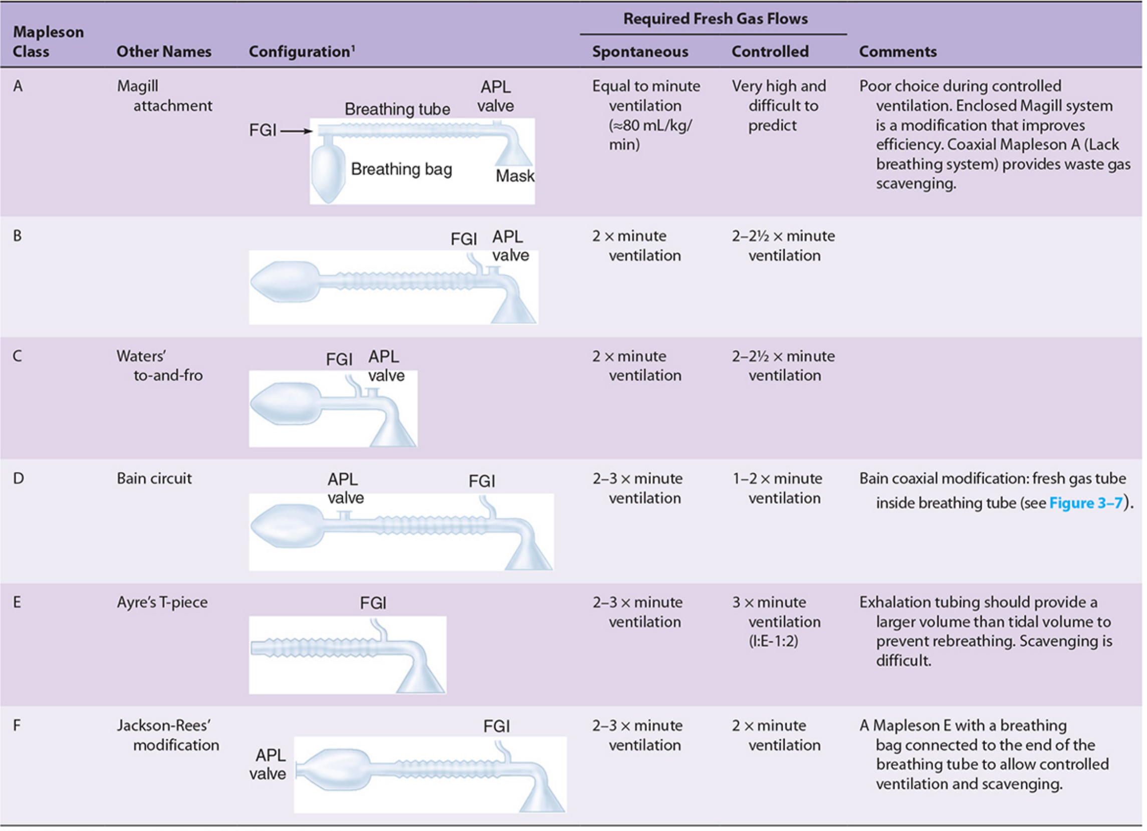
Mapleson A - "Magill Circuit" / "Magill Attachment"
Configuration:
- FGI enters near the reservoir bag (far from the patient)
- APL valve is positioned near the patient (at the mask end)
- Reservoir bag is at the machine end
Performance - Spontaneous Ventilation:
Best of all circuits. Required FGF = equal to the patient's minute ventilation (~80 mL/kg/min).
Mechanism: During expiration, alveolar gas (CO₂-laden) fills the breathing tube toward the FGI end. Dead space gas (CO₂-free) fills the tube closest to the patient. Before the next inspiration, fresh gas flowing in from the reservoir end pushes alveolar gas out through the APL valve near the patient. Since dead space gas is closest to the patient, the next inspiration is free of CO₂.
Performance - Controlled Ventilation:
Worst of all circuits. Requires very high FGF (>3 times minute ventilation, practically 20 L/min) - unpredictable and difficult.
Mechanism: During positive-pressure controlled ventilation, the APL valve is partially closed. Exhaled alveolar gas stagnates during the expiratory phase rather than being vented, accumulating in the breathing tube near the patient. Rebreathing of CO₂ becomes substantial.
Summary: Excellent for spontaneous ventilation; poor choice for controlled ventilation.
Modifications:
- Enclosed Magill system: improves efficiency
- Coaxial Mapleson A (Lack breathing system): incorporates fresh gas tube inside the breathing tube; facilitates waste gas scavenging because the APL valve is displaced away from the patient
Mapleson B
Configuration:
- FGI and APL valve are both located near the patient (at the mask end)
- Reservoir bag at the opposite end
Performance:
- Spontaneous ventilation: FGF = 2× minute ventilation
- Controlled ventilation: FGF = 2-2.5× minute ventilation
The proximity of FGI and APL valve means both fresh and alveolar gas mix near the patient and are vented together, making this moderately inefficient for both modes. The B and C systems behave similarly because their functional arrangements are closely related.
Current use: Rarely used today.
Mapleson C - "Waters' To-and-Fro" Circuit
Configuration:
- FGI and APL valve both near the patient (similar to B)
- No corrugated reservoir tubing (shortest of all Mapleson circuits)
- Reservoir bag is directly connected near the patient
Performance:
- Spontaneous ventilation: FGF = 2× minute ventilation
- Controlled ventilation: FGF = 2-2.5× minute ventilation
Functionally similar to Mapleson B. The absence of corrugated tubing makes it compact, but this reduces the gas reservoir.
Current use: Rarely used today; occasionally used for patient transport or resuscitation.
Mapleson D
Configuration:
- FGI enters near the patient (at the mask end)
- APL valve is near the reservoir bag (away from the patient)
- Reservoir bag at the machine end
- This is the exact inverse of the Mapleson A
Performance:
- Spontaneous ventilation: FGF = 2-3× minute ventilation
- Controlled ventilation: FGF = 1-2× minute ventilation (most efficient for controlled ventilation)
Mechanism during controlled ventilation: Fresh gas enters near the patient and "pushes" exhaled alveolar gas away from the patient toward the APL valve, which vents it. This results in effective CO₂ washout with moderate FGF.
Key insight (Morgan & Mikhail): "Interchanging the position of the APL valve and the fresh gas inlet transforms a Mapleson A into a Mapleson D circuit. Simply moving components completely alters the fresh gas requirements."
Most important modification: The Bain Circuit (see below)
Current use: The D/E/F group is the most widely used today. The Bain circuit is the most popular iteration in the United States.
Mapleson E - "Ayre's T-Piece"
Configuration:
- FGI enters near the patient
- Open expiratory limb (reservoir tube) at the distal end - no APL valve, no reservoir bag
- The only Mapleson system without a breathing bag
- T-piece design: the patient connection, FGI, and expiratory limb form a T
Performance:
- Spontaneous ventilation: FGF = 2-3× minute ventilation
- Controlled ventilation: FGF = 3× minute ventilation (I:E ratio 1:2 assumed; exhalation tubing must provide a volume larger than tidal volume to prevent rebreathing)
Advantages:
- Minimal dead space
- Very low resistance (no valves at all)
- Particularly suitable for pediatric patients
Limitations:
- Cannot support spontaneous ventilation without modification unless FGF is very high
- Controlled ventilation requires intermittent occlusion of the expiratory limb
- Scavenging is very difficult (open expiratory limb)
- No ability to monitor or assist ventilation (no bag)
Current use: ICU patients being liberated from mechanical ventilation; resource-constrained environments for inhaled anesthetic delivery to spontaneously breathing patients.
Mapleson F - "Jackson-Rees Circuit" (Jackson-Rees Modification of Ayre's T-Piece)
Configuration:
- A Mapleson E (Ayre's T-piece) with a breathing bag added to the expiratory limb
- The bag has an open "tail" which may have an adjustable valve
- FGI enters near the patient
- APL valve is on the open tail of the bag (away from the patient)
Performance:
- Spontaneous ventilation: FGF = 2.5-3× minute ventilation
- Controlled ventilation: FGF = 1.5-2× minute ventilation
Advantages over Mapleson E:
- The bag allows monitoring of spontaneous ventilation
- Allows manual controlled ventilation (squeeze the bag, partially occlude the tail)
- Allows CPAP application
- Still has low resistance and minimal dead space
Pediatric use: The Jackson-Rees is commonly used in pediatrics due to low resistance, minimal dead space, and ease of ventilation assessment. Compared to a pediatric circle system: less breathing difficulty (though this difference is largely negligible), less gastric insufflation.
Current use: Widely used for patient transport and in the ICU, particularly in the United States, because it resembles the breathing bag on a standard anesthesia machine.
Summary: FGF Requirements
| System | Other Name | APL Valve Position | FGI Position | Spontaneous FGF | Controlled FGF | Efficiency Ranking |
|---|---|---|---|---|---|---|
| A | Magill | Near patient | Near bag | = MV (~80 mL/kg/min) | Very high (>3× MV) | Best for spontaneous |
| B | - | Near patient | Near patient | 2× MV | 2-2.5× MV | Moderate |
| C | Waters' to-and-fro | Near patient | Near patient | 2× MV | 2-2.5× MV | Moderate |
| D | Bain circuit | Near bag | Near patient | 2-3× MV | 1-2× MV | Best for controlled |
| E | Ayre's T-piece | None | Near patient | 2-3× MV | 3× MV (I:E 1:2) | Only supports spontaneous |
| F | Jackson-Rees | On bag tail | Near patient | 2.5-3× MV | 1.5-2× MV | Good for both modes |
Memory aid for efficiency:
- A = Best for spontaneous (FGF = 1× MV)
- D/E/F = Best for controlled (FGF ~1.5-2.5× MV)
- B/C = Intermediate (FGF ~2-2.5× MV for both)
Functional Groupings (Barash)
Three distinct functional groups exist:
- Group A (alone) - unique behavior, best for spontaneous ventilation
- Group B and C - similar behavior, intermediate efficiency for both modes
- Group D, E, and F - the "T-piece group," best for controlled ventilation, most widely used today
Special Modification: The Bain Circuit
The Bain circuit is a coaxial modification of the Mapleson D, introduced by Bain and Spoerel (1972).
Design:
- Fresh gas flows through a narrow inner tube inside the outer corrugated hose
- The inner tube enters the corrugated hose near the reservoir bag but empties into the circuit at the patient end
- Exhaled gases pass down the outer corrugated hose, around the central tubing, and are vented through the pop-off valve near the reservoir bag
Advantages over conventional Mapleson D:
- Lightweight and convenient - decreases circuit bulk
- Better heat and humidity retention - exhaled warm gas in the outer tube warms the inspired fresh gas via countercurrent heat exchange
- Easier scavenging - APL valve is away from the patient
- Disposable versions available
Required FGF: 2.5× minute ventilation to prevent rebreathing (same as Mapleson D).
Hazards:
- Kinking or disconnection of the inner fresh gas tube - most serious hazard; if unrecognized, causes significant rebreathing of exhaled CO₂ and potential hypercapnia
- The outer corrugated tube must be transparent for ongoing inspection of the inner tube
Pethick test for inner tube integrity (Barash):
- High-flow O₂ is fed into the circuit while occluding the patient end until the reservoir bag fills
- Patient end is opened and O₂ is flushed into the circuit
- If inner tube is intact: Venturi effect at the patient end decreases circuit pressure → reservoir bag deflates
- If inner tube is leaking/disconnected: Fresh gas escapes into the expiratory limb → reservoir bag remains inflated
This test is recommended as part of the preanesthesia check when using a Bain circuit.
Advantages of Mapleson Systems (General)
- Low resistance to gas flow - no unidirectional valves
- Simple, few components - lightweight, easy to maintain
- Rapid changes in inspired gas composition - no large circuit volume to equilibrate
- No CO₂ absorber - no risk of volatile anesthetic degradation (e.g., compound A production with sevoflurane)
- Small dead space - especially Mapleson E and F (important in pediatrics)
- Useful for patient transport and ICU - portable, requires no electricity
Disadvantages
- High FGF requirements (except Mapleson A for spontaneous ventilation) - less economical with carrier gas and volatile agent compared to circle system
- Less heat and humidity conservation - FGF continuously removes moisture and heat (partial exception: Bain circuit)
- Difficult waste gas scavenging - especially Mapleson A, E (APL valve near patient or absent)
- Not suitable as primary anesthetic delivery in modern practice in high-resource settings (circle system preferred)
- Some rebreathing always occurs unless FGF is very high
- Mapleson A is a poor choice for controlled ventilation
Clinical Uses Today
| Setting | Preferred Circuit | Reason |
|---|---|---|
| Patient transport | Jackson-Rees (F), Mapleson C | Portable, familiar, allows manual ventilation |
| ICU liberation from ventilator | Mapleson E (Ayre's T-piece) | Simple T-piece weaning |
| Pediatric anesthesia | Jackson-Rees (F) | Low resistance, minimal dead space, easy ventilation monitoring |
| Resource-constrained environments | Mapleson A, D, E | Simple, inexpensive, no electricity required |
| Head and neck/ENT surgery | Mapleson A (Lack modification) | Low-bulk circuit away from surgical field |
Sources
- Morgan and Mikhail's Clinical Anesthesiology, 7e, pp. 83-88
- Miller's Anesthesia, 10e, pp. 2351-2354
- Barash, Cullen & Stoelting's Clinical Anesthesia, 9e, pp. 2010-2013
This is a shared conversation. Sign in to Orris to start your own chat.