
MRI Spine Analysis - Narsaben Mavi, 40F
Film 1 - Whole Spine Screening Sagittal (T2-weighted)
- Alignment: Cervical lordosis, thoracic kyphosis, and lumbar lordosis are all preserved. No spondylolisthesis detected.
- Vertebral bodies: Heights are maintained throughout. No compression fractures, no osteolytic/osteoblastic lesions. Bone marrow signal is uniform.
- Disc disease: Cervical and thoracic disc hydration is relatively well preserved. Lower lumbar discs (especially L4-L5 and L5-S1) show mild T2 signal loss (darkening), consistent with early/mild degenerative disc disease.
- Spinal cord: Normal caliber and uniform signal from cervicomedullary junction to conus medullaris (which terminates at the normal L1-L2 level). No abnormal intramedullary T2 signal (no syrinx, no myelomalacia).
- Thecal sac/CSF space: Patent throughout - no high-grade central stenosis.
Films 2 & 3 - Cervical Spine Axial T2-weighted Views
- Upper cervical levels: Discs are well-contained with minimal posterior bulging; anterior CSF space preserved.
- Mid-to-lower cervical levels (C4-C7): Mild-to-moderate diffuse disc bulging. Mild bilateral uncovertebral joint hypertrophy (arthrosis), mildly narrowing neural foramina bilaterally - but no high-grade foraminal stenosis or acute disc extrusion.
- Central canal: Adequate bony canal diameter throughout. Anterior CSF ring mildly effaced at mid-cervical levels due to disc bulging, but no severe central canal stenosis.
- Cord signal: No focal abnormal T2 hyperintensity within the spinal cord - no compressive myelopathy.
- Vertebral arteries: Patent, symmetric flow voids in bilateral transverse foramina.
- Paraspinal muscles: Normal bulk and signal bilaterally.
Films 4 & 5 - Cervical Spine Sagittal + Coronal Views
- Mild straightening of cervical lordosis (likely postural/muscle spasm-related).
- Mild marginal osteophytes at anterior and posterior margins at C4-C5, C5-C6, and C6-C7 - mild spondylosis.
- C5-C6 and C6-C7: Mild disc desiccation (loss of bright T2 signal), mild height loss, and small posterior disc-osteophyte complexes causing mild effacement of the anterior subarachnoid space.
- No significant cord compression. Cord signal remains normal and homogeneous throughout.
- Straight cervical spine, no scoliosis.
- Cervical nerve roots appear symmetric bilaterally without gross mass lesions or foraminal stenosis.
- Normal craniocervical junction; no Chiari malformation.
- Paraspinal soft tissues symmetric, no masses or fluid collections.
Summary of Findings
| Region | Finding | Severity |
|---|---|---|
| Cervical (C5-C6, C6-C7) | Disc desiccation + osteophytes (spondylosis) | Mild |
| Cervical (mid-lower) | Posterior disc-osteophyte bulges + uncovertebral hypertrophy | Mild |
| Cervical canal | Mild anterior CSF effacement, no high-grade stenosis | Mild |
| Cervical cord | Normal - no myelopathy, no syrinx | Normal |
| Lumbar (L4-L5, L5-S1) | Early disc degeneration (T2 signal loss) | Mild |
| Vertebral bodies (all levels) | No fractures, no lesions | Normal |
Clinical Impression
Disclaimer: This is a visual AI assessment of printed MRI films photographed at an angle. It is not a substitute for a formal radiologist's report from DICOM digital images. All findings must be correlated clinically and confirmed by a qualified radiologist.The formal radiology reports have now arrived. These reveal significantly more serious findings than what was visible on the films alone - particularly the basilar invagination with compressive myelopathy, which is a major finding. Let me read the reports carefully and provide a full explanation.
Official Radiology Report - Full Explanation
The Findings Explained in Plain Language
1. Trans-pedicular Fixation Screws at C2 - PREVIOUS SURGERY
2. Basilar Invagination with Compressive Myelopathy - THE MOST SERIOUS FINDING
- The tip of the dens is ~7 mm above Chamberlain's line (the standard radiological line from the back of the hard palate to the back rim of the foramen magnum - anything above this is abnormal)
- This is causing narrowing of the effective foramen magnum diameter
- Resulting in compression of the cervico-medullary junction (the critical junction between the lower brainstem/medulla and the upper spinal cord)
- There is intramedullary hyperintensity on T2 MRI inside the spinal cord itself - this bright signal means the cord tissue is being damaged/has edema from compression
3. Partial Atlanto-Occipital Assimilation
4. C2 and C3 Partial Block Vertebrae with Fusion of Posterior Elements
5. Disc-Osteophyte Complexes at C3-C4, C4-C5, C5-C6, and C6-C7
6. MR Myelography - Extradural Impressions at Multiple Levels
7. From the Dorso-Lumbar Screening Film
| Finding | What it Means |
|---|---|
| Sacralization of L5 | The L5 vertebra is partially or fully fused to the sacrum - a congenital variant, usually benign |
| L3-L4 and L4-L5 diffuse disc bulges | Mild lumbar disc disease causing anterior thecal sac indentation, no nerve root compression |
| Dorsal (thoracic) spine unremarkable | Thoracic spine is normal |
AP Spinal Canal Diameters (Cervical)
| Level | Diameter | Comment |
|---|---|---|
| C2-3 | 12.2 mm | Mildly narrow (normal >13 mm) |
| C3-4 | 12.5 mm | Mildly narrow |
| C4-5 | 11.1 mm | Significantly narrow (stenotic) |
| C5-6 | 11.1 mm | Significantly narrow |
| C6-7 | 11.8 mm | Borderline narrow |
Summary - Priority of Findings
| Priority | Finding | Action Needed |
|---|---|---|
| 🔴 URGENT | Basilar invagination + cord signal change (compressive myelopathy) | Urgent neurosurgery referral |
| 🔴 HIGH | Prior C2 fixation screws - suggests prior attempt at stabilization | Surgical team review of previous procedure |
| 🟡 IMPORTANT | Atlanto-occipital assimilation + C2-C3 block vertebrae | Part of same congenital complex |
| 🟡 MODERATE | Multilevel cervical disc-osteophyte complexes (C3-C7) | Conservative management / monitor |
| 🟢 INCIDENTAL | L3-L5 disc bulges, L5 sacralization | Conservative management |
What Should Happen Next
-
Urgent neurosurgical consultation - the intramedullary T2 signal change (cord injury signal) at the cervico-medullary junction is not something that can be managed conservatively. Surgery typically involves posterior occipitocervical decompression and fusion, or in some cases transoral decompression, depending on reducibility.
-
Review of prior surgical history - the C2 pedicle screws indicate a previous operation. The neurosurgeon needs those records.
-
Neurological examination - to assess current deficits (upper/lower motor neuron signs, sensory levels, reflexes, gait, bladder function).
-
CT cervical spine - to better characterize the bony anatomy (craniocervical junction) for surgical planning.
Important: This is a complex congenital and degenerative condition. The combination of basilar invagination + atlanto-occipital assimilation + block vertebrae represents a congenital craniovertebral junction anomaly complex. The prior surgery suggests this has been known and treated before. The current MRI showing intramedullary signal change means the situation has progressed.
Disclaimer: This explanation is for informational purposes only and is not a substitute for evaluation by a qualified neurosurgeon or spine specialist. Please ensure this patient is seen urgently by a specialist.
Cervical Spine X-Ray Analysis
Views Taken
- Left film: Cervical AP (Anteroposterior - front to back view)
- Right film: Cervical Lateral (side profile view)
Key Finding: Post-Operative Cervical Spine with Posterior Fixation Hardware
What the Hardware Is
- Posterior cervical/occipitocervical fusion construct at the upper cervical spine
- The construct consists of bilateral metallic rods secured with bone screws
- The upper end of the construct anchors into the occipital bone (base of skull) via an occipital plate or occipital screws
- The screws extend down through C1, C2, and possibly C3 (pedicle/pars screws or lateral mass screws)
- This is a classic occipito-cervical fusion construct
- Craniovertebral junction instability (e.g., atlantoaxial instability, basilar invagination)
- Congenital anomalies of C1-C2 (atlanto-occipital assimilation, odontoid anomalies)
- Post-traumatic instability
- Rheumatoid or inflammatory conditions affecting the craniocervical junction (rare at this age)
AP View Findings
- Posterior rods and screws are visible projecting symmetrically over the upper cervical/occipital region - confirming bilateral placement
- Cervical spinous processes are aligned in the midline - no scoliosis
- Trachea is midline and patent
- Ribs and clavicles appear intact
- No obvious complications on this view
Assessment of Hardware Integrity
| Feature | Finding |
|---|---|
| Screw position | Appears well-placed and symmetrical bilaterally |
| Rod alignment | Intact, no obvious rod breakage |
| Craniocervical alignment | Maintained and fixed by the construct |
| Lower cervical spine (C3-C7) | Normal vertebral heights and disc spaces |
| Prevertebral soft tissue | Within normal limits - no swelling or haematoma |
Overall Impression
Note: This is a radiographic assessment only. Clinical correlation, assessment of neurological status, and formal surgical follow-up are essential. These X-rays would typically be part of a routine post-operative follow-up to confirm hardware position and fusion progress.

Operated case of rt ftp decompressive craniectomy..gcs e4vtm3
Post-Op CT Brain Analysis
GCS Interpretation
| Component | Score | Meaning |
|---|---|---|
| Eyes (E) | 4 | Opens eyes spontaneously |
| Verbal (V) | T | Tracheostomy in situ - verbal not testable |
| Motor (M) | 3 | Abnormal flexion (decorticate posturing) |
CT Brain Findings
1. Surgical Defect
- Large right frontotemporoparietal craniectomy defect - bone flap surgically removed
- Transcalvarial brain herniation - right cerebral hemisphere herniating outward through the surgical defect (this is expected and intentional - the purpose of decompressive craniectomy is to allow the brain to expand outward rather than downward)
- Right subgaleal fluid collection beneath the scalp flap - likely a seroma or liquefying hematoma (common post-op finding)
- Small pockets of pneumocephalus (intracranial air) - normal in the immediate post-operative period
2. Mass Effect and Midline Shift
- Leftward midline shift: approximately 8-10 mm - significant
- Right lateral ventricle - severely compressed and near-effaced from surrounding oedema and mass effect
- Left lateral ventricle - dilated (contralateral trapping/hydrocephalus), with signs of transependymal CSF flow around frontal and occipital horns
- Third ventricle - displaced to the left
- Basal cisterns - partially compressed/compromised - this is a warning sign of impending descending transtentorial herniation
3. Parenchymal Findings
| Finding | Location | Significance |
|---|---|---|
| Diffuse hypoattenuation / oedema | Right frontal, temporal, parietal lobes | Severe cytotoxic + vasogenic oedema |
| Loss of grey-white differentiation | Right hemisphere | Indicates ischaemic/oedematous injury |
| Parenchymal cavity / defect | Right temporal-deep parietal | Site of prior contusion evacuation or surgical tract |
| Residual hyperdense foci | Margins of the cavity | Residual blood / haemosiderin |
| Sulcal effacement | Diffuse right hemisphere | Consistent with severe cerebral swelling |
4. Contralateral Left Hemisphere
- Grey-white differentiation relatively preserved
- Mild left sulcal effacement secondary to the severe rightward mass effect pushing structures across midline
- No new contralateral extra-axial collection (no new subdural or epidural haematoma on the left)
Summary / Impression
- Severe right hemisphere cerebral oedema with transcalvarial herniation through craniectomy defect
- Significant leftward midline shift (~8-10 mm) - the craniectomy has partially decompressed the brain outward, but mass effect persists
- Right parenchymal cavity with marginal residual haemorrhage - post-evacuation site
- Partially compromised basal cisterns - warning of risk of descending transtentorial herniation
- Contralateral left hydrocephalus (trapped left ventricle) - may need monitoring for raised ICP on left side
- Right subgaleal collection - expected post-op finding
Clinical Correlation with GCS
- The M3 (decorticate posturing) reflects the severe right hemispheric damage and ongoing mass effect compressing corticospinal pathways
- Eyes opening spontaneously (E4) suggests intact reticular activating system at this time
- The partially compressed basal cisterns combined with midline shift of 8-10 mm explain the depressed consciousness
- The craniectomy has provided some decompression, but the persistent shift and cistern effacement indicate the patient remains at high risk
Key Concerns Requiring Monitoring
Disclaimer: This is an AI visual assessment of photographed CT films. All clinical decisions must be made by the treating neurosurgery team based on direct clinical examination, full DICOM CT review, and ICP monitoring data.
What I'd balck part at left side
What Are the Black Areas on CT Brain?
1. The Large Black Area on the RIGHT Side (Patient's Right = Left on Film)
- The craniectomy defect - the area where the bone has been surgically removed
- The brain is herniating outward through this gap, and the overlying soft tissue (scalp flap/subgaleal space) appears dark
- No bone rim is visible here - confirming the craniectomy
All Black Appearances Explained
| Black Structure | What It Is | Normal or Abnormal? |
|---|---|---|
| Large black region right side of film (patient's right) | Craniectomy defect - absent bone flap | Post-surgical - expected |
| Black spaces inside brain (ventricles) | CSF-filled ventricles (lateral, third, fourth) | Normal - CSF is black |
| Black sulci/grooves on brain surface | CSF in sulci between gyri | Normal |
| Diffuse black haziness in right hemisphere | Cerebral oedema / infarction - hypoattenuation | ABNORMAL - damaged brain tissue |
| Small black dots scattered | Pneumocephalus - air pockets post-surgery | Expected in early post-op period |
| Black around the orbits (eye sockets) | Normal air in paranasal sinuses / orbital fat | Normal |
Why Oedematous/Infarcted Brain Looks Black
- Oedema (swelling with water accumulation)
- Ischaemia/infarction (lack of blood supply)
Pt left side
The Black Area on the Patient's Left Side
Massive Left-Sided Subdural Hygroma
What it is:
How it got there - the mechanism:
"Contralateral subdural hygroma following decompressive craniectomy"
How large is it?
What is it doing to the brain?
| Effect | Finding |
|---|---|
| Left lateral ventricle | Severely compressed and near-effaced |
| Midline shift | Pushed rightward (toward the craniectomy side) |
| Left hemisphere | Severely compressed underneath the collection |
| Right lateral ventricle | Dilated (secondary obstructive hydrocephalus) |
Is this dangerous?
- Worsen consciousness level (consistent with GCS M3)
- Cause bilateral herniation risk
- Trap the right lateral ventricle (explaining the right ventriculomegaly)
- Compress the left hemisphere into ischaemia
Management options:
- Burr hole drainage of the left subdural hygroma
- Subdural drain placement
- Some cases resolve spontaneously if small - this one is too large for watchful waiting
- Must also address underlying right-side oedema
Burr hole craniotomy..procedure steps
Burr Hole Drainage - Step-by-Step Procedure
Pre-operative Preparation
- Consent - explain risks: rebleeding, infection, neurological deterioration, recurrence (~10-20%), seizures
- Position - supine, head turned away from operative side (left side up for this patient), head ring support
- Mark the site - based on CT: maximum collection thickness, usually frontal burr hole (Kocher's point area) ± parietal burr hole posteriorly for dependent drainage
- Anaesthesia - GA preferred; can be done under LA + sedation in high-risk patients
- Prep and drape - full sterile field, shave and prep the scalp
Operative Steps
Step 1 - Scalp Incision
- Small linear incision (~3-4 cm) down to the periosteum
- In the frontal region: ~2 cm anterior to the coronal suture, 2-3 cm lateral to midline
- Deepen to bone with monopolar cautery
- Apply self-retaining retractors
Step 2 - Periosteal Elevation
- Elevate periosteum off the skull with a periosteal elevator
- Expose a small area of bare bone (~2 cm diameter)
- Apply bone wax to any bleeding diploic vessels
Step 3 - Burr Hole Creation
- Apply a Hudson brace with perforator or high-speed cranial drill
- Drill the burr hole perpendicular to bone surface
- Switch to burr once inner cortex is thinned to enlarge to ~1.5-2 cm
- Copious irrigation during drilling to prevent thermal injury
- Wax any bony bleeding points
Step 4 - Dural Opening
- Identify the dura - it will be under tension if collection is large (may bulge)
- Coagulate the dura with bipolar cautery
- Open dura with No. 11 blade - small cruciate or X-shaped incision
- Control dural bleeding with bipolar
- Important: In chronic SDH/hygroma - old motor oil-coloured fluid will immediately drain; in hygroma - clear/xanthochromic CSF-like fluid drains
Step 5 - Drainage and Irrigation
- Allow passive drainage first - do NOT suction the brain
- Irrigate gently with warm normal saline via a soft rubber catheter
- Irrigate until fluid runs clear
- For two-burr-hole technique: place irrigation catheter in anterior burr hole, drain from posterior burr hole (gravity-assisted)
Step 6 - Drain Placement (Optional but recommended)
- Place a soft subdural drain (Jackson-Pratt or closed subdural drain) through the burr hole
- Aim anteriorly and inferiorly for dependent drainage
- Secure drain to scalp with suture
- Drain kept in situ for 24-48 hours post-op
- Connect to closed drainage bag at head level (not dependent - avoid over-drainage)
Step 7 - Closure
- Close dura loosely around drain (do not suture tight)
- Close galea with interrupted 2-0 Vicryl
- Close skin with staples or 3-0 Nylon
- Apply sterile dressing
Post-operative Management
| Parameter | Action |
|---|---|
| Position | Keep patient flat for 24-48 hrs (promotes brain re-expansion into the subdural space) |
| Hydration | IV fluids, ensure euvolemia - helps brain re-expansion |
| Drain | Monitor output; remove at 24-48 hrs |
| CT brain | Repeat CT at 24-48 hrs post-op to check re-expansion |
| Anticonvulsants | Continue / start prophylaxis |
| Antibiotics | Single dose peri-operative (Cefazolin) |
| ICP monitoring | Maintain if already in situ |
Special Considerations for This Patient
- The hygroma likely formed due to the pressure differential after right craniectomy
- Bilateral burr holes (frontal + parietal) on the left are preferable for large collections
- Brain re-expansion may be slow given the underlying right hemisphere injury
- Recurrence risk is higher in post-craniectomy hygromas - may need repeat drainage
- Consider cranioplasty of the right side eventually, which itself often reduces contralateral hygroma recurrence by restoring normal pressure dynamics
- Schwartz's Principles of Surgery, 11th Ed: Chronic SDH - "Most authorities agree that burr hole drainage with closed-system drainage is the first-line surgical treatment... recurrence rates approach 10-20%"
Complications to Watch For
Can you illustration by images
Medical surgical illustration showing burr hole craniotomy procedure steps for subdural hygroma drainage. Step 1: Patient positioned supine with head turned, surgical site marked on left frontoparietal scalp. Step 2: Linear scalp incision with retractors exposing skull bone. Step 3: Hudson brace drill creating burr hole through skull bone. Step 4: Dura exposed and opened with scalpel, dark fluid draining. Step 5: Irrigation catheter washing out subdural space with saline. Step 6: Closed subdural drain placed through burr hole, wound closed with sutures. Clean anatomical medical illustration style with labels, cross-section views showing skull layers (scalp, bone, dura, subdural space, brain).
Medical anatomical cross-section illustration showing layers of the skull and brain relevant to burr hole surgery. Detailed cutaway view showing: scalp (skin, subcutaneous tissue, galea, periosteum), skull bone (outer cortex, diploë, inner cortex), epidural space, dura mater, subdural space with fluid collection (hygroma shown as dark fluid layer), arachnoid membrane, subarachnoid space with CSF, pia mater, and brain cortex. Labels pointing to each layer. Clean medical textbook style illustration.
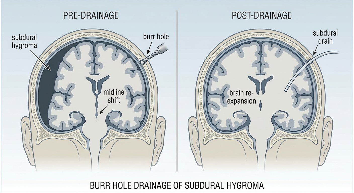
Medical illustration showing burr hole drainage of subdural hygroma, coronal cross-section of brain. Left side shows large black crescent-shaped subdural hygroma compressing the brain with midline shift to right. Arrow showing burr hole drill entering through skull. Right side shows post-drainage result with brain re-expanding, subdural drain in place, hygroma resolved. Labels: subdural hygroma, compressed brain, midline shift, burr hole, subdural drain, brain re-expansion. Clean anatomical medical textbook style.
Illustration 1 - Anatomy: Skull Layers (Understanding What You Are Drilling Through)
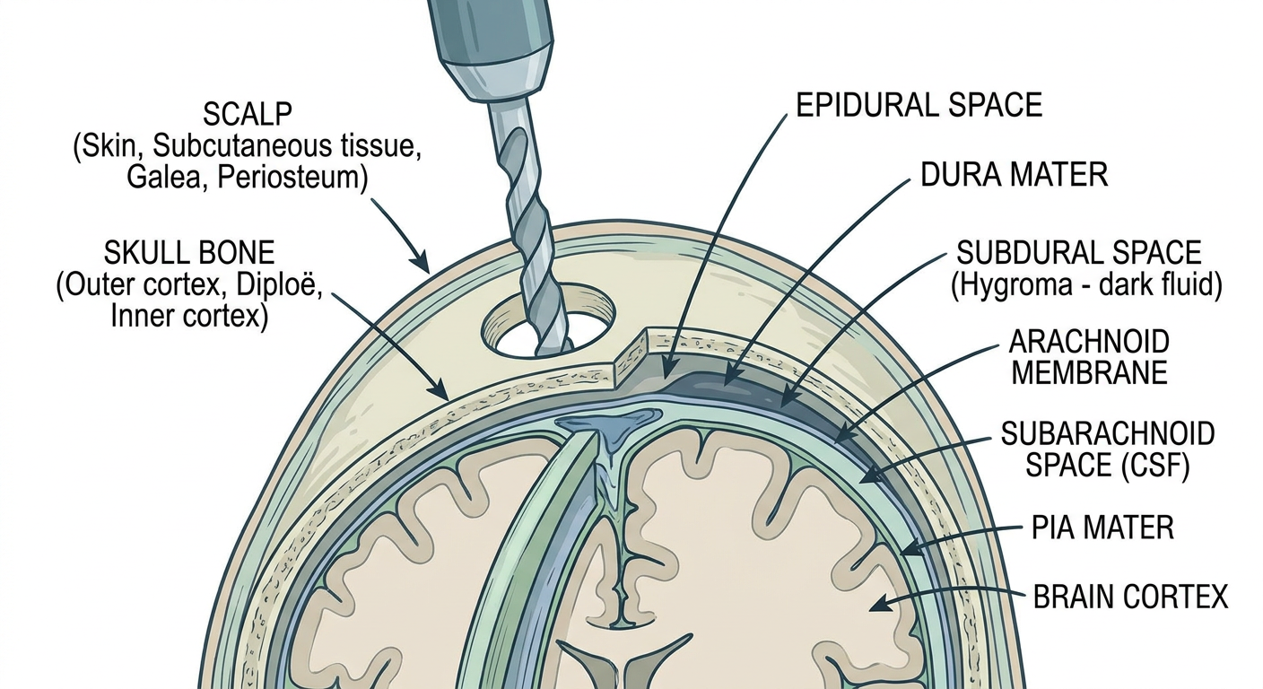
Illustration 2 - Step-by-Step Burr Hole Procedure
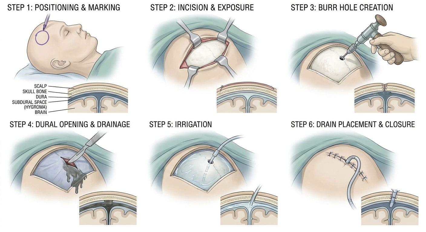
| Step | What Happens |
|---|---|
| 1 | Patient positioned, site marked, linear scalp incision |
| 2 | Retractors placed, bone exposed |
| 3 | Hudson brace/drill creates burr hole through bone |
| 4 | Dura coagulated and opened - fluid drains immediately |
| 5 | Warm saline irrigation until fluid runs clear |
| 6 | Subdural drain placed, wound closed in layers |
Illustration 3 - Before and After: Hygroma Drainage
Key Teaching Points from the Illustrations
- The subdural space is just inside the dura - you must drill through bone AND open the dura to reach it
- The drill goes perpendicular to the skull surface
- Once the dura is opened, the hygroma fluid drains by gravity and pressure - no active suction on the brain
- The drain is left pointing anteriorly into the subdural space and exits through the burr hole
- Brain re-expansion happens over 24-48 hours as fluid drains and the brain "fills" the space